EP0442308B1 - Matériau pour lignes de communication - Google Patents
Matériau pour lignes de communication Download PDFInfo
- Publication number
- EP0442308B1 EP0442308B1 EP91100995A EP91100995A EP0442308B1 EP 0442308 B1 EP0442308 B1 EP 0442308B1 EP 91100995 A EP91100995 A EP 91100995A EP 91100995 A EP91100995 A EP 91100995A EP 0442308 B1 EP0442308 B1 EP 0442308B1
- Authority
- EP
- European Patent Office
- Prior art keywords
- resin
- hollow spheres
- energy
- coating
- substrate
- Prior art date
- Legal status (The legal status is an assumption and is not a legal conclusion. Google has not performed a legal analysis and makes no representation as to the accuracy of the status listed.)
- Expired - Lifetime
Links
- 239000000463 material Substances 0.000 title claims description 49
- 238000004891 communication Methods 0.000 title description 28
- 229920005989 resin Polymers 0.000 claims description 51
- 239000011347 resin Substances 0.000 claims description 51
- 239000011248 coating agent Substances 0.000 claims description 27
- 238000000576 coating method Methods 0.000 claims description 27
- 238000000034 method Methods 0.000 claims description 24
- 239000013307 optical fiber Substances 0.000 claims description 17
- 230000008569 process Effects 0.000 claims description 14
- 239000000203 mixture Substances 0.000 claims description 11
- 238000010438 heat treatment Methods 0.000 claims description 6
- 238000001125 extrusion Methods 0.000 claims description 3
- 239000012530 fluid Substances 0.000 claims description 3
- 229920001169 thermoplastic Polymers 0.000 claims description 2
- 239000000758 substrate Substances 0.000 claims 13
- 229920000098 polyolefin Polymers 0.000 claims 1
- 239000010410 layer Substances 0.000 description 20
- -1 polypropylene Polymers 0.000 description 20
- 239000006260 foam Substances 0.000 description 17
- 239000011247 coating layer Substances 0.000 description 16
- 239000004698 Polyethylene Substances 0.000 description 15
- 229920000573 polyethylene Polymers 0.000 description 15
- 238000010586 diagram Methods 0.000 description 9
- 238000001816 cooling Methods 0.000 description 6
- 239000011148 porous material Substances 0.000 description 6
- 239000004743 Polypropylene Substances 0.000 description 5
- 229920001155 polypropylene Polymers 0.000 description 5
- 239000011342 resin composition Substances 0.000 description 5
- NIXOWILDQLNWCW-UHFFFAOYSA-M Acrylate Chemical compound [O-]C(=O)C=C NIXOWILDQLNWCW-UHFFFAOYSA-M 0.000 description 4
- NNPPMTNAJDCUHE-UHFFFAOYSA-N isobutane Chemical compound CC(C)C NNPPMTNAJDCUHE-UHFFFAOYSA-N 0.000 description 4
- 229920001577 copolymer Polymers 0.000 description 3
- 238000009826 distribution Methods 0.000 description 3
- 239000000835 fiber Substances 0.000 description 3
- 239000007789 gas Substances 0.000 description 3
- 238000003780 insertion Methods 0.000 description 3
- 230000037431 insertion Effects 0.000 description 3
- OEPOKWHJYJXUGD-UHFFFAOYSA-N 2-(3-phenylmethoxyphenyl)-1,3-thiazole-4-carbaldehyde Chemical compound O=CC1=CSC(C=2C=C(OCC=3C=CC=CC=3)C=CC=2)=N1 OEPOKWHJYJXUGD-UHFFFAOYSA-N 0.000 description 2
- XKRFYHLGVUSROY-UHFFFAOYSA-N Argon Chemical compound [Ar] XKRFYHLGVUSROY-UHFFFAOYSA-N 0.000 description 2
- IJGRMHOSHXDMSA-UHFFFAOYSA-N Atomic nitrogen Chemical compound N#N IJGRMHOSHXDMSA-UHFFFAOYSA-N 0.000 description 2
- KAKZBPTYRLMSJV-UHFFFAOYSA-N Butadiene Chemical compound C=CC=C KAKZBPTYRLMSJV-UHFFFAOYSA-N 0.000 description 2
- VYPSYNLAJGMNEJ-UHFFFAOYSA-N Silicium dioxide Chemical compound O=[Si]=O VYPSYNLAJGMNEJ-UHFFFAOYSA-N 0.000 description 2
- MCMNRKCIXSYSNV-UHFFFAOYSA-N Zirconium dioxide Chemical compound O=[Zr]=O MCMNRKCIXSYSNV-UHFFFAOYSA-N 0.000 description 2
- 230000003247 decreasing effect Effects 0.000 description 2
- 239000003822 epoxy resin Substances 0.000 description 2
- UHESRSKEBRADOO-UHFFFAOYSA-N ethyl carbamate;prop-2-enoic acid Chemical compound OC(=O)C=C.CCOC(N)=O UHESRSKEBRADOO-UHFFFAOYSA-N 0.000 description 2
- 238000005187 foaming Methods 0.000 description 2
- 230000005484 gravity Effects 0.000 description 2
- 239000001282 iso-butane Substances 0.000 description 2
- 239000007788 liquid Substances 0.000 description 2
- 238000004519 manufacturing process Methods 0.000 description 2
- 239000004005 microsphere Substances 0.000 description 2
- 239000002245 particle Substances 0.000 description 2
- 229920000647 polyepoxide Polymers 0.000 description 2
- 229920001296 polysiloxane Polymers 0.000 description 2
- 230000009467 reduction Effects 0.000 description 2
- 229920005992 thermoplastic resin Polymers 0.000 description 2
- 229920001187 thermosetting polymer Polymers 0.000 description 2
- HBGPNLPABVUVKZ-POTXQNELSA-N (1r,3as,4s,5ar,5br,7r,7ar,11ar,11br,13as,13br)-4,7-dihydroxy-3a,5a,5b,8,8,11a-hexamethyl-1-prop-1-en-2-yl-2,3,4,5,6,7,7a,10,11,11b,12,13,13a,13b-tetradecahydro-1h-cyclopenta[a]chrysen-9-one Chemical compound C([C@@]12C)CC(=O)C(C)(C)[C@@H]1[C@H](O)C[C@]([C@]1(C)C[C@@H]3O)(C)[C@@H]2CC[C@H]1[C@@H]1[C@]3(C)CC[C@H]1C(=C)C HBGPNLPABVUVKZ-POTXQNELSA-N 0.000 description 1
- PFRGGOIBYLYVKM-UHFFFAOYSA-N 15alpha-hydroxylup-20(29)-en-3-one Natural products CC(=C)C1CCC2(C)CC(O)C3(C)C(CCC4C5(C)CCC(=O)C(C)(C)C5CCC34C)C12 PFRGGOIBYLYVKM-UHFFFAOYSA-N 0.000 description 1
- 239000004925 Acrylic resin Substances 0.000 description 1
- NLHHRLWOUZZQLW-UHFFFAOYSA-N Acrylonitrile Chemical compound C=CC#N NLHHRLWOUZZQLW-UHFFFAOYSA-N 0.000 description 1
- OKTJSMMVPCPJKN-UHFFFAOYSA-N Carbon Chemical compound [C] OKTJSMMVPCPJKN-UHFFFAOYSA-N 0.000 description 1
- 239000004677 Nylon Substances 0.000 description 1
- 239000004264 Petrolatum Substances 0.000 description 1
- SOKRNBGSNZXYIO-UHFFFAOYSA-N Resinone Natural products CC(=C)C1CCC2(C)C(O)CC3(C)C(CCC4C5(C)CCC(=O)C(C)(C)C5CCC34C)C12 SOKRNBGSNZXYIO-UHFFFAOYSA-N 0.000 description 1
- 239000006087 Silane Coupling Agent Substances 0.000 description 1
- 229920001807 Urea-formaldehyde Polymers 0.000 description 1
- 238000010521 absorption reaction Methods 0.000 description 1
- PNEYBMLMFCGWSK-UHFFFAOYSA-N aluminium oxide Inorganic materials [O-2].[O-2].[O-2].[Al+3].[Al+3] PNEYBMLMFCGWSK-UHFFFAOYSA-N 0.000 description 1
- 239000003963 antioxidant agent Substances 0.000 description 1
- 230000003078 antioxidant effect Effects 0.000 description 1
- 229910052786 argon Inorganic materials 0.000 description 1
- 230000009286 beneficial effect Effects 0.000 description 1
- 230000005540 biological transmission Effects 0.000 description 1
- 230000000903 blocking effect Effects 0.000 description 1
- 238000007664 blowing Methods 0.000 description 1
- 229910052799 carbon Inorganic materials 0.000 description 1
- 230000008859 change Effects 0.000 description 1
- 239000008199 coating composition Substances 0.000 description 1
- 239000004020 conductor Substances 0.000 description 1
- 238000007796 conventional method Methods 0.000 description 1
- 239000007822 coupling agent Substances 0.000 description 1
- 229920006037 cross link polymer Polymers 0.000 description 1
- 230000001419 dependent effect Effects 0.000 description 1
- 239000002270 dispersing agent Substances 0.000 description 1
- 238000006073 displacement reaction Methods 0.000 description 1
- 230000000694 effects Effects 0.000 description 1
- 238000010894 electron beam technology Methods 0.000 description 1
- 238000007765 extrusion coating Methods 0.000 description 1
- 239000000945 filler Substances 0.000 description 1
- 125000001905 inorganic group Chemical group 0.000 description 1
- 238000005259 measurement Methods 0.000 description 1
- 229910052757 nitrogen Inorganic materials 0.000 description 1
- 229920001778 nylon Polymers 0.000 description 1
- 239000013618 particulate matter Substances 0.000 description 1
- 230000002093 peripheral effect Effects 0.000 description 1
- 229940066842 petrolatum Drugs 0.000 description 1
- 235000019271 petrolatum Nutrition 0.000 description 1
- 239000005011 phenolic resin Substances 0.000 description 1
- 230000000704 physical effect Effects 0.000 description 1
- 229920000728 polyester Polymers 0.000 description 1
- 229920001225 polyester resin Polymers 0.000 description 1
- 239000004645 polyester resin Substances 0.000 description 1
- 229920000642 polymer Polymers 0.000 description 1
- TYRXZPXAGPSIDU-UHFFFAOYSA-N prop-2-enoic acid hydrofluoride Chemical compound F.C(C=C)(=O)O TYRXZPXAGPSIDU-UHFFFAOYSA-N 0.000 description 1
- KCTAWXVAICEBSD-UHFFFAOYSA-N prop-2-enoyloxy prop-2-eneperoxoate Chemical compound C=CC(=O)OOOC(=O)C=C KCTAWXVAICEBSD-UHFFFAOYSA-N 0.000 description 1
- 230000005855 radiation Effects 0.000 description 1
- 239000000377 silicon dioxide Substances 0.000 description 1
- 229920002545 silicone oil Polymers 0.000 description 1
- 229920002050 silicone resin Polymers 0.000 description 1
- 239000003381 stabilizer Substances 0.000 description 1
- 239000012756 surface treatment agent Substances 0.000 description 1
- 229920002803 thermoplastic polyurethane Polymers 0.000 description 1
- 230000009466 transformation Effects 0.000 description 1
Images

Classifications
-
- G—PHYSICS
- G02—OPTICS
- G02B—OPTICAL ELEMENTS, SYSTEMS OR APPARATUS
- G02B6/00—Light guides; Structural details of arrangements comprising light guides and other optical elements, e.g. couplings
- G02B6/44—Mechanical structures for providing tensile strength and external protection for fibres, e.g. optical transmission cables
- G02B6/4401—Optical cables
- G02B6/4429—Means specially adapted for strengthening or protecting the cables
- G02B6/4438—Means specially adapted for strengthening or protecting the cables for facilitating insertion by fluid drag in ducts or capillaries
-
- Y—GENERAL TAGGING OF NEW TECHNOLOGICAL DEVELOPMENTS; GENERAL TAGGING OF CROSS-SECTIONAL TECHNOLOGIES SPANNING OVER SEVERAL SECTIONS OF THE IPC; TECHNICAL SUBJECTS COVERED BY FORMER USPC CROSS-REFERENCE ART COLLECTIONS [XRACs] AND DIGESTS
- Y10—TECHNICAL SUBJECTS COVERED BY FORMER USPC
- Y10T—TECHNICAL SUBJECTS COVERED BY FORMER US CLASSIFICATION
- Y10T428/00—Stock material or miscellaneous articles
- Y10T428/29—Coated or structually defined flake, particle, cell, strand, strand portion, rod, filament, macroscopic fiber or mass thereof
- Y10T428/2913—Rod, strand, filament or fiber
- Y10T428/2927—Rod, strand, filament or fiber including structurally defined particulate matter
-
- Y—GENERAL TAGGING OF NEW TECHNOLOGICAL DEVELOPMENTS; GENERAL TAGGING OF CROSS-SECTIONAL TECHNOLOGIES SPANNING OVER SEVERAL SECTIONS OF THE IPC; TECHNICAL SUBJECTS COVERED BY FORMER USPC CROSS-REFERENCE ART COLLECTIONS [XRACs] AND DIGESTS
- Y10—TECHNICAL SUBJECTS COVERED BY FORMER USPC
- Y10T—TECHNICAL SUBJECTS COVERED BY FORMER US CLASSIFICATION
- Y10T428/00—Stock material or miscellaneous articles
- Y10T428/29—Coated or structually defined flake, particle, cell, strand, strand portion, rod, filament, macroscopic fiber or mass thereof
- Y10T428/2913—Rod, strand, filament or fiber
- Y10T428/2933—Coated or with bond, impregnation or core
- Y10T428/2938—Coating on discrete and individual rods, strands or filaments
-
- Y—GENERAL TAGGING OF NEW TECHNOLOGICAL DEVELOPMENTS; GENERAL TAGGING OF CROSS-SECTIONAL TECHNOLOGIES SPANNING OVER SEVERAL SECTIONS OF THE IPC; TECHNICAL SUBJECTS COVERED BY FORMER USPC CROSS-REFERENCE ART COLLECTIONS [XRACs] AND DIGESTS
- Y10—TECHNICAL SUBJECTS COVERED BY FORMER USPC
- Y10T—TECHNICAL SUBJECTS COVERED BY FORMER US CLASSIFICATION
- Y10T428/00—Stock material or miscellaneous articles
- Y10T428/29—Coated or structually defined flake, particle, cell, strand, strand portion, rod, filament, macroscopic fiber or mass thereof
- Y10T428/2913—Rod, strand, filament or fiber
- Y10T428/2933—Coated or with bond, impregnation or core
- Y10T428/294—Coated or with bond, impregnation or core including metal or compound thereof [excluding glass, ceramic and asbestos]
- Y10T428/296—Rubber, cellulosic or silicic material in coating
-
- Y—GENERAL TAGGING OF NEW TECHNOLOGICAL DEVELOPMENTS; GENERAL TAGGING OF CROSS-SECTIONAL TECHNOLOGIES SPANNING OVER SEVERAL SECTIONS OF THE IPC; TECHNICAL SUBJECTS COVERED BY FORMER USPC CROSS-REFERENCE ART COLLECTIONS [XRACs] AND DIGESTS
- Y10—TECHNICAL SUBJECTS COVERED BY FORMER USPC
- Y10T—TECHNICAL SUBJECTS COVERED BY FORMER US CLASSIFICATION
- Y10T428/00—Stock material or miscellaneous articles
- Y10T428/29—Coated or structually defined flake, particle, cell, strand, strand portion, rod, filament, macroscopic fiber or mass thereof
- Y10T428/2913—Rod, strand, filament or fiber
- Y10T428/2933—Coated or with bond, impregnation or core
- Y10T428/2962—Silane, silicone or siloxane in coating
Definitions
- the present invention relates to a method according to the preamble of claim 1.
- the air-blown fiber method which is a new method of laying a communication line material, is disclosed, for example, in Japanese Patent Unexamined Publication No. Sho-59-104607.
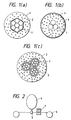
- a communication line material is sent by pressure so as to be laid into a duct line laid in advance, by means of an air flow, for example, by using a pressure-sending apparatus 31 shown in Fig. 3.
- a feed head 34 is attached on an end portion of the duct line 32; drive wheels 35 and 36 send a communication line material 33; and an air lead-in inlet 37 leads in air for sending the communication line material 33 by pressure.
- an air seal 38 prevents leakage of air from an inlet portion of the feed head 34 for the communication line material 33.
- the air seal 38 is provided because the duct line 32 is so long that there is a large loss of pressure.
- a bundle of seven optical fibers 41 are coated by a polypropylene layer 42, and the polypropylene layer 42 is coated with a foam polyethylene layer 43.
- foam polyethylene is used to form the foam polyethylene layer 43 of the communication line material 33
- a problem results because the foam polyethylene is apt to be influenced by the cooling temperature, the temperature distribution in the inside of the extruded material, or dimensional variations in the under-layer to be coated. That is, there is a problem either because the degree of foaming of the foam polyethylene is apt to vary, thereby changing the outer diameter of the foam polyethylene layer 43, or because the thickness of the foam layer is apt to vary as a result of the circumferential temperature distribution in the die which extrudes the layer. As a result, for example, there is a problem of blocking at the portion of the air seal 38 of the pressure-sending apparatus.
- the method according to the present invention contrives to form the coated communication line material to be laid by sending it under pressure through an already laid duct line, wherein the coating material comprises at least one coating layer formed of a composition of energy-beam setting resin in which fluid-encapsulating, hollow spheres are mixed.
- the hollow spheres to be used according to the present invention may be any spheres so long as each of them encapsulates air or another gas or a liquid such as nitrogen, argon, isobutane and has an outer shell portion made of thermoplastic resin such as a copolymer of vinylidene chloride and acrylate, polyethylene, fluororesin; thermosetting resin such as epoxy resin, phenol resin, urea resin, or the like; or an inorganic group material such as silica, alumina, carbon, zirconia, the denatured forms thereof.
- the surface thereof may be treated with a silane coupling agent or the like.
- hollow spheres which have a shell of thermoplastic resin, especially a copolymer of vinylidene chloride and acrylonitrile.
- a diameter of 1-50 ⁇ m and a shell thickness of not larger than 0.5 ⁇ m for each hollow sphere are preferred in order to realize a thin and uniform coating layer having a thickness of 200 ⁇ m or less. Within these limits, the coating layer does not lose its smoothness.
- Examples of energy-beam setting resin compositions include thermosetting resin, ultraviolet setting resin, electron-beam setting resin, and the like.
- ultraviolet setting resin having a high setting speed is preferred because this resin forms coating at a high speed and requires no large-sized setting apparatus.
- Examples of such energy-beam setting resins include, for example, silicone resin, epoxy resin, urethane resin, polyester resin, epoxy acrylate resin, urethane acrylate, acrylate fluoride, silicone acrylate, polyester acrylate, butadiene acrylate.
- the energy-beam setting resins which may be used are not particularly limited to this list of examples.
- a photoinitiator in order to increase the stability and functional properties of coating resin, to add to the resin one or more of the following materials: a photoinitiator, a sensitizer, an antioxidant, a photo-stabilizer, a resin coupling agent, a surface treatment agent, a particle dispersant, or the like, all of which are generally added to materials of the kinds described above.
- the ratio of the hollow spheres in the mixture to the energy-beam setting resin may be freely selected according to the hardness of the target coating layer desired. However, it is desirable to select the volume percent of the hollow spheres relative to the produced resin composition to be 30 - 70 % in order to raise the break strength and to achieve the beneficial effects of the gas or liquid portions (hereinafter, referred to as pores) in the inside of the shells of the hollow spheres.
- a viscosity of the coating resin composition of within a range of 100 - 100,000 cps. It is particularly desirable to select the viscosity to be within the viscosity range of 1000 -10,000 cps in order to easily perform the coating.
- an ultraviolet setting resin in which the viscosity can be freely selected is suitable for obtaining a resin coating composition which has a viscosity within the above viscosity range.
- the coating thickness is not limited but can be freely selected in accordance with the target stress absorption effect, the target bulk density, and the like, it is desirable to select the thickness to be 500 ⁇ m or less in order to harden the energy-beam setting resin sufficiently.
- the flowability of the resin inside the die is so excellent that problems with pressure distribution are almost completely avoided.
- the productivity can be improved. Furthermore, since the selection of the possible material compositions which can be used is large, material can be selected for particular qualities such as adhesion to an under-layer, the hardness of a coating layer.
- pores are formed by hollow spheres so that the concentration of pores (obtained from a difference in specific gravity between the resin containing hollow spheres and resin containing no hollow spheres), which is the concentration of hollow spheres, is set to a predetermined value.
- the outer diameter of a line material can be set to a predetermined value, the problems of variation in thickness in line material can be alleviated, and a light-weight line material with a large surface area can be obtained.
- the present invention it is possible to change the hardness of the whole coating layer by changing the specific concentrations of any of the various types of pores in the resin, each type having different physical properties, so that the transmission characteristics can be changed over a wide range.
- the concentration of pores can be controlled not only by changing the quantity of hollow spheres but also by heating the hollow spheres so as to expand the spheres. It is desirable that such heating to expand the hollow spheres be performed simultaneously with an application of a setting energy-beam to the energy-beam setting resin in order to maintain the shape of the expanded hollow spheres.
- a preferred embodiment of the process used to harden the resin coating comprises passing the ultraviolet setting resin coated material under an ultraviolet lamp, 30 cm in length, at a speed of 25 m/min.
- Another preferred embodiment of the hardening process which combines hardening with heating, comprises passing the ultraviolet setting resin coated material through an oven, 50 cm in length and with a temperature of 300°C, while, either simultaneously with or immediately after the heating, applying ultraviolet light by means of a 30 cm ultraviolet lamp at a speed of 50 cm/min.
- the oven may be, but is not limited to, an electric furnace or an infrared beam emitter.
- the infrared beam emitter functions with a resin composition which is able to generate heat upon exposure to an infrared beam.
- FIG. 1 The diagrams (a), (b), and (c) of Fig. 1 show cross sections of the communication line materials related to Examples 1, 2, and 3.
- Fig. 1 Shown in the diagram (a) of Fig. 1 were seven optical fibers 1, which were arranged such that one central optical fiber was surrounded by six optical fibers and were extrusion-coated with an under-coating 2 of polypropylene (nylon, as well as the same ultraviolet setting resins used for the outer coating can also be used as under-coating) so as to have an outer diameter of 1mm as in the case of Fig. 4 and a coating 3 of energy-beam setting resin with hollow spheres was formed on the under-coating 2.
- polypropylene nylon, as well as the same ultraviolet setting resins used for the outer coating can also be used as under-coating
- Expan-Cell DU (registered trademark; produced by Chemanode Inc.) was used as the hollow sphere, in which isobutane was encapsulated by a shell of a vinylidene chloride-acrylonitrile copolymer.
- the hollow spheres were added and dispersed in ultraviolet setting resin (950X100: produced by Desoto Inc. in U.S.) containing urethane acrylate as a principal component with 50 volume percent, and the thus obtained composition was used as the energy-beam setting resin with hollow spheres.
- ultraviolet setting resin 950X100: produced by Desoto Inc. in U.S.
- the resin was hardened by passing it under an ultraviolet emission apparatus so that the outer diameter of the coating was formed to be 2mm.
- the weight of the hollow sphere coating layer of the line material formed as described above was 1.2g/m.
- the weight of the hollow sphere coating layer of the line material was light in comparison to the weight of the conventional light foam polyethylene layer.
- the communication line material in this example had a difference between the maximum and minimum diameters at any particular place on the communication line of about 10 ⁇ m. This was in contrast to the conventional coating of foam polyethylene layer in which the outer diameters of the six outer optical fibers tended to become large and there was a difference of about 100 ⁇ m between the maximum and minimum diameters at any particular place on the communication line.
- the variation in thickness was very small, and a displacement between the center of the central optical fiber 1 and the center of the outer-circumferential circle of the outermost coating layer was a value of about 5 ⁇ m which was within the range of a measurement error.
- coating can be made at a line speed of 60 m/min or more in this example, while the line speed of coating with foam polyethylene layer in the conventional case is 10 m/sec.
- an ultraviolet lamp 7 is provided between a die 5 of a resin feeding machine 4 and a take-up machine 6. This method does not require the long cooling line which is used in the conventional method (see Fig. 5). Accordingly, it is possible to obtain remarkable reduction in space.
- the communication line material according to the diagram (b) of Fig. 1 was formed in such a manner that optical fibers 1, each having a diameter of 250 ⁇ m, were twisted together, the same energy-beam setting resin coating 3 with hollow spheres as that of the first example was formed on the optical fibers 1 so as to have an outer diameter of 1.6 mm, and the energy-beam setting resin coating 3 was coated with a smooth layer 4 having a thickness of 5 ⁇ m.
- the coating of the smooth layer 4 was formed by adding silicone oil (SH-190 type, made by Toshiba Silicone Co., Ltd.) constituting 0.1 volume % of the same ultraviolet-ray setting resin as described above.
- silicone oil SH-190 type, made by Toshiba Silicone Co., Ltd.
- the three optical fibers 1, which were only twisted together and not undercoated were coated with energy-beam setting resin with hollow spheres. Even in the case of a cross section having a special shape, as shown in this example, an excellent coating layer can be formed because the viscosity of the resin is low. Further, since adhesion of foam polyethylene to another material is poor, it has been conventionally impossible to provide such a smooth layer 4 as in this example.
- a communication line material according to diagram (c) of Fig. 1 was formed in such a manner that three bundles of fibers each composed of seven optical fibers 1 coated with an under-coating 2 of polypropylene in the same manner as in the first example and each having a diameter of 1 mm were brought together and collectively coated with a coating 3 of energy-beam setting resin with hollow spheres so as to have an outer diameter of 5 mm. Also in this case, a very excellent coating layer was formed.
- seven optical fibers 7 arranged as shown in the diagram (a) of Fig. 1 such that one central optical fiber 1 was surrounded by six other optical fibers 6 were extrusion-coated with an under-coating 2 of polypropylene as described above so as to have an outer diameter 2 of 1 mm. Then, the energy-beam setting resin with hollow spheres shown in the first example was applied over the under-coating 2, and irradiated with ultraviolet rays while applying heat in an oven at 300 °C.
- the hollow spheres were expanded by internal gas pressure during the process of hardening, and rapidly cooled when the material was taken out of the oven, so that the hollow spheres were fixed in the expanded state.
- the volume percent of the hollow spheres in the resin presumed from the ratio of the specific gravity of the coating material with hollow spheres before and after application of coating was 70 volume percent.
- the thickness of the energy-beam setting resin was controlled so that the diameter of the coating layer was 2mm, the weight of the coating layer including the hollow spheres could be reduced to 0.7 g/m which was smaller than that of Example 1.
- Such a light-weight line material is extremely advantageous in the aspect of ease of insertion into a duct line, because the weight of a line material acts as resistance against insertion. Further, in the thus produced line material, since hollow spheres are expanded by heat from the surface, the state of expansion is distributed in the outward direction of thickness so that the structure is more dense as the position comes near to the central optical fiber. That is, since no longitudinally uneven force is exerted on the optical fibers and the surface is remarkably expanded so as to practically preclude the appearance of convex portions, therefore, the surface area which contacts with the duct line is decreased and the surface area for receiving a carrying force is increased.
Landscapes
- Physics & Mathematics (AREA)
- General Physics & Mathematics (AREA)
- Optics & Photonics (AREA)
- Light Guides In General And Applications Therefor (AREA)
- Optical Fibers, Optical Fiber Cores, And Optical Fiber Bundles (AREA)
- Paints Or Removers (AREA)
Claims (7)
- Procédé pour former un substrat revêtu de résine, comprenant :caractérisé en ce que :la préparation d'un substrat avec une ou plusieurs fibres optiques (1) ;le revêtement du substrat avec un mélange (3) d'un matériau de type résine durcissable par faisceau d'énergie et d'une pluralité de sphères creuses ; etle durcissement du substrat revêtu par exposition du substrat revêtu à un faisceau d'énergie pendant un laps de temps et avec une quantité d'énergie suffisants pour durcir le matériau de type résine ;les sphères creuses sont choisies de façon à être des sphères creuses encapsulant un fluide et dilatables à chaud ; etledit substrat revêtu est chauffé pour que les sphères creuses soient dilatées en même temps qu'a lieu ledit durcissement par exposition à un faisceau d'énergie.
- Procédé selon la revendication 1, dans lequel ladite étape de durcissement est réalisée par exposition du substrat revêtu à une lumière provenant d'une lampe à ultraviolets.
- Procédé selon la revendication 1, dans lequel ladite étape de chauffage est réalisée par exposition dudit substrat revêtu à une lumière provenant d'un émetteur de faisceaux infrarouges.
- Procédé selon la revendication 1, dans lequel ladite étape de chauffage est réalisée par exposition du substrat revêtu à un faisceau d'énergie provenant d'un four électrique.
- Procédé selon la revendication 1, dans lequel le substrat est recouvert d'une couche de polymère thermoplastique (2) avant le revêtement du substrat avec le mélange dudit matériau de type résine durcissable par faisceau d'énergie et desdites sphères creuses encapsulant un fluide et dilatables à chaud.
- Procédé selon la revendication 5, dans lequel le substrat est recouvert d'un polymère d'oléfine par extrusion.
- Procédé selon la revendication 1, dans lequel le mélange appliqué au substrat a une viscosité de 100 à 100 000 cP.
Applications Claiming Priority (2)
| Application Number | Priority Date | Filing Date | Title |
|---|---|---|---|
| JP2033866A JPH03238410A (ja) | 1990-02-16 | 1990-02-16 | 通信用線材 |
| JP33866/90 | 1990-02-16 |
Publications (3)
| Publication Number | Publication Date |
|---|---|
| EP0442308A2 EP0442308A2 (fr) | 1991-08-21 |
| EP0442308A3 EP0442308A3 (en) | 1993-02-24 |
| EP0442308B1 true EP0442308B1 (fr) | 1998-06-10 |
Family
ID=12398429
Family Applications (1)
| Application Number | Title | Priority Date | Filing Date |
|---|---|---|---|
| EP91100995A Expired - Lifetime EP0442308B1 (fr) | 1990-02-16 | 1991-01-25 | Matériau pour lignes de communication |
Country Status (5)
| Country | Link |
|---|---|
| US (2) | US5441813A (fr) |
| EP (1) | EP0442308B1 (fr) |
| JP (1) | JPH03238410A (fr) |
| AU (1) | AU641725B2 (fr) |
| DE (1) | DE69129554D1 (fr) |
Families Citing this family (25)
| Publication number | Priority date | Publication date | Assignee | Title |
|---|---|---|---|---|
| JPH03238410A (ja) * | 1990-02-16 | 1991-10-24 | Sumitomo Electric Ind Ltd | 通信用線材 |
| CA2110800C (fr) * | 1991-07-01 | 2000-10-24 | Philip Alfred Barker | Fibres optiques |
| US6054651A (en) * | 1996-06-21 | 2000-04-25 | International Business Machines Corporation | Foamed elastomers for wafer probing applications and interposer connectors |
| US5761363A (en) * | 1996-03-07 | 1998-06-02 | Siecor Corporation | Optical fiber ribbon which is strippable and peelable |
| US5814768A (en) * | 1996-06-03 | 1998-09-29 | Commscope, Inc. | Twisted pairs communications cable |
| AU1347699A (en) * | 1997-11-14 | 1999-06-07 | Stewart Group, Inc., The | Coating and filling of cable cores using photocurable polymers |
| US6048911A (en) * | 1997-12-12 | 2000-04-11 | Borden Chemical, Inc. | Coated optical fibers |
| US7026635B2 (en) | 1999-11-05 | 2006-04-11 | Energy Sciences | Particle beam processing apparatus and materials treatable using the apparatus |
| US6409017B1 (en) | 2000-06-30 | 2002-06-25 | Corning Incorporated | Use of inhibitor in optical fiber reel covers |
| DE20016527U1 (de) * | 2000-09-23 | 2000-11-30 | Alcatel, Paris | Elektrische Installationsleitung |
| US6602601B2 (en) | 2000-12-22 | 2003-08-05 | Corning Incorporated | Optical fiber coating compositions |
| GB2376959A (en) * | 2001-06-28 | 2002-12-31 | Autoliv Dev | Tumescent filaments and yarns |
| US6956068B2 (en) * | 2001-11-05 | 2005-10-18 | Radio Frequency Systems, Inc. | Microcellular foam dielectric for use in transmission lines |
| US6801696B2 (en) * | 2002-06-07 | 2004-10-05 | Fitel Usa Corp. | Fiber optic cable structure and method |
| AU2007209832B8 (en) * | 2002-08-10 | 2009-08-13 | Emtelle Uk Limited | Signal Transmitting Cable |
| GB0313017D0 (en) * | 2002-08-10 | 2003-07-09 | Emtelle Uk Ltd | Signal transmitting cable |
| GB0313018D0 (en) | 2002-08-10 | 2003-07-09 | Emtelle Uk Ltd | Signal transmitting cable |
| GB2409908C (en) * | 2002-08-10 | 2011-07-13 | Emtelle Uk Ltd | Signal transmitting cable |
| US8124661B2 (en) * | 2003-06-20 | 2012-02-28 | Northrop Grumman Guidance And Electronics Company, Inc. | Introducing voids into polymeric material for buffering one or more stress sensitive components from one or more stresses |
| US7247796B2 (en) * | 2003-10-28 | 2007-07-24 | 3M Innovative Properties Company | Filling materials |
| KR20050051302A (ko) * | 2003-11-27 | 2005-06-01 | 삼성전자주식회사 | 광섬유 케이블과 광섬유 케이블의 제작 방법 |
| US20070001388A1 (en) * | 2005-06-17 | 2007-01-04 | Lexmark International, Inc. | Media feeding management |
| US7785509B2 (en) * | 2005-12-21 | 2010-08-31 | Pascale Industries, Inc. | Expansible yarns and threads, and products made using them |
| US20110100667A1 (en) * | 2009-11-04 | 2011-05-05 | Peter Hardie | Audio cable with vibration reduction |
| JP7773428B2 (ja) * | 2022-04-13 | 2025-11-19 | 古河電気工業株式会社 | 光ファイバケーブル |
Family Cites Families (28)
| Publication number | Priority date | Publication date | Assignee | Title |
|---|---|---|---|---|
| US3479811A (en) * | 1967-11-29 | 1969-11-25 | Dow Chemical Co | Yarn and method of making the same |
| US3565685A (en) * | 1968-11-29 | 1971-02-23 | Matsushita Electric Industrial Co Ltd | Insulated conductors and method of manufacture thereof |
| US3769126A (en) * | 1970-01-30 | 1973-10-30 | Westinghouse Electric Corp | Resinous-microsphere-glass fiber composite |
| US3683104A (en) * | 1971-01-07 | 1972-08-08 | Dow Chemical Co | Heat resistant cable |
| JPS5125580Y2 (fr) * | 1971-11-18 | 1976-06-29 | ||
| US3922442A (en) * | 1972-06-01 | 1975-11-25 | Nat Distillers Chem Corp | Flame retardant compositions |
| US4125487A (en) * | 1977-05-23 | 1978-11-14 | The Dow Chemical Company | Non-cellular and cellular composites of polyurethanes and vinyl polymers |
| NL7706283A (nl) * | 1977-06-08 | 1978-12-12 | Akzo Nv | Werkwijze voor het bekleden van een voorwerp uit een gevulkaniseerde polyalkeenrubber. |
| US4265972A (en) * | 1979-03-09 | 1981-05-05 | Bernard Rudner | Coated fibers and related process |
| US4303736A (en) * | 1979-07-20 | 1981-12-01 | Leonard Torobin | Hollow plastic microspheres |
| US4382821A (en) * | 1980-05-02 | 1983-05-10 | Siecor Corporation | Filling materials for communications cable |
| US4324453A (en) * | 1981-02-19 | 1982-04-13 | Siecor Corporation | Filling materials for electrical and light waveguide communications cables |
| JPS58194762A (ja) * | 1982-05-11 | 1983-11-12 | Toray Silicone Co Ltd | 光通信ガラスフアイバ用被覆材 |
| US4514037A (en) * | 1983-10-21 | 1985-04-30 | Desoto, Inc. | Ultraviolet curable outer coatings for optical fiber |
| US4522465A (en) * | 1983-11-10 | 1985-06-11 | Desoto, Inc. | Optical fiber coated with an ultraviolet cured topcoating |
| JPS60223831A (ja) * | 1984-04-23 | 1985-11-08 | Sanyo Kokusaku Pulp Co Ltd | ポリプロピレン系樹脂用硬化塗料組成物 |
| US4572610A (en) * | 1984-05-21 | 1986-02-25 | Desoto, Inc. | Optical fiber buffer coated with halogenated dihydroxy-terminated polybutadienes |
| US4608409A (en) * | 1985-05-08 | 1986-08-26 | Desoto, Inc. | Polyacrylated oligomers in ultraviolet curable optical fiber coatings |
| DE3522751C2 (de) * | 1985-06-26 | 1997-02-06 | Henkel Kgaa | Kabelfüllmassen |
| JPS62119141A (ja) * | 1985-11-19 | 1987-05-30 | Shin Etsu Chem Co Ltd | 放射線硬化性光フアイバ−用被覆剤 |
| US4854666A (en) * | 1987-02-04 | 1989-08-08 | Mitsui Toatsu Chemicals, Incorporated | Photosetting resin composition |
| JPS6460648A (en) * | 1987-08-28 | 1989-03-07 | Junkosha Co Ltd | Low-permittivity composite material |
| US4879163A (en) * | 1987-09-24 | 1989-11-07 | Bay Mills Limited | Textiles containing interstices and processes for making such textiles |
| US4877306A (en) * | 1987-09-30 | 1989-10-31 | Corning Glass Works | Coated optical waveguide fibers |
| FR2622024B1 (fr) * | 1987-10-16 | 1990-01-19 | Comp Generale Electricite | Procede de fabrication d'un cable a fibre optique et cable obtenu par ce procede |
| GB8911959D0 (en) * | 1988-05-28 | 1989-07-12 | Ici Plc | Coated optical fibres |
| TW297798B (fr) * | 1989-03-15 | 1997-02-11 | Sumitomo Electric Industries | |
| JPH03238410A (ja) * | 1990-02-16 | 1991-10-24 | Sumitomo Electric Ind Ltd | 通信用線材 |
-
1990
- 1990-02-16 JP JP2033866A patent/JPH03238410A/ja active Pending
-
1991
- 1991-01-25 EP EP91100995A patent/EP0442308B1/fr not_active Expired - Lifetime
- 1991-01-25 DE DE69129554T patent/DE69129554D1/de not_active Expired - Lifetime
- 1991-02-15 AU AU71107/91A patent/AU641725B2/en not_active Ceased
-
1994
- 1994-08-16 US US08/291,732 patent/US5441813A/en not_active Expired - Lifetime
-
1995
- 1995-06-01 US US08/457,144 patent/US5562985A/en not_active Expired - Lifetime
Also Published As
| Publication number | Publication date |
|---|---|
| AU641725B2 (en) | 1993-09-30 |
| US5562985A (en) | 1996-10-08 |
| DE69129554D1 (de) | 1998-07-16 |
| US5441813A (en) | 1995-08-15 |
| EP0442308A2 (fr) | 1991-08-21 |
| EP0442308A3 (en) | 1993-02-24 |
| AU7110791A (en) | 1991-08-22 |
| JPH03238410A (ja) | 1991-10-24 |
Similar Documents
| Publication | Publication Date | Title |
|---|---|---|
| EP0442308B1 (fr) | Matériau pour lignes de communication | |
| CA2005286C (fr) | Conducteur isole et methode de fabrication connexe | |
| US5062685A (en) | Coated optical fibers and cables and method | |
| CA1301421C (fr) | Methode de moulage en continu, pour la fabrication de produits en forme de tige | |
| EP0168774B1 (fr) | Corde composée et sa fabrication | |
| JP3176390B2 (ja) | 強化プラスチック製鎧装ケーブルの製造方法 | |
| CA2012282C (fr) | Fil electrique isole et mode de fabrication | |
| US6574400B1 (en) | Fiber optic cable with water blocking features | |
| US4305770A (en) | Fabrication of fiber reinforced resin structures | |
| AU654209B2 (en) | Optical fiber including acidic coating system | |
| CA2238643A1 (fr) | Cable optique et composante de celui-ci | |
| US7450805B2 (en) | Optical fiber unit for air blown installation and manufacturing method thereof | |
| CN111965776A (zh) | 一种螺旋微槽型气吹微缆、制造设备及制造方法 | |
| CA1280306C (fr) | Cable de telecommunication a fibres optiques | |
| US20040060609A1 (en) | Monolayer foamed corrugated sleeve | |
| US4699579A (en) | Apparatus for making an extruded composite structure | |
| JPS61144323A (ja) | 被覆材の溶融温度に敏感な心材の被覆装置および被覆方法 | |
| EP0646275B1 (fr) | Procede de traitement thermique d'un cable | |
| JP3821930B2 (ja) | 光ファイバ担持用スペーサ | |
| WO2005057263A1 (fr) | Element de tension en frp pour cable de derivation a fibre optique | |
| JP2563957B2 (ja) | 可撓性光導波路の製造方法 | |
| JPH03268927A (ja) | 光ファイバ担持用繊維強化硬化性樹脂製スペーサの製造方法 | |
| JPH09197221A (ja) | 光ファイバ圧送用ユニット及びその製法 | |
| JP2789645B2 (ja) | 絶縁電線とその製造方法 | |
| JP3383565B2 (ja) | 光ファイバテープ心線の製造方法 |
Legal Events
| Date | Code | Title | Description |
|---|---|---|---|
| PUAI | Public reference made under article 153(3) epc to a published international application that has entered the european phase |
Free format text: ORIGINAL CODE: 0009012 |
|
| AK | Designated contracting states |
Kind code of ref document: A2 Designated state(s): DE FR GB NL SE |
|
| PUAL | Search report despatched |
Free format text: ORIGINAL CODE: 0009013 |
|
| AK | Designated contracting states |
Kind code of ref document: A3 Designated state(s): DE FR GB NL SE |
|
| 17P | Request for examination filed |
Effective date: 19930608 |
|
| 17Q | First examination report despatched |
Effective date: 19950824 |
|
| GRAG | Despatch of communication of intention to grant |
Free format text: ORIGINAL CODE: EPIDOS AGRA |
|
| GRAG | Despatch of communication of intention to grant |
Free format text: ORIGINAL CODE: EPIDOS AGRA |
|
| GRAG | Despatch of communication of intention to grant |
Free format text: ORIGINAL CODE: EPIDOS AGRA |
|
| GRAH | Despatch of communication of intention to grant a patent |
Free format text: ORIGINAL CODE: EPIDOS IGRA |
|
| GRAH | Despatch of communication of intention to grant a patent |
Free format text: ORIGINAL CODE: EPIDOS IGRA |
|
| GRAA | (expected) grant |
Free format text: ORIGINAL CODE: 0009210 |
|
| AK | Designated contracting states |
Kind code of ref document: B1 Designated state(s): DE FR GB NL SE |
|
| PG25 | Lapsed in a contracting state [announced via postgrant information from national office to epo] |
Ref country code: NL Free format text: LAPSE BECAUSE OF FAILURE TO SUBMIT A TRANSLATION OF THE DESCRIPTION OR TO PAY THE FEE WITHIN THE PRESCRIBED TIME-LIMIT Effective date: 19980610 |
|
| REF | Corresponds to: |
Ref document number: 69129554 Country of ref document: DE Date of ref document: 19980716 |
|
| PG25 | Lapsed in a contracting state [announced via postgrant information from national office to epo] |
Ref country code: SE Free format text: LAPSE BECAUSE OF FAILURE TO SUBMIT A TRANSLATION OF THE DESCRIPTION OR TO PAY THE FEE WITHIN THE PRESCRIBED TIME-LIMIT Effective date: 19980910 |
|
| PG25 | Lapsed in a contracting state [announced via postgrant information from national office to epo] |
Ref country code: DE Free format text: LAPSE BECAUSE OF FAILURE TO SUBMIT A TRANSLATION OF THE DESCRIPTION OR TO PAY THE FEE WITHIN THE PRESCRIBED TIME-LIMIT Effective date: 19980911 |
|
| ET | Fr: translation filed | ||
| NLV1 | Nl: lapsed or annulled due to failure to fulfill the requirements of art. 29p and 29m of the patents act | ||
| PLBE | No opposition filed within time limit |
Free format text: ORIGINAL CODE: 0009261 |
|
| STAA | Information on the status of an ep patent application or granted ep patent |
Free format text: STATUS: NO OPPOSITION FILED WITHIN TIME LIMIT |
|
| 26N | No opposition filed | ||
| PGFP | Annual fee paid to national office [announced via postgrant information from national office to epo] |
Ref country code: GB Payment date: 20010124 Year of fee payment: 11 |
|
| PGFP | Annual fee paid to national office [announced via postgrant information from national office to epo] |
Ref country code: FR Payment date: 20010125 Year of fee payment: 11 |
|
| REG | Reference to a national code |
Ref country code: GB Ref legal event code: IF02 |
|
| PG25 | Lapsed in a contracting state [announced via postgrant information from national office to epo] |
Ref country code: GB Free format text: LAPSE BECAUSE OF NON-PAYMENT OF DUE FEES Effective date: 20020125 |
|
| GBPC | Gb: european patent ceased through non-payment of renewal fee |
Effective date: 20020125 |
|
| PG25 | Lapsed in a contracting state [announced via postgrant information from national office to epo] |
Ref country code: FR Free format text: LAPSE BECAUSE OF NON-PAYMENT OF DUE FEES Effective date: 20020930 |
|
| REG | Reference to a national code |
Ref country code: FR Ref legal event code: ST |