EP0442351A1 - Capteur de températures aux infrarouges - Google Patents
Capteur de températures aux infrarouges Download PDFInfo
- Publication number
- EP0442351A1 EP0442351A1 EP91101518A EP91101518A EP0442351A1 EP 0442351 A1 EP0442351 A1 EP 0442351A1 EP 91101518 A EP91101518 A EP 91101518A EP 91101518 A EP91101518 A EP 91101518A EP 0442351 A1 EP0442351 A1 EP 0442351A1
- Authority
- EP
- European Patent Office
- Prior art keywords
- temperature sensor
- signal
- infrared temperature
- sensor according
- processing device
- Prior art date
- Legal status (The legal status is an assumption and is not a legal conclusion. Google has not performed a legal analysis and makes no representation as to the accuracy of the status listed.)
- Granted
Links
Images


Classifications
-
- G—PHYSICS
- G01—MEASURING; TESTING
- G01J—MEASUREMENT OF INTENSITY, VELOCITY, SPECTRAL CONTENT, POLARISATION, PHASE OR PULSE CHARACTERISTICS OF INFRARED, VISIBLE OR ULTRAVIOLET LIGHT; COLORIMETRY; RADIATION PYROMETRY
- G01J5/00—Radiation pyrometry, e.g. infrared or optical thermometry
- G01J5/10—Radiation pyrometry, e.g. infrared or optical thermometry using electric radiation detectors
- G01J5/12—Radiation pyrometry, e.g. infrared or optical thermometry using electric radiation detectors using thermoelectric elements, e.g. thermocouples
Definitions
- the invention relates to an infrared temperature sensor with a sensor element that generates an analog output signal, which is converted into a digital signal and processed.
- Such infrared temperature sensors are used in radiation pyrometers for non-contact temperature measurement. They are particularly suitable for measuring very high temperatures, which could only be determined with great effort using contact temperature measuring methods.
- the radiation pyrometers work either with manually adjustable measurement parameters or with fixed measurement parameters, which result in little flexibility in the applicability of the radiation pyrometers.
- Japanese patent application JP 61-30 728 Patent Abstracts of Japan, Vol. 10 / No. 183; P-472, June 26, 1986
- a detector is rotatably suspended, the speed of rotation being regulated as a function of the output signal of the detector.
- JP A 61-186824 Patent Abstracts of Japan, P Vol. 11 / No. 9; P-534, January 10, 1987.
- an output signal is fed as a function of the size of the measuring signal to various amplifiers, which causes the measuring range to be set automatically.
- the invention provides an infrared temperature sensor which has a converter device for converting the analog output signal of the sensor element into a digital signal.
- the converter device consists of a voltage / frequency converter, which is followed by an adjustable frequency counter.
- an adjustable frequency counter As a result, not only the measuring range but also the resolution or the measuring speed can be adapted to the individual requirements of the infrared temperature sensor.
- the analog output signal of the sensor element is digitized early on before it is evaluated and linearized, it being possible to choose between a very high resolution and a lower measuring speed or between a lower resolution and a high measuring speed due to the selectable resolution of the converter device .
- the infrared temperature sensor is therefore suitable for a wide range of measuring tasks and can therefore be used at various measuring stations without any problems.
- infrared temperature sensor Another advantage of the infrared temperature sensor is that the linearization and evaluation of the output signal take place after the digitization of the output signal generated by the sensor element. As a result, expensive analog circuits and compensation resistors for temperature compensation are avoided by means of complex linearization devices, which represent a potential source of error when the infrared temperature sensor is used at different ambient temperatures.
- the measuring range can also be program-controlled.
- the invention is particularly suitable for measuring deforming or moving objects.
- the converter device is formed from a voltage / frequency converter and a downstream, adjustable frequency counter.
- the analog output signal generated by the sensor element is converted into a pulse train, the frequency of which depends on the amplitude of the output signal.
- the frequency counter which can be set, is then used depending on the desired frequency counter Resolution the gate time varies, creating a digital signal that can be processed in the digital signal processing device.
- the resolution of the frequency counter is programmable via the signal processing device.
- a temperature sensor which generates a temperature-dependent reference junction signal is advantageously arranged in the immediate vicinity of the sensor element in order to compensate for temperature influences on the sensor element.
- a control voltage source can advantageously be provided for generating a reference signal, on the basis of which temperature influences on the evaluation circuit can be checked and compensated.
- connection for a contact temperature sensor is also provided, on the basis of which the emission factor can be determined.
- the above-mentioned measurement and reference variables can either be alternately connected to the input of the adjustable converter device and / or distributed over several inputs of the signal processing device via a program-controlled changeover switch.
- the converter device and the switch are controlled by means of a control logic which is implemented in a microprocessor of the signal processing device.
- the digital signal processing device is advantageously provided with a plurality of inputs and outputs. Several analog / digital converters can thus be provided as inputs for analog signals and reference voltages.
- An internal bus (I2C bus) is provided for the communication of the signal processing device with input and output devices on site, e.g. to control a display, to connect a keyboard to change measurement parameters etc.
- the signal processing device of the infrared temperature sensor has a connection for an external bus system for input and output, via which the signal processing device can in particular be controlled and programmed.
- a plurality of temperature sensors and other measuring devices can be centrally controlled by a central control unit, reprogramming of the measurement parameters or the linearization data, for example, being possible from the central control unit.
- the central control unit can be formed, for example, by a personal computer.
- a two-wire line is excellently suited as a bus system, which enables several measuring stations to be connected with little technical effort, the signals from the measuring stations and the central control unit being able to be carried out by means of a digital identifier, for example using the multiplex method or another coding method.
- the signal processing device is advantageously connected to the external bus system via an optocoupler in order to avoid the transmission of interference between the bus system and the digital signal processing device.
- the voltage supply of the signal processing device is also galvanically isolated from the network by a DC / DC converter if the energy supply is not via a two-wire line.
- the infrared temperature sensor according to the invention creates a measuring device which allows a contactless temperature measurement with a variable sampling rate, an automatic emission factor correction can be carried out via a connectable contact thermometer and which is fieldbus-compatible via interfaces and can communicate with peripheral, higher-level measuring and data processing devices .
- FIG. 1 the longitudinal section through an infrared sensor 10 is shown, which has an elongated, cylindrical housing 12, which consists of corrosion-resistant and shielding against electromagnetic radiation material.
- This housing 12 houses the sensor element, the optics and the electronics of the infrared temperature sensor.
- the housing 12 has a holder at its front longitudinal end 14, which is held in the housing 12 with a thread.
- This holder serves to fix the solid disk 16, which consists of a material that is transparent to the desired infrared radiation with the highest possible degree of transmission.
- This solid disk 16 also serves as mechanical impact protection against external influences and as a filter for unwanted radiation.
- This solid disk 16 can also be designed in the manner of a lens as an optically active element.
- the infrared radiation emanating from a measurement object falls through the solid disk 16 onto a reflector mirror 18, through which the radiation is focused onto a detector 20 which has a sensor element designed as a thermopile and a temperature sensor.
- This detector 20 also has a filter window suitable for the radiation to be detected.
- An annular diaphragm 22 is arranged in front of the detector 20 and serves to avoid edge radiation which could distort the measurement result as interference radiation.
- the detector 20 is held in the focal point of the focusing reflector mirror 18 by means of a holder 24. This holder 24 is also used for thermal and electrical insulation of the detector 20 from the housing 12.
- Sealing rings 26 are provided between the end faces and the tubular part of the housing in order to ensure splash-water tightness for securing the internal electronics and optics.
- two boards 28, 30 are arranged for the converter evaluation and data transmission electronics, which will be described in more detail below.
- the rear end wall of the housing is formed by a plastic film-coated rear wall 32, in the center of which a multipole, watertight plug 34 is arranged for connecting the infrared sensor to the supply voltage and to a signal data line.
- This connector also contains connections for analog outputs and peripheral devices.
- the rear wall 32 also has an infrared transmission element 36, which is provided for remote control of the infrared sensor from an infrared transmission element described below.
- the rear wall 32 has a combined plug device 38 for a surface temperature sensor with an integrated contact for starting an automatic emission factor determination.
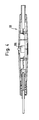
- the temperature sensor is described in more detail in FIG. 4.
- FIG. 2 shows the block diagram of the infrared temperature sensor 10 from FIG. 1.
- the optical focusing device designed as a reflector mirror 18 is shown on the left side of the block diagram. From there, the incoming infrared rays fall on the detector 20, which has a sensor element 40 designed as a thermopile and a temperature sensor 42 designed as a thermistor, which - like the sensor element 40 - generates an analog output signal.
- the connections of the thermopile 40 and the thermistor 42 are controlled together with the output of a reference voltage source 44 for self-calibration of the infrared temperature sensor Channel selector switch 46 placed.
- the measurement signal of the thermopile 40, the reference junction signal of the thermistor 42 and the reference signal of the reference voltage source 44 are applied to a programmable amplifier 48 which operates as a standardization amplifier.
- the output of the amplifier 48 is connected to a voltage / frequency converter 50 which generates a digital signal from the amplified analog signal, the frequency of which depends on the amplitude of the analog signal.
- the digital frequency signal is applied to a first input of a microprocessor 52, which represents the heart of the signal processing device of the infrared temperature sensor 10.
- the first input of the microprocessor 52 is formed by a counter module 54 with variable resolution, in particular between 8 and 16 bits. This makes it possible to determine whether you want to measure with very high resolution or with high speed and lower resolution.
- the microprocessor 52 also has, as a 10-bit analog / digital converter 56, a second input for measuring the temperature of the measurement object 58 via a contact thermometer 60 shown in more detail in FIG. 4 for determining the emission factor.
- the second input of this analog / digital converter 56 is either connected directly to the output of the thermopile or can also be switched between different analog output voltages and possible reference voltages via a program-controlled switch 62. This allows, for example, a quick infrared temperature or cold junction signal measurement due to the parallel analog / digital conversion.
- the input for the contact thermometer 60 is with a constant current source 63 for supplying a resistance thermometer connected in the contact thermometer 60, the output signal of the contact thermometer 60 being fed to the analog / digital converter 56 via an input amplifier 64.
- the emission factor of an unknown radiator can be determined and an automatic emission factor correction can be carried out.
- the detection of the emission factor of a gray emitter is often difficult.
- the method of comparison measurement is often used and then converted to the emission factor, or the temperature determined by the infrared thermometer is set by adjusting the emission factor to be the same as the measured temperature of a contact thermometer.
- the emission factor has to be reset in the known infrared temperature sensor. This can be omitted here, since the result of the surface contact measurement of the measurement object is taken into account immediately for an automatic determination of the emission factor.
- the microprocessor 52 also has a control logic 66 which takes over the control of the channel selector switch 46 and, if appropriate, the switch 62.
- the microprocessor 52 also has an arithmetic logic 68 which carries out the linearization of the measurement signal, the normalization, the comparison point calculation and various compensations.
- an internal interface (I2C bus) 70 designed as a serial bus is provided in the microprocessor 52 in order to be able to output analog signals, in particular on site, for the display of measured values.
- a serial keyboard display extension 72 is connected to the internal bus 70 as an input keyboard and a measured value or status display.
- the internal bus 70 is an emission factor setting 74, an attenuation setting 76, switching outputs 78 and an analog output 80 connected, which consists of a digital / analog converter and an amplifier. This analog output 80 serves as an analog voltage or current output for the analog voltage generated by the sensor element 40.
- the microprocessor 52 is connected to an electrically erasable memory element 82 for storing the sensor parameters (e.g. EEPROM) and other changing operating data. The saved values are retained even in the event of a power failure of the infrared temperature sensor, so that they do not have to be re-entered afterwards.
- the microprocessor 52 is additionally connected to an EPROM and / or RAM 84, which forms the program memory of the signal processing device. This memory can be accessed via an external bus system, which will be described in the following, in order to change the measuring ranges, limit values or analog inputs and outputs.
- the microprocessor 52 is connected via an optocoupler 86 to a serial interface module 88, which in turn is connected to an external bus system 90, which is designed as a two-wire line.
- This two-wire line can be used for energy transmission and data transmission via amplitude modulation or frequency modulation and corresponding commercially available decoupling modules.
- the serial interface module 88 is provided as an interface driver receiver for symmetrical or asymmetrical data transmission with different baud rates (here specifically 76,800 bits / sec).
- a DC-DC converter 92 is provided in the signal processing device, which effects a galvanic isolation for isolating the sensor unit from the network.
- the microprocessor 52 is connected to an infrared transmission unit 36, which provides a transmitter and receiver diode for connection-free, wireless data exchange between the sensor arrangement 10 and an external reader or transmitter unit described in more detail in FIG. 3.
- FIG. 3 shows an example of configuration options for a plurality of infrared temperature sensors 10a, b, c and d, which are connected via the two-wire bus 90 to a higher-level control unit 96 functioning as a master.
- This control unit 96 can be, for example, an intelligent measuring device, a computer or a transmitter.
- the data transmission protocol can be designed in any known manner.
- a keyboard with display 98 is connected to the infrared temperature sensor 10a via the keyboard display extension 72 shown in FIG. 2.
- the infrared temperature sensor 10b is via the infrared transmission unit 36 shown in FIGS. 1 and 2 in transmission contact with a further external control unit 100, which also has an infrared transmission unit in order to control the infrared sensor 10b from a central location and to be able to monitor.
- the analog output 80 of the infrared temperature sensor shown in FIG. 2 10c is connected to a drive 102, which is used for regulation and control functions. The control takes place via the current flow.
- a contact thermometer 60 which measures the temperature of the radiation-emitting measurement object 58, is connected to the infrared temperature sensor 10d. Furthermore, a digital or analog measured value display 104 is connected to the infrared temperature sensor 102d.
- the contact thermometer 60 is shown. It is designed as a stylus and has a button 106, the actuation of which automatically calculates the emission factor. This value is then stored in the electrically erasable memory element 84 in the form of an EEPROM and is used there to calculate future measured values. If a calibration procedure takes place without a contact thermometer, the internally set emission factor is used. The emission factor can of course also be set by the central control unit 96 via the two-wire line 90. This is very advantageous because the infrared temperature sensors are often very inaccessible.
- the temperature sensor in FIG. 2 contains an input module 75 through which a measuring cycle can be triggered with the aid of an external trigger signal.
Landscapes
- Physics & Mathematics (AREA)
- General Physics & Mathematics (AREA)
- Spectroscopy & Molecular Physics (AREA)
- Radiation Pyrometers (AREA)
- Photometry And Measurement Of Optical Pulse Characteristics (AREA)
- Geophysics And Detection Of Objects (AREA)
- Fire-Detection Mechanisms (AREA)
Priority Applications (1)
| Application Number | Priority Date | Filing Date | Title |
|---|---|---|---|
| AT91101518T ATE94639T1 (de) | 1990-02-13 | 1991-02-05 | Infrarot-temperatursensor. |
Applications Claiming Priority (2)
| Application Number | Priority Date | Filing Date | Title |
|---|---|---|---|
| DE4004408A DE4004408A1 (de) | 1990-02-13 | 1990-02-13 | Infrarot-temperatursensor |
| DE4004408 | 1990-12-02 |
Publications (2)
| Publication Number | Publication Date |
|---|---|
| EP0442351A1 true EP0442351A1 (fr) | 1991-08-21 |
| EP0442351B1 EP0442351B1 (fr) | 1993-09-15 |
Family
ID=6400050
Family Applications (1)
| Application Number | Title | Priority Date | Filing Date |
|---|---|---|---|
| EP91101518A Expired - Lifetime EP0442351B1 (fr) | 1990-02-13 | 1991-02-05 | Capteur de températures aux infrarouges |
Country Status (6)
| Country | Link |
|---|---|
| US (1) | US5169234A (fr) |
| EP (1) | EP0442351B1 (fr) |
| JP (1) | JPH0875554A (fr) |
| AT (1) | ATE94639T1 (fr) |
| DE (2) | DE4004408A1 (fr) |
| ES (1) | ES2045963T3 (fr) |
Cited By (4)
| Publication number | Priority date | Publication date | Assignee | Title |
|---|---|---|---|---|
| EP0747682A1 (fr) * | 1995-05-31 | 1996-12-11 | Anritsu Meter Co., Ltd. | Appareil de mesure de température |
| FR2772918A1 (fr) * | 1997-11-21 | 1999-06-25 | Omega Engineering | Appareil portatif pour la mesure de la temperature d'une surface par infrarouges |
| CN101581798B (zh) * | 2009-06-19 | 2011-04-27 | 宁波恒博通讯设备有限公司 | 一种红外线对射装置发送端的红外信号产生方法 |
| WO2013178969A1 (fr) * | 2012-05-26 | 2013-12-05 | Aker Subsea Limited | Procédé et appareil de mesure de l'émissivité et de la densité du pétrole brut |
Families Citing this family (35)
| Publication number | Priority date | Publication date | Assignee | Title |
|---|---|---|---|---|
| US5717608A (en) * | 1994-09-26 | 1998-02-10 | Luxtron Corporation | Electro-optical board assembly for measuring the temperature of an object surface from infra-red emissions thereof, including an automatic gain control therefore |
| US5725308A (en) * | 1994-12-23 | 1998-03-10 | Rtd Technology, Inc. | Quick registering thermometer |
| US5614716A (en) * | 1996-04-26 | 1997-03-25 | Infratemp, Inc. | Alternating current method and apparatus for ambient temperature compensation for modulated energy sensors |
| US5666956A (en) * | 1996-05-20 | 1997-09-16 | Buchert; Janusz Michal | Instrument and method for non-invasive monitoring of human tissue analyte by measuring the body's infrared radiation |
| US5836694A (en) * | 1996-12-10 | 1998-11-17 | Raytek Subsidiary, Inc. | Laser and scope aiming mechanism for a hand-held temperature measuring unit |
| JP2000131146A (ja) * | 1998-10-28 | 2000-05-12 | Omron Corp | 電子温度計 |
| IL134026A (en) * | 2000-01-13 | 2005-11-20 | Visonic Ltd | Circuitry for signal measurement |
| KR20020006135A (ko) * | 2000-07-11 | 2002-01-19 | 이구택 | 복사온도계 신호처리 장치 |
| US6864802B2 (en) | 2000-09-01 | 2005-03-08 | Ut-Battelle, Llc | Wireless spread-spectrum telesensor chip with synchronous digital architecture |
| JP2004151038A (ja) * | 2002-10-31 | 2004-05-27 | Kett Electric Laboratory | 加熱乾燥式赤外線水分計 |
| DE10316885A1 (de) * | 2003-04-12 | 2004-10-28 | Abb Patent Gmbh | Vorrichtung zur Erfassung oder zur Beeinflussung |
| DE10344263A1 (de) * | 2003-09-23 | 2005-05-12 | Conducta Endress & Hauser | Verfahren zur sicheren Datenübertragung zwischen einem eigensicheren Sensor und einer nicht eigensicheren Auswerteeinheit |
| EP2352185A1 (fr) * | 2003-10-28 | 2011-08-03 | Johnson Controls Techonology Company | Enrobage pour une batterie avec répartition de la chaleur ameliorée |
| US20050207470A1 (en) * | 2004-01-26 | 2005-09-22 | Bennett Timothy J | Focusing thermometer |
| US7235779B1 (en) | 2004-10-20 | 2007-06-26 | United States Of America As Represented By The Secretary Of The Air Force | Night vision-weighted irradiance testing |
| US7857507B2 (en) * | 2004-11-16 | 2010-12-28 | Welch Allyn, Inc. | Temperature patch and method of using the same |
| US7815367B2 (en) * | 2004-11-16 | 2010-10-19 | Welch Allyn, Inc. | Multi-site infrared thermometer |
| JP4555148B2 (ja) * | 2005-01-07 | 2010-09-29 | 株式会社キーエンス | 放射温度計 |
| US20070017395A1 (en) * | 2005-07-22 | 2007-01-25 | Neri Joel D | Method and apparatus for uniformly heating a substrate |
| US7391504B1 (en) | 2005-12-14 | 2008-06-24 | The United States Of America As Represented By The Secretary Of The Air Force | Low cost night vision apparatus and cockpit lighting compatibility evaluation via visual acuity |
| US20080218998A1 (en) * | 2007-03-08 | 2008-09-11 | Quest William J | Device having multiple light sources and methods of use |
| US7905855B2 (en) * | 2007-07-05 | 2011-03-15 | Baxter International Inc. | Dialysis system having non-invasive temperature sensing |
| JP4858388B2 (ja) * | 2007-09-28 | 2012-01-18 | ソニー株式会社 | 固体撮像装置、駆動制御方法、および撮像装置 |
| KR101015839B1 (ko) * | 2008-07-28 | 2011-02-23 | 현대모비스 주식회사 | 헤드램프 |
| US20100058837A1 (en) * | 2008-09-05 | 2010-03-11 | Quest William J | Device having multiple light sources and methods of use |
| WO2010048505A1 (fr) * | 2008-10-23 | 2010-04-29 | Kaz, Incorporated | Thermomètre médical sans contact possédant un écran contre les rayonnements parasites |
| US8657758B2 (en) | 2010-12-02 | 2014-02-25 | Welch Allyn, Inc. | Devices and methods for temperature determination |
| EP2551656A1 (fr) * | 2011-07-28 | 2013-01-30 | ABB Technology AG | Dispositif de mesure de température |
| US10575829B2 (en) * | 2014-09-03 | 2020-03-03 | Earlysense Ltd. | Menstrual state monitoring |
| US10172593B2 (en) | 2014-09-03 | 2019-01-08 | Earlysense Ltd. | Pregnancy state monitoring |
| US11013266B2 (en) | 2016-12-09 | 2021-05-25 | Rai Strategic Holdings, Inc. | Aerosol delivery device sensory system including an infrared sensor and related method |
| US11355369B2 (en) | 2018-10-15 | 2022-06-07 | Jongpal AHN | Method of monitoring surface temperatures of wafers in real time in semiconductor wafer cleaning apparatus and temperature sensor for measuring surface temperatures of wafer |
| KR102024206B1 (ko) * | 2019-04-01 | 2019-09-23 | 에이제이텍 주식회사 | 웨이퍼 표면 온도 측정용 적외선 온도센서 |
| JP7249233B2 (ja) * | 2019-07-30 | 2023-03-30 | 倉敷紡績株式会社 | サーモカメラ |
| RU203988U1 (ru) * | 2020-08-11 | 2021-05-04 | Федеральное Государственное Казенное Военное Образовательное Учреждение Высшего Образования "Военный Учебно-Научный Центр Сухопутных Войск "Общевойсковая Ордена Жукова Академия Вооруженных Сил Российской Федерации" | Доплеровский радиоволновый извещатель |
Citations (3)
| Publication number | Priority date | Publication date | Assignee | Title |
|---|---|---|---|---|
| GB2133877A (en) * | 1982-12-24 | 1984-08-01 | Rolls Royce | Generation of a signal dependent upon temperature of gas turbine rotor blades |
| GB2134251A (en) * | 1982-12-24 | 1984-08-08 | Rolls Royce | Optical radiation pyrometer |
| US4634294A (en) * | 1979-09-12 | 1987-01-06 | Raytek, Inc. | Hand-held digital temperature measuring instrument |
Family Cites Families (19)
| Publication number | Priority date | Publication date | Assignee | Title |
|---|---|---|---|---|
| US3501237A (en) * | 1964-04-28 | 1970-03-17 | Ind Dev Fund | Apparatus for and method of determining temperature |
| GB1207984A (en) * | 1967-10-06 | 1970-10-07 | Inst Metallurgii Imeni Aa Baik | Improvements in or relating to radiation measurement |
| GB1340705A (en) * | 1970-04-28 | 1973-12-12 | Lucas Industries Ltd | Apparatus for temperature measurement |
| US3759102A (en) * | 1971-03-25 | 1973-09-18 | Steel Corp | Apparatus for determining correct pyrometer readings with steam interference present |
| US3777568A (en) * | 1971-12-21 | 1973-12-11 | Sensors Inc | D. c. electronic apparatus for ir radiation temperature measurement |
| JPS56119824A (en) * | 1980-02-27 | 1981-09-19 | Fujitsu Ltd | Infrared-ray detector |
| US4435092A (en) * | 1980-07-25 | 1984-03-06 | Nippon Steel Corporation | Surface temperature measuring apparatus for object within furnace |
| US4527896A (en) * | 1982-03-04 | 1985-07-09 | Mikron Instrument Company, Inc. | Infrared transducer-transmitter for non-contact temperature measurement |
| JPS6130728A (ja) * | 1984-07-24 | 1986-02-13 | Matsushita Electric Ind Co Ltd | 赤外線放射温度の測定方法 |
| JPS61133496A (ja) * | 1984-11-30 | 1986-06-20 | ホーチキ株式会社 | 異常検出器 |
| US4750139A (en) * | 1985-01-24 | 1988-06-07 | Accufiber, Inc. | Blackbody radiation sensing optical fiber thermometer system |
| JPH0665973B2 (ja) * | 1985-02-14 | 1994-08-24 | 株式会社チノー | 放射温度計 |
| US4765752A (en) * | 1985-03-05 | 1988-08-23 | Land Infrared Limited | Radiation thermometers |
| US4790669A (en) * | 1986-04-08 | 1988-12-13 | Cv Technology, Inc. | Spectroscopic method and apparatus for optically measuring temperature |
| JPS633231A (ja) * | 1986-06-24 | 1988-01-08 | Minolta Camera Co Ltd | 放射温度計 |
| JPS6367832A (ja) * | 1986-09-09 | 1988-03-26 | Nec Corp | 中継方式 |
| JPS63127622A (ja) * | 1986-11-18 | 1988-05-31 | Jeol Ltd | A/d変換器 |
| JPS6419327A (en) * | 1987-07-15 | 1989-01-23 | Tokyo Electric Co Ltd | Driving method for thermal writing liquid crystal display |
| JPH0192630A (ja) * | 1987-10-02 | 1989-04-11 | Nippon Steel Corp | 放射温度計用変換器 |
-
1990
- 1990-02-13 DE DE4004408A patent/DE4004408A1/de not_active Ceased
-
1991
- 1991-02-05 AT AT91101518T patent/ATE94639T1/de not_active IP Right Cessation
- 1991-02-05 ES ES91101518T patent/ES2045963T3/es not_active Expired - Lifetime
- 1991-02-05 DE DE91101518T patent/DE59100368D1/de not_active Expired - Fee Related
- 1991-02-05 EP EP91101518A patent/EP0442351B1/fr not_active Expired - Lifetime
- 1991-02-08 JP JP1808191A patent/JPH0875554A/ja active Pending
- 1991-02-13 US US07/655,532 patent/US5169234A/en not_active Expired - Fee Related
Patent Citations (3)
| Publication number | Priority date | Publication date | Assignee | Title |
|---|---|---|---|---|
| US4634294A (en) * | 1979-09-12 | 1987-01-06 | Raytek, Inc. | Hand-held digital temperature measuring instrument |
| GB2133877A (en) * | 1982-12-24 | 1984-08-01 | Rolls Royce | Generation of a signal dependent upon temperature of gas turbine rotor blades |
| GB2134251A (en) * | 1982-12-24 | 1984-08-08 | Rolls Royce | Optical radiation pyrometer |
Non-Patent Citations (3)
| Title |
|---|
| PATENT ABSTRACTS OF JAPAN, unexamined applications, P field, Band 10, Nr. 183, 26. Juni 1986 THE PATENT OFFICE JAPANESE GOVERNMENT Seite 99 P 472 * |
| PATENT ABSTRACTS OF JAPAN, unexamined applications, P field, Band 11, Nr. 9, 10. Januar 1987 THE PATENT OFFICE JAPANESE GOVERNMENT Seite 142 P 534 * |
| PATENT ABSTRACTS OF JAPAN, unexamined applications, P field, Band 12, Nr. 199, 9. Juni 1988 THE PATENT OFFICE JAPANESE GOVERNMENT Seite 139 P 714 * |
Cited By (5)
| Publication number | Priority date | Publication date | Assignee | Title |
|---|---|---|---|---|
| EP0747682A1 (fr) * | 1995-05-31 | 1996-12-11 | Anritsu Meter Co., Ltd. | Appareil de mesure de température |
| FR2772918A1 (fr) * | 1997-11-21 | 1999-06-25 | Omega Engineering | Appareil portatif pour la mesure de la temperature d'une surface par infrarouges |
| NL1010617C2 (nl) * | 1997-11-21 | 1999-09-28 | Omega Engineering | Pyrometer-multimeter. |
| CN101581798B (zh) * | 2009-06-19 | 2011-04-27 | 宁波恒博通讯设备有限公司 | 一种红外线对射装置发送端的红外信号产生方法 |
| WO2013178969A1 (fr) * | 2012-05-26 | 2013-12-05 | Aker Subsea Limited | Procédé et appareil de mesure de l'émissivité et de la densité du pétrole brut |
Also Published As
| Publication number | Publication date |
|---|---|
| JPH0875554A (ja) | 1996-03-22 |
| ATE94639T1 (de) | 1993-10-15 |
| ES2045963T3 (es) | 1994-01-16 |
| EP0442351B1 (fr) | 1993-09-15 |
| DE59100368D1 (de) | 1993-10-21 |
| DE4004408A1 (de) | 1991-08-14 |
| US5169234A (en) | 1992-12-08 |
Similar Documents
| Publication | Publication Date | Title |
|---|---|---|
| EP0442351B1 (fr) | Capteur de températures aux infrarouges | |
| DE3307784C2 (fr) | ||
| EP2245848B1 (fr) | Caméra thermique | |
| DE68916832T2 (de) | Klinisches Strahlungsthermometer. | |
| US10605664B2 (en) | Infrared sensor and method for electrical monitoring | |
| DE10333774B4 (de) | Kalibrierung von Temperatursensoren von Bewitterungsgeräten durch kontaktlose Temperaturmessung | |
| DE69024184T2 (de) | Digitale thermometereinheit mit standardgenauigkeit | |
| DE3239194A1 (de) | Temperaturmesseinrichtung | |
| EP0972175A1 (fr) | Touche de mesure pour thermometre de mesure du rayonnement | |
| DE112020001843T5 (de) | Thermisches system mit einer temperaturbegrenzungsvorrichtung | |
| DE102005041050B4 (de) | Verfahren und Vorrichtung zur Korrektur des Ausgangssignals eines Strahlungssensors und zur Messung von Strahlung | |
| EP1155296A1 (fr) | Module capteur avec dispositif de traitement de signal integre | |
| WO2014027043A1 (fr) | Unité de capteur autonome pour module solaire | |
| DE20318242U1 (de) | Druck-, Kraft- und/oder Temperatursensor | |
| CN103900742A (zh) | 压力变送器 | |
| WO2012119829A1 (fr) | Dispositif de mesure à compensation d'un mode de réponse retardé | |
| CN211347139U (zh) | 温度转换电流输出电路 | |
| RU29155U1 (ru) | Инфракрасный коллиматор | |
| EP1669732A1 (fr) | Système de mesure de température et procédé destiné à la mesure de température | |
| DE4030926C1 (fr) | ||
| DE19951899A1 (de) | Verfahren und Vorrichtung zur berührungslosen Temperaturregelung | |
| CN222145113U (zh) | 一种光电子器件内置热敏电阻芯片组件的检查装置 | |
| CN117629424A (zh) | 用于无人值守场所的红外测温校准方法 | |
| Schagin et al. | Method for Correcting the Non-linear of Sensors in Medical Equipment | |
| CN109582059B (zh) | 一种光学件温度控制方法及光学系统 |
Legal Events
| Date | Code | Title | Description |
|---|---|---|---|
| PUAI | Public reference made under article 153(3) epc to a published international application that has entered the european phase |
Free format text: ORIGINAL CODE: 0009012 |
|
| 17P | Request for examination filed |
Effective date: 19910625 |
|
| AK | Designated contracting states |
Kind code of ref document: A1 Designated state(s): AT BE CH DE DK ES FR GB GR IT LI LU NL SE |
|
| 17Q | First examination report despatched |
Effective date: 19930129 |
|
| GRAA | (expected) grant |
Free format text: ORIGINAL CODE: 0009210 |
|
| AK | Designated contracting states |
Kind code of ref document: B1 Designated state(s): AT BE CH DE DK ES FR GB GR IT LI LU NL SE |
|
| PG25 | Lapsed in a contracting state [announced via postgrant information from national office to epo] |
Ref country code: GR Free format text: LAPSE BECAUSE OF FAILURE TO SUBMIT A TRANSLATION OF THE DESCRIPTION OR TO PAY THE FEE WITHIN THE PRESCRIBED TIME-LIMIT Effective date: 19930915 Ref country code: BE Effective date: 19930915 |
|
| REF | Corresponds to: |
Ref document number: 94639 Country of ref document: AT Date of ref document: 19931015 Kind code of ref document: T |
|
| REF | Corresponds to: |
Ref document number: 59100368 Country of ref document: DE Date of ref document: 19931021 |
|
| GBT | Gb: translation of ep patent filed (gb section 77(6)(a)/1977) |
Effective date: 19931015 |
|
| ET | Fr: translation filed | ||
| ITF | It: translation for a ep patent filed | ||
| REG | Reference to a national code |
Ref country code: ES Ref legal event code: FG2A Ref document number: 2045963 Country of ref document: ES Kind code of ref document: T3 |
|
| PG25 | Lapsed in a contracting state [announced via postgrant information from national office to epo] |
Ref country code: DK Effective date: 19940205 Ref country code: AT Effective date: 19940205 |
|
| PG25 | Lapsed in a contracting state [announced via postgrant information from national office to epo] |
Ref country code: SE Effective date: 19940206 |
|
| PG25 | Lapsed in a contracting state [announced via postgrant information from national office to epo] |
Ref country code: ES Free format text: LAPSE BECAUSE OF EXPIRATION OF PROTECTION Effective date: 19940207 |
|
| PG25 | Lapsed in a contracting state [announced via postgrant information from national office to epo] |
Ref country code: LU Free format text: LAPSE BECAUSE OF NON-PAYMENT OF DUE FEES Effective date: 19940228 Ref country code: LI Effective date: 19940228 Ref country code: CH Effective date: 19940228 |
|
| PLBE | No opposition filed within time limit |
Free format text: ORIGINAL CODE: 0009261 |
|
| STAA | Information on the status of an ep patent application or granted ep patent |
Free format text: STATUS: NO OPPOSITION FILED WITHIN TIME LIMIT |
|
| PG25 | Lapsed in a contracting state [announced via postgrant information from national office to epo] |
Ref country code: NL Effective date: 19940901 |
|
| 26N | No opposition filed | ||
| NLV4 | Nl: lapsed or anulled due to non-payment of the annual fee | ||
| PG25 | Lapsed in a contracting state [announced via postgrant information from national office to epo] |
Ref country code: FR Effective date: 19941031 |
|
| REG | Reference to a national code |
Ref country code: CH Ref legal event code: PL |
|
| REG | Reference to a national code |
Ref country code: FR Ref legal event code: ST |
|
| EUG | Se: european patent has lapsed |
Ref document number: 91101518.8 Effective date: 19940910 |
|
| PG25 | Lapsed in a contracting state [announced via postgrant information from national office to epo] |
Ref country code: GB Effective date: 19950205 |
|
| GBPC | Gb: european patent ceased through non-payment of renewal fee |
Effective date: 19950205 |
|
| REG | Reference to a national code |
Ref country code: ES Ref legal event code: FD2A Effective date: 19991201 |
|
| PGFP | Annual fee paid to national office [announced via postgrant information from national office to epo] |
Ref country code: DE Payment date: 20030305 Year of fee payment: 13 |
|
| PG25 | Lapsed in a contracting state [announced via postgrant information from national office to epo] |
Ref country code: DE Free format text: LAPSE BECAUSE OF NON-PAYMENT OF DUE FEES Effective date: 20040901 |
|
| PG25 | Lapsed in a contracting state [announced via postgrant information from national office to epo] |
Ref country code: IT Free format text: LAPSE BECAUSE OF NON-PAYMENT OF DUE FEES Effective date: 20050205 |