EP0442505A2 - Dispositif de jonction de tuyaux, dispositif de connexion de tuyaux et écrou accessoire - Google Patents
Dispositif de jonction de tuyaux, dispositif de connexion de tuyaux et écrou accessoire Download PDFInfo
- Publication number
- EP0442505A2 EP0442505A2 EP91102113A EP91102113A EP0442505A2 EP 0442505 A2 EP0442505 A2 EP 0442505A2 EP 91102113 A EP91102113 A EP 91102113A EP 91102113 A EP91102113 A EP 91102113A EP 0442505 A2 EP0442505 A2 EP 0442505A2
- Authority
- EP
- European Patent Office
- Prior art keywords
- pipe connection
- connection part
- pipe
- corrugated
- nut
- Prior art date
- Legal status (The legal status is an assumption and is not a legal conclusion. Google has not performed a legal analysis and makes no representation as to the accuracy of the status listed.)
- Granted
Links
- 239000012528 membrane Substances 0.000 claims description 8
- 238000007789 sealing Methods 0.000 claims description 7
- 239000010408 film Substances 0.000 description 9
- 239000003638 chemical reducing agent Substances 0.000 description 8
- 238000004519 manufacturing process Methods 0.000 description 6
- 230000001681 protective effect Effects 0.000 description 5
- 239000002184 metal Substances 0.000 description 3
- 208000027418 Wounds and injury Diseases 0.000 description 1
- 230000006978 adaptation Effects 0.000 description 1
- 230000005494 condensation Effects 0.000 description 1
- 238000009833 condensation Methods 0.000 description 1
- 230000007797 corrosion Effects 0.000 description 1
- 238000005260 corrosion Methods 0.000 description 1
- 230000006378 damage Effects 0.000 description 1
- 230000006735 deficit Effects 0.000 description 1
- 239000000428 dust Substances 0.000 description 1
- 238000004049 embossing Methods 0.000 description 1
- 238000005516 engineering process Methods 0.000 description 1
- 238000002347 injection Methods 0.000 description 1
- 239000007924 injection Substances 0.000 description 1
- 238000001746 injection moulding Methods 0.000 description 1
- 208000014674 injury Diseases 0.000 description 1
- 238000003780 insertion Methods 0.000 description 1
- 230000037431 insertion Effects 0.000 description 1
- 239000007788 liquid Substances 0.000 description 1
- 239000010409 thin film Substances 0.000 description 1
Images

Classifications
-
- H—ELECTRICITY
- H02—GENERATION; CONVERSION OR DISTRIBUTION OF ELECTRIC POWER
- H02G—INSTALLATION OF ELECTRIC CABLES OR LINES, OR OF COMBINED OPTICAL AND ELECTRIC CABLES OR LINES
- H02G3/00—Installations of electric cables or lines or protective tubing therefor in or on buildings, equivalent structures or vehicles
- H02G3/02—Details
- H02G3/06—Joints for connecting lengths of protective tubing or channels, to each other or to casings, e.g. to distribution boxes; Ensuring electrical continuity in the joint
- H02G3/0616—Joints for connecting tubing to casing
- H02G3/0691—Fixing tubing to casing by auxiliary means co-operating with indentations of the tubing, e.g. with tubing-convolutions
-
- Y—GENERAL TAGGING OF NEW TECHNOLOGICAL DEVELOPMENTS; GENERAL TAGGING OF CROSS-SECTIONAL TECHNOLOGIES SPANNING OVER SEVERAL SECTIONS OF THE IPC; TECHNICAL SUBJECTS COVERED BY FORMER USPC CROSS-REFERENCE ART COLLECTIONS [XRACs] AND DIGESTS
- Y10—TECHNICAL SUBJECTS COVERED BY FORMER USPC
- Y10S—TECHNICAL SUBJECTS COVERED BY FORMER USPC CROSS-REFERENCE ART COLLECTIONS [XRACs] AND DIGESTS
- Y10S285/00—Pipe joints or couplings
- Y10S285/903—Corrugated
-
- Y—GENERAL TAGGING OF NEW TECHNOLOGICAL DEVELOPMENTS; GENERAL TAGGING OF CROSS-SECTIONAL TECHNOLOGIES SPANNING OVER SEVERAL SECTIONS OF THE IPC; TECHNICAL SUBJECTS COVERED BY FORMER USPC CROSS-REFERENCE ART COLLECTIONS [XRACs] AND DIGESTS
- Y10—TECHNICAL SUBJECTS COVERED BY FORMER USPC
- Y10S—TECHNICAL SUBJECTS COVERED BY FORMER USPC CROSS-REFERENCE ART COLLECTIONS [XRACs] AND DIGESTS
- Y10S285/00—Pipe joints or couplings
- Y10S285/921—Snap-fit
Definitions
- the invention relates to a pipe connection part or pipe connection part made of plastic for corrugated pipes, which can be opened in the axial direction, has two half parts connected via a film hinge, which are provided with latching means for mutual locking of the half parts, and which has at least one section adapted to accommodate a corrugated pipe, the section of which Interior is designed to correspond to the outer circumference of the corrugated tube.
- a pipe connection part is known, for example, from US Pat. No. 3,711,632.
- the known pipe connection part is designed as a corrugated pipe end connection part and is designed such that the section adapted to receive the corrugated pipe is snapped onto it, while a further section of the known pipe connection part extends beyond the end of the corrugated pipe.
- the corrugated tube is provided with a lateral slot which extends over the entire longitudinal extent of the tube and which can be bent open around one or more electrical cables in the corrugated tube to record. Corrugated pipes of this type are particularly useful for laying cable harnesses and cable harnesses, in particular in the automotive industry, but also in other technical systems in which electrical lines, hydraulic lines, pneumatic lines and the like are laid.
- the corrugated pipe protects these lines and allows both cable and cable harnesses to be preassembled, whereby branching possibilities can be created at any time through the side slot, and furthermore allows the additional laying of additional lines which are pushed through the side slot into the corrugated pipe.
- the lines within the longitudinally slotted corrugated pipe are generally freely movable, therefore the known pipe connection part has at its free end protruding beyond the end of the corrugated pipe, inwardly projecting parts which hold the lines running along the corrugated pipe in the locked state of the pipe connection part.
- a disadvantage of such corrugated pipes is that the side slot of the corrugated pipe, which is usually made of plastic, is relatively sharp-edged and therefore there is a risk of injury when opening for the insertion of cables.
- the sharp-edged side slot can open in particular when the corrugated tube is laid in a curved manner, which means that there is a risk that a cable will at least partially emerge from the corrugated tube and rub through at the edges of the side slot.
- the open slot of the corrugated pipe leads to the fact that condensation, other liquids, dust and dirt can penetrate into the interior of the corrugated pipe and there lead to corrosion of the lines; it should be taken into account here that there is only a pipe connection part in the end section of the corrugated pipe which surrounds the corrugated pipe.
- a pipe connection part in a T arrangement was proposed in US Pat. No. 3,711,633 in order to have a further corrugated pipe branched off laterally from a continuous corrugated pipe.
- a pipe connection part is proposed in this document, which is attached somewhere in the course of a continuous corrugated tube and has an opening in the middle, for example to allow a single line to emerge laterally from the continuous tube.
- both plastic tubes are designed as corrugated tubes, the longitudinal slot in the inner plastic tube is less than half its diameter, and the longitudinal slot in the outer plastic tube is dimensioned such that the outer plastic tube can be clamped onto the inner plastic tube from the outside.
- a threaded plug made of plastic which is provided with a hollow cylindrical body with an internal thread, which is composed of two hollow cylinder halves.
- the hollow cylinder halves are connected on one end face in a bisection plane by one or more thin webs.
- the invention is therefore based on the object of providing a pipe connection part which allows full use of the advantages which can be achieved with slotted corrugated pipes.
- the invention is based on the finding of further developing the known pipe connection part in such a way that it can be snapped onto or snapped onto a corrugated pipe, a threaded connection piece being provided which can be pushed through a predetermined hole.
- a further finding of the present invention lies in the provision of a divisible nut which is known per se from another context and which can be pushed onto the connecting piece according to the invention in the case of solid lines, cables and a corrugated tube which surrounds it, and in the design of the nut which is particularly adapted for this purpose .
- the knowledge on which the invention is based leads to the provision of a pipe connection part, which increases the flexibility of a system according to the invention from corrugated pipes, pipe connection parts and possibly nuts even further.
- the object is achieved with respect to the pipe connection part by a pipe connection part with the features specified in claim 1.
- the threaded connecting piece of the pipe connection part is inserted into a hole provided after the two half parts of the pipe connection part connected via a film hinge have been locked together, i.e. a cable, a line or the like has been received in the interior of the pipe connection part, until the stop part, the Outer diameter is larger than the outer diameter of the connection piece that the wall surrounding the hole abuts.
- a nut which is adapted to the thread of the socket, can then simply serve to fix the socket on the wall. In this way, the entire pipe connection part is securely held at the intended location, and the cables or lines arranged inside the pipe connection part are securely held and comprehensively protected against external influences.
- the pipe connection part is formed in one piece, which makes both the manufacture cheaper and the handling easier, since no individual parts can be lost.
- the pipe connection part is preferably at least partially provided on its outer circumference with a non-smooth surface, preferably a corrugation.
- a non-smooth surface preferably a corrugation.
- the corrugation can also be designed so that it is encompassed by a suitably designed tool when higher actuation forces are required.
- the pipe connection part is advantageously formed on its outer circumference for the attachment of a tool, for example for the attachment of an open-ended wrench in a hexagonal shape.
- the surface of the relevant section of the pipe connection part can of course also be designed to accommodate other tools, for example be provided with an arcuate surface and with a recess for receiving a hook wrench.
- the corrugation or the like or the outer contour of the pipe connection part designed to attach a tool can in principle be provided at any point on the pipe connection part.
- this area is advantageously located in the area of the stop part, which anyway has a relatively large diameter and is therefore particularly well suited for introducing the corresponding forces.
- the connector is preferably provided with an external thread.
- a conventional nut or, particularly preferably, a divisible nut can be pushed onto the external thread, as will be described in detail below.
- a correspondingly designed, provided with an internally threaded socket can be screwed onto a socket provided with an external thread and belongs to a second pipe connection part, which in turn leads in a corresponding manner to a further corrugated pipe.
- the socket with an internal thread onto which a pipe connection part provided with a corresponding external thread is screwed, such as a reducer, an expansion piece and the like, which is in each case again provided with a section for receiving a corrugated pipe.
- a particularly simple arrangement in terms of production technology also results if the section for receiving the corrugated pipe, the stop part and the connecting piece are arranged one behind the other in the axial direction of the pipe connection part.
- two sections are provided for receiving one corrugated tube end each (or for receiving a continuous corrugated tube).
- branch pieces can be realized, which are preferably T-shaped, whereby the two sections for receiving corrugated pipes are aligned with one another and the longitudinal axis of the connecting piece extends transversely to this direction, or for example a Y-shaped branch piece, the Both sections for receiving corrugated pipes are arranged so that their longitudinal axes span an angle of preferably approximately 60 to 90 ° to one another, and the connecting piece is aligned approximately to the bisector of this angle.
- the section or sections for receiving the corrugated pipe or corrugated pipes on the one hand and the connecting piece on the other hand have approximately the same free inside diameter, then a certain cable cross section can be passed through all parts of the pipe connection part.
- this full cross-section is not required for all parts of the pipe connection part, and in order to achieve an optimal adaptation in order to save space (reduction in the external dimensions), in particular in the case of limited space conditions, the section or sections can be accommodated of the corrugated pipe or corrugated pipes on the one hand and the socket on the other hand have a different free inside diameter.
- the pipe connection part therefore serves at least partially as a reducer in the latter case.
- the locking parts for locking the half parts are designed so that they can be released again after locking, either by hand or with a simple tool. This makes it easier to retrofit additional cables or lines.
- the original laying of cables or lines is to be made considerably easier by using slotted corrugated pipes and the pipe connection parts according to the invention, but afterwards the laying once carried out should no longer be accessible, at least for unauthorized persons or laymen, so that these cannot get to the lines or cables.
- the locking means for locking the half parts are advantageously designed so that they provide a final locking that can not be released without destroying the pipe connection part.
- the pipe connection parts according to the invention securely enclose the corrugated pipe, moisture, dirt and the like can still penetrate into the interior in the axial direction at the end of the corrugated pipe or the pipe connection part and thus impair the proper functioning of the cables or lines laid there.
- the interior of the section for receiving the corrugated tube advantageously has a device for holding a sealing membrane. So that it can be pushed onto cables or lines that have already been laid, it is advantageously designed to be snapped onto them.
- the interior of the connecting piece is preferably provided with a device for holding a corresponding sealing membrane.
- the sealing membrane is advantageously of essentially circular design, and the device for holding the sealing membrane is an annular recess in the interior of the section for receiving the corrugated pipe or the connecting piece.
- the membrane is held simply and securely and can simply be inserted and snapped into the relevant part of the pipe connection part.
- a pipe connection or pipe connection part designed as a T-piece is known, which is snapped onto a continuous corrugated pipe and enables the connection of a further corrugated pipe branching off to the side.
- connections to corrugated pipes of the same nominal size can be made with the known T-piece.
- a pipe connection part with the features specified in claim 19 is proposed according to the present invention. Because the inner diameters of the interiors of the first section for receiving the first corrugated tube and the second section for receiving the second corrugated tube are different from one another, a so-called reducer can be formed in a simple manner.
- a divisible nut made of plastic for tube connecting parts is also used proposed with the features specified in claim 20.
- at least a section of the nut is provided with an outer contour
- a union nut is provided which has an inner contour adapted to the outer contour of the nut, the union nut being designed as a ring provided with an interruption point.
- the union nut is preferably formed in one piece with the nut, as a result of which the manufacture is made easier and cheaper, and in particular the assembly is facilitated, since there are no captive parts.
- the union nut is preferably connected to the nut via an easily separable connecting piece.
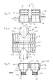
- a pipe connection part is generally designated by the reference number 10 and has a first half part 12 and a second half part 14 which are connected to one another via a film hinge 16.
- the (left) half part 12 has a central longitudinal axis 20, and the (right) half part 14 has a central longitudinal axis 22.
- a nozzle 24, 26 consists of two nozzle parts 24 and 26. This is followed by a part 28 of a stop part and a part 30 of the other stop part.
- Reference numerals 40, 42 denote the associated stop surfaces of stop part 28, 30, which are used for contacting a wall surrounding a hole, for example a housing.
- the connecting piece 24, 26 has an external thread 36, 38.
- the reference number 32 denotes a part of a section for receiving a corrugated tube
- the reference number 34 denotes the second part of the section for receiving a corrugated tube.
- two locking holes 44, 52 and a locking recess 48 are provided and - corresponding to this - in the right half part 14 two locking pins 46, 54 or a locking lug 50.
- FIG. 5 shows a further embodiment of a pipe connection part, designated overall by reference number 60, according to the present invention.
- a (left) half part 62 and a (right) half part 64 are connected to one another via a film hinge 66.
- the section 76, 78 designed to receive a corrugated pipe is followed by a connecting piece consisting of two connecting piece parts 68, 70, with which a stop part 72, 74 is formed in one piece.
- the nozzle part 68, 70 is provided with an internal thread 80, 82.
- the stop surface of the stop part 72, 74 is designated by the reference numerals 84, 86.
- the outer circumference of the stop part 72, 74 is designed as a hexagon in order to be able to attach an open-end wrench of a corresponding width.
- FIG. 6 shows a further exemplary embodiment of a pipe connection part, which is designated overall by reference number 90, in accordance with the present invention.
- the pipe connection part 90 is designed as a so-called T-piece.
- the two longitudinal axes 92, 94 of sections for receiving corrugated pipes coincide, and a transverse axis 96 extends transversely thereto at an angle of 90 °, the longitudinal axis of a connecting piece provided with an external thread.
- One section for receiving a corrugated pipe is designated by the reference numerals 98, 100 and the other section for receiving a corrugated pipe is designated by the reference numerals 102, 104.
- the reference numerals 98, 102 are designated by the reference numerals 98, 102 on the one hand and 100, 104 on the other hand.
- the nozzle in this embodiment consists of nozzle parts 104, 108, which are provided with an external thread 110, 112.
- the stop part in this embodiment is indicated by the stop surfaces 114, 116.
- the free inside diameter of the section for receiving the corrugated pipe or the sections for receiving the corrugated pipes and the free interior of the connecting piece are provided with essentially the same diameter.
- the corresponding inside diameters differ, so that a so-called reducer is formed.
- the reducing piece 120 shown in FIG. 7 has a (left) half part 122 and a (right) half part 124, which are integrally connected to one another via a film hinge 126.
- Reference numbers 128, 130 denote a nozzle part which has an internal thread 132, 134.
- a stop part 140, 142 is formed, the outer contour of which is shaped as a hexagon in order to be able to apply an open-end wrench there.
- the nozzle part 128, 130 merges gradually into a section 136, 138 for receiving a corrugated tube.
- the free inside diameter of the section 136, 138 for receiving a corrugated tube is reduced in diameter; the reducer 120 therefore serves to connect a corrugated tube with a reduced diameter compared to the other pipe connection parts.
- Figures 5 to 7 make the modular system diversity of the pipe connection parts according to the present invention clear.
- the pipe connection part 60 shown in FIG. 5 can be screwed onto the connecting piece 106, 108 of the T-piece 90 shown in FIG. 6 if the free inside diameter is to remain the same. If, on the other hand, the free inside diameter is to be reduced so that not so much space is required, and because only part of the cables or lines leading along the axes 94, 92 are to be branched off from the connecting piece 106, 108, then the connecting piece 106, 108 the reducer 120 shown in Figure 7 screwed.
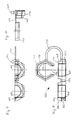
- FIGS. 8-10 show a divisible nut made of plastic, designated overall by reference numeral 150, in accordance with the present invention.
- the separable nut 150 has two half parts 152, 154 which are connected to one another via a film hinge 156.
- Each of the half parts 152, 154 has an internal thread 158 and 160, respectively.
- a locking recess 162 is provided on the (in FIG. 8 left) half part 152, and on the (right) half part 154 there is a corresponding locking lug 164 which corresponds to the locking recess 162.
- a certain weak point here is the relatively thin film hinge 156.
- the film hinge 156 is particularly stressed at higher actuation forces, i.e. when the nut 150 is strongly tightened, and this can result in the film hinge 156 stretching under excessive stress, as a result of which the nut 150 does not fit securely, for example, on the external thread of a connecting piece a pipe connector is more guaranteed, or even tears, making the nut 150 unusable would.
- a union nut 170 is used to overcome these difficulties.
- the two half parts 152, 154 each have a somewhat tapered section, which is provided with a specific outer contour 166 and 168, respectively.
- the outer contour 166 of the half part 152 can comprise three sides of a hexagon, and the other outer contour 168 of the other half part 154 also three (further) sides of a hexagon, so that the tapered section, when the nut 150 is closed, the outer contour 166, 168 of a hexagon Has.
- a corresponding inner contour 172 of the union nut 170 is adapted to this. However, this inner contour is not closed so that the union nut 170 can be pushed over, for example, cables that have already been laid, and therefore the union nut 170 is designed as an open ring which has an interruption point 176.
- the union nut 170 is first pushed on or clipped on.
- the union nut 170 therefore serves as a washer between a wall from which a socket protrudes through a hole and the nut 150. Then the nut 150 is closed and screwed onto the socket until it comes to rest loosely on the union nut 170.
- the inner contour 172 of the union nut 170 is provided with a chamfer 178, so that when the nut 150 is tightened further, the outer contour 166, 168 of the union nut 170, running onto the chamfer 178, turns into the inner contour 172 of the union nut 170. In this way, the nut 150 is prevented by the union nut 170 from expanding (for example by lengthening the film hinge 156).
- a connecting piece 174 connects the nut 150 to the union nut 170. In this way it is avoided that the union nut 170 can be lost, and an assembler becomes aware of the presence of the union nut 170 also always pointed out that this union nut 170 should be used.
- the nut 150, the connecting piece 174, and the union nut 170 can be produced in one piece in one work step, which also simplifies the manufacture and therefore reduces the cost.
- the connector 174 is designed so that it can - if necessary - easily be opened or disconnected; For this purpose, thinner points can be provided on the connecting piece 174 in the vicinity of the half part 154 and / or the union nut 170. In this way it can be achieved that - if necessary without having to use a tool - the connecting piece 174 can be disconnected or opened if it should interfere with the nut 150 when it is installed.
Landscapes
- Engineering & Computer Science (AREA)
- Architecture (AREA)
- Civil Engineering (AREA)
- Structural Engineering (AREA)
- Joints That Cut Off Fluids, And Hose Joints (AREA)
- Mutual Connection Of Rods And Tubes (AREA)
- Joints With Pressure Members (AREA)
- Holders For Apparel And Elements Relating To Apparel (AREA)
- Laying Of Electric Cables Or Lines Outside (AREA)
- Supports For Pipes And Cables (AREA)
- Lining Or Joining Of Plastics Or The Like (AREA)
- Rigid Pipes And Flexible Pipes (AREA)
- Branch Pipes, Bends, And The Like (AREA)
Applications Claiming Priority (2)
| Application Number | Priority Date | Filing Date | Title |
|---|---|---|---|
| DE4004564A DE4004564A1 (de) | 1990-02-14 | 1990-02-14 | Rohranschlussteil, rohrverbindungsteil, und zugehoerige mutter |
| DE4004564 | 1990-02-14 |
Publications (3)
| Publication Number | Publication Date |
|---|---|
| EP0442505A2 true EP0442505A2 (fr) | 1991-08-21 |
| EP0442505A3 EP0442505A3 (en) | 1992-10-21 |
| EP0442505B1 EP0442505B1 (fr) | 1995-01-11 |
Family
ID=6400140
Family Applications (1)
| Application Number | Title | Priority Date | Filing Date |
|---|---|---|---|
| EP91102113A Expired - Lifetime EP0442505B1 (fr) | 1990-02-14 | 1991-02-14 | Dispositif de jonction de tuyaux, dispositif de connexion de tuyaux et écrou accessoire |
Country Status (6)
| Country | Link |
|---|---|
| US (1) | US5277459A (fr) |
| EP (1) | EP0442505B1 (fr) |
| JP (1) | JPH0742889A (fr) |
| AT (1) | ATE117135T1 (fr) |
| DE (2) | DE4004564A1 (fr) |
| ES (1) | ES2069106T3 (fr) |
Cited By (8)
| Publication number | Priority date | Publication date | Assignee | Title |
|---|---|---|---|---|
| DE4300521A1 (de) * | 1993-01-12 | 1994-07-14 | Weidmueller Interface | Kabelabdichtungs- und Zugentlastungsvorrichtung für Wanddurchbrüche |
| EP0735394A3 (fr) * | 1995-03-30 | 1997-08-06 | Plessey Telecomm | Dispositif de serrage à fibre optique |
| US6211465B1 (en) | 1997-04-16 | 2001-04-03 | Sofanou S.A. | Sealed connecting box for fitting a tube to an aperture of a wall |
| EP2495484A1 (fr) | 2011-03-01 | 2012-09-05 | Fränkische Industrial Pipes GmbH & Co. KG | Dispositif de liaison de conduits et agencement de jonction de conduites |
| EP2339217A4 (fr) * | 2008-10-21 | 2013-04-17 | Makita Corp | Tuyau doté d un cordon et collecteur de poussière |
| EP2775178A1 (fr) * | 2013-03-07 | 2014-09-10 | Gemü Gebr. Müller Apparatebau Gmbh & Co. Kommanditgesellschaf | Bloc distributeur |
| DE102013220564A1 (de) * | 2013-10-11 | 2015-04-16 | Schlemmer Gmbh | Verteiler aus Kunststoff für Wellschlauchleitungen |
| FR3023991A1 (fr) * | 2014-07-16 | 2016-01-22 | Leoni Wiring Systems France | Boitier de liaison entre un cable electrique et un connecteur |
Families Citing this family (40)
| Publication number | Priority date | Publication date | Assignee | Title |
|---|---|---|---|---|
| DE4206016C2 (de) * | 1992-02-27 | 1994-02-10 | Deutsche Aerospace Airbus | Anschlußelement zur Halterung eines Schutzschlauches |
| DE4206014C2 (de) * | 1992-02-27 | 1994-02-10 | Deutsche Aerospace Airbus | Anschlußelement zur Haltung eines Schutzschlauches |
| DE4236838A1 (de) * | 1992-10-31 | 1994-05-05 | Heidelberger Druckmasch Ag | Einrichtung zum Schutz von Leitungen |
| DE4424804C1 (de) * | 1994-07-14 | 1995-08-24 | Daimler Benz Ag | Leitungsanordnung, insbesondere von elektrischen oder pneumatischen Leitungen in einem Kraftfahrzeug |
| FR2738084B1 (fr) * | 1995-08-25 | 1997-11-07 | Campion Jean Luc | Raccord pour la mise en continuite de deux conduites pour cables telephoniques |
| DE19537479C2 (de) * | 1995-10-09 | 2001-12-20 | Ct Therm Abgastechnik Gmbh | Geschlitzte Hülse |
| DE19608118A1 (de) * | 1996-03-02 | 1997-09-04 | Abb Patent Gmbh | Abdichtung |
| US5984375A (en) * | 1997-07-23 | 1999-11-16 | Schlumberger Industries, Inc. | Hose collar and method of use therefor |
| DE19911724C1 (de) * | 1999-03-16 | 2000-10-26 | Pma Ag Uster | Wellrohrverbindung mit Sperrabschnitt |
| DE29909715U1 (de) | 1999-06-04 | 1999-09-02 | Anton Hummel Verwaltungs Gmbh, 79183 Waldkirch | Wellschlauch mit einer Halterung |
| DE19943764C5 (de) * | 1999-09-13 | 2004-07-29 | Schlemmer Gmbh | Anschlußvorrichtung für eine Wellschlauchleitung und Leitungssystem |
| US6302446B1 (en) * | 2000-01-24 | 2001-10-16 | Spears Manufacturing Co. | Union fitting replacement nut |
| US7438326B1 (en) * | 2000-08-31 | 2008-10-21 | Tuf-Tite, Inc. | Tee baffle for use at inlet or outlet of septic and other on-site waste disposal systems |
| SE524585C2 (sv) * | 2002-03-04 | 2004-08-31 | Aba Sweden Ab | Kopplingsanordning för rör innefattande två ledbara halvor |
| US20050269124A1 (en) * | 2002-07-03 | 2005-12-08 | Shigeru Suzuki | Slidingly detachable core member and cold shrink tube unit having the same |
| US6811191B2 (en) * | 2002-10-01 | 2004-11-02 | Mark S. Mills | Coupling assembly for connecting corrugated conduit |
| FR2847963B1 (fr) * | 2002-11-29 | 2007-02-02 | Sarl Francois Inglese | Dispositif de connexion de canalisations flexibles |
| FR2847964B1 (fr) * | 2002-11-29 | 2008-07-11 | Sarl Francois Inglese | Dispositif de connexion de canalisations flexibles |
| US7388149B2 (en) * | 2004-05-03 | 2008-06-17 | Creative Bath Products, Inc. | Coupling for corrugated cable conduits for enclosing cables |
| CN101002046A (zh) * | 2004-10-07 | 2007-07-18 | 卢克摩擦片和离合器两合公司 | 用于将管道连接在系统上的连接装置 |
| US8540471B2 (en) * | 2006-07-05 | 2013-09-24 | Visenut Llc | Quick attaching and detaching nut |
| US20080080957A1 (en) * | 2006-10-02 | 2008-04-03 | James Dan L | Sliding nut with captive screw |
| US7661915B2 (en) * | 2006-10-02 | 2010-02-16 | Whipple Charles E | Trapeze hanger |
| JPWO2010089894A1 (ja) * | 2009-02-09 | 2012-08-09 | イイファス株式会社 | 差込ワッシャー |
| CA2755945A1 (fr) * | 2009-03-20 | 2010-09-23 | Drexan Energy Systems Inc. | Appareil de terminaison de cables et procedes afferents |
| AU2010292369B9 (en) * | 2009-09-11 | 2015-03-19 | Victaulic Company | Flexible assembly for sprinklers |
| CN201787250U (zh) * | 2010-08-04 | 2011-04-06 | 上海盈达空调设备有限公司 | 用于空调通风管的组合结构 |
| US8967676B1 (en) * | 2013-02-01 | 2015-03-03 | Lane Enterprises, Inc. | Two-piece split coupler for coupling large-diameter plastic corrugated pipe |
| US8746746B1 (en) * | 2013-02-28 | 2014-06-10 | Charlie J. Schafer | Nestable connector |
| ITRM20130479A1 (it) * | 2013-08-22 | 2015-02-23 | Andrea Dipanati | Kit di elementi di collegamento meccanici filettati apribili reversibilmente con relativi accessori. |
| WO2015153416A1 (fr) * | 2014-03-31 | 2015-10-08 | Novelis Inc. | Douille de protection de bords dotée d'un collier intégré |
| US10648601B2 (en) | 2014-06-10 | 2020-05-12 | Kohler Co. | Quick connect system for a fluid coupling |
| US9926900B2 (en) * | 2015-01-15 | 2018-03-27 | GM Global Technology Operations LLC | Fluid spray shield and secondary retention clip for a quick connector joint |
| US10113669B2 (en) * | 2016-01-15 | 2018-10-30 | The Boeing Company | Pass-through bulkhead seal fitting |
| US10502353B2 (en) | 2016-05-27 | 2019-12-10 | Kohler Co. | Quick connect release system for a fluid coupling |
| JP6708681B2 (ja) * | 2018-03-12 | 2020-06-10 | トヨタ自動車株式会社 | プロテクタ |
| WO2020154946A1 (fr) * | 2019-01-30 | 2020-08-06 | Vincent Medical (Dongguan) Technology Co., Ltd. | Tuyau flexible à manchon pouvant être fermé, procédé de fabrication de celui-ci, et dispositifs le contenant |
| DE102019214811A1 (de) * | 2019-09-26 | 2021-04-01 | Zf Friedrichshafen Ag | Wellrohrverbinder |
| US12188600B2 (en) * | 2023-03-28 | 2025-01-07 | Advanced Drainage Systems, Inc. | Fasteners for a manifold |
| US20250146601A1 (en) * | 2023-11-07 | 2025-05-08 | Icon Containment Solutions, Llc | Snap lock fitting |
Family Cites Families (24)
| Publication number | Priority date | Publication date | Assignee | Title |
|---|---|---|---|---|
| DE7315704U (de) * | 1973-08-16 | Patzner Kg | Aus Kunststoff gespritzter Gewinde stopfen | |
| FR907211A (fr) * | 1944-09-28 | 1946-03-06 | écrou rapide de sécurité | |
| US2664023A (en) * | 1951-11-30 | 1953-12-29 | Mugford Ronald | Snap-on split nut |
| US3041088A (en) * | 1959-06-18 | 1962-06-26 | Jr Ira M Brandon | Coupling assembly |
| FR1536344A (fr) * | 1967-07-03 | 1968-08-10 | Nouvel écrou à pose rapide | |
| US3711632A (en) * | 1971-12-02 | 1973-01-16 | Gen Motors Corp | End fitting for corrugated conduit |
| US3711633A (en) * | 1971-12-02 | 1973-01-16 | Gen Motors Corp | Fitting means for axially slit corrugated conduits |
| NL7507218A (en) * | 1975-06-17 | 1976-12-21 | Wavin Bv | Connector for corrugated plastic tubes - has two half-shells hinged at one side and with locking means at other, and tube retaining means |
| DE2553255A1 (de) * | 1975-11-27 | 1977-10-27 | Fresch Schrauben Handels Gmbh | In achsialrichtung in zwei haelften geteilte schraubenmutter |
| US4248459A (en) * | 1978-02-06 | 1981-02-03 | Indian Head Inc. | Flexible conduit system |
| JPS5825508B2 (ja) * | 1979-01-23 | 1983-05-27 | 美好 武藤 | 選果機 |
| US4274323A (en) * | 1979-05-08 | 1981-06-23 | Herbert Resnicow | Shaft-mounted assembly |
| US4443031A (en) * | 1982-11-04 | 1984-04-17 | Thyssen-Bornemisza Inc. | Connector fitting for connecting corrugated conduit sections |
| US4616105A (en) * | 1984-10-26 | 1986-10-07 | Tbg Inc. | Adapter fitting for connecting flexible conduit to electrical outlet boxes |
| GB2197409B (en) * | 1986-10-31 | 1990-08-22 | Kitz Corp | Pipe joint |
| DE3640226A1 (de) * | 1986-11-25 | 1988-06-01 | Kirchner Fraenk Rohr | Kunststoff-schutzrohranordnung fuer leitungen |
| JP2557399B2 (ja) * | 1987-04-28 | 1996-11-27 | 北川工業株式会社 | 波形管接続具 |
| JPH0510498Y2 (fr) * | 1987-04-28 | 1993-03-15 | ||
| US4795197A (en) * | 1987-06-29 | 1989-01-03 | Deere & Company | Coupling for seed and fertilizer hoses |
| DE3721354A1 (de) * | 1987-06-29 | 1989-01-12 | Pma Elektro Ag | Anschlussarmatur fuer flexible wellschlaeuche |
| US4829145A (en) * | 1987-10-01 | 1989-05-09 | Queen City Plastics, Inc. | Corrugated plastic conduit system |
| DE3739745C1 (en) * | 1987-11-24 | 1988-11-24 | Helmut Schuchardt | Connecting and joining sleeve for flexible tubes |
| US4888453A (en) * | 1988-10-20 | 1989-12-19 | General Motors Corporation | Panel mounted breakout fitting |
| FR2642814B1 (fr) * | 1989-02-08 | 1991-05-10 | Labinal | Bague de fermeture de gaines annelees |
-
1990
- 1990-02-14 DE DE4004564A patent/DE4004564A1/de active Granted
-
1991
- 1991-02-13 JP JP3041212A patent/JPH0742889A/ja active Pending
- 1991-02-14 AT AT91102113T patent/ATE117135T1/de not_active IP Right Cessation
- 1991-02-14 EP EP91102113A patent/EP0442505B1/fr not_active Expired - Lifetime
- 1991-02-14 ES ES91102113T patent/ES2069106T3/es not_active Expired - Lifetime
- 1991-02-14 US US07/655,496 patent/US5277459A/en not_active Expired - Fee Related
- 1991-02-14 DE DE59104182T patent/DE59104182D1/de not_active Expired - Fee Related
Cited By (11)
| Publication number | Priority date | Publication date | Assignee | Title |
|---|---|---|---|---|
| DE4300521A1 (de) * | 1993-01-12 | 1994-07-14 | Weidmueller Interface | Kabelabdichtungs- und Zugentlastungsvorrichtung für Wanddurchbrüche |
| EP0735394A3 (fr) * | 1995-03-30 | 1997-08-06 | Plessey Telecomm | Dispositif de serrage à fibre optique |
| US6211465B1 (en) | 1997-04-16 | 2001-04-03 | Sofanou S.A. | Sealed connecting box for fitting a tube to an aperture of a wall |
| EP2339217A4 (fr) * | 2008-10-21 | 2013-04-17 | Makita Corp | Tuyau doté d un cordon et collecteur de poussière |
| US8650706B2 (en) | 2008-10-21 | 2014-02-18 | Makita Corporation | Corded hose and dust collector |
| EP2495484A1 (fr) | 2011-03-01 | 2012-09-05 | Fränkische Industrial Pipes GmbH & Co. KG | Dispositif de liaison de conduits et agencement de jonction de conduites |
| DE102011004925A1 (de) | 2011-03-01 | 2012-09-06 | Fränkische Industrial Pipes GmbH & Co. KG | Rohrverbindungsvorrichtung und Rohrverbindungsanordnung |
| EP2775178A1 (fr) * | 2013-03-07 | 2014-09-10 | Gemü Gebr. Müller Apparatebau Gmbh & Co. Kommanditgesellschaf | Bloc distributeur |
| DE102013220564A1 (de) * | 2013-10-11 | 2015-04-16 | Schlemmer Gmbh | Verteiler aus Kunststoff für Wellschlauchleitungen |
| DE102013220564B4 (de) * | 2013-10-11 | 2019-08-29 | Schlemmer Gmbh | Verteiler aus Kunststoff für Wellschlauchleitungen |
| FR3023991A1 (fr) * | 2014-07-16 | 2016-01-22 | Leoni Wiring Systems France | Boitier de liaison entre un cable electrique et un connecteur |
Also Published As
| Publication number | Publication date |
|---|---|
| DE4004564C2 (fr) | 1993-09-02 |
| JPH0742889A (ja) | 1995-02-10 |
| DE59104182D1 (de) | 1995-02-23 |
| EP0442505B1 (fr) | 1995-01-11 |
| DE4004564A1 (de) | 1991-08-29 |
| EP0442505A3 (en) | 1992-10-21 |
| ATE117135T1 (de) | 1995-01-15 |
| ES2069106T3 (es) | 1995-05-01 |
| US5277459A (en) | 1994-01-11 |
Similar Documents
| Publication | Publication Date | Title |
|---|---|---|
| EP0442505B1 (fr) | Dispositif de jonction de tuyaux, dispositif de connexion de tuyaux et écrou accessoire | |
| EP1845299B1 (fr) | Dispositif de raccordement pour un tuyau | |
| EP0268869B1 (fr) | Dispositif à tuyau protecteur en matériau synthétique pour conduites | |
| DE2828893C2 (de) | Rohrverbinder für Kabelschutzrohre | |
| DE19615442C2 (de) | Steckschnellkupplungs-Vorrichtung | |
| EP2240987B1 (fr) | Dispositif a enfichage | |
| DE3101558A1 (de) | Vorrichtung zum halten von kabeln, leitungen, schlaeuchen oder dergleichen gegenstaende | |
| DE3590081T1 (de) | Kabelstecker mit integrierter Zugentlastung | |
| DE69420121T2 (de) | Durch einen Bolzen festgeklemmte Kupplung | |
| DE3734548A1 (de) | Anschlussverbindungsstueck | |
| DE102018127230A1 (de) | Wanddurchführungseinrichtung | |
| DE60119577T2 (de) | Schnellkupplung mit drehverrieglung für hochdruck | |
| WO2022135917A1 (fr) | Bouchon destiné à être fixé sur des conduites et d'autres éléments allongés | |
| DE19526868C2 (de) | Sicherungselement für mehrteilige Verbindungseinheiten wie Schraubverbindungen und dergleichen | |
| EP3583664A1 (fr) | Protection contre le pliage de câbles préfabriqués | |
| DE202017006800U1 (de) | Innenliegende Zugentlastung für einen Steckverbinder | |
| DE102009048481B4 (de) | Elektrischer Steckverbinder | |
| EP0579125A1 (fr) | Raccord à vis en matière plastique pour entrée et traversée de paroi, étanchéité et décharge de traction de câbles, conduits ou tuyaux souples | |
| DE3439629C2 (de) | Zugentlastung für die elektrische Leitung eines Steckers oder einer Buchse | |
| DE102018131310A1 (de) | Adaptergehäuse für einen Kontakteinsatz zur Fixierung auf einer Hutschiene | |
| DE2316747A1 (de) | Zugentlastungsklemme fuer elektrische leitungen | |
| DE3116027A1 (de) | Elektrischer steckverbinder | |
| DE3937888A1 (de) | Rohrverbindung | |
| DE3708480A1 (de) | Gelenkverbindung fuer rohre | |
| DE10357646B4 (de) | Wanddurchführung |
Legal Events
| Date | Code | Title | Description |
|---|---|---|---|
| PUAI | Public reference made under article 153(3) epc to a published international application that has entered the european phase |
Free format text: ORIGINAL CODE: 0009012 |
|
| 17P | Request for examination filed |
Effective date: 19910227 |
|
| AK | Designated contracting states |
Kind code of ref document: A2 Designated state(s): AT BE CH DE ES FR GB IT LI LU NL SE |
|
| PUAL | Search report despatched |
Free format text: ORIGINAL CODE: 0009013 |
|
| AK | Designated contracting states |
Kind code of ref document: A3 Designated state(s): AT BE CH DE ES FR GB IT LI LU NL SE |
|
| 17Q | First examination report despatched |
Effective date: 19931116 |
|
| GRAA | (expected) grant |
Free format text: ORIGINAL CODE: 0009210 |
|
| AK | Designated contracting states |
Kind code of ref document: B1 Designated state(s): AT BE CH DE ES FR GB IT LI LU NL SE |
|
| REF | Corresponds to: |
Ref document number: 117135 Country of ref document: AT Date of ref document: 19950115 Kind code of ref document: T |
|
| ITF | It: translation for a ep patent filed | ||
| REF | Corresponds to: |
Ref document number: 59104182 Country of ref document: DE Date of ref document: 19950223 |
|
| ET | Fr: translation filed | ||
| REG | Reference to a national code |
Ref country code: ES Ref legal event code: FG2A Ref document number: 2069106 Country of ref document: ES Kind code of ref document: T3 |
|
| GBT | Gb: translation of ep patent filed (gb section 77(6)(a)/1977) |
Effective date: 19950404 |
|
| PLBE | No opposition filed within time limit |
Free format text: ORIGINAL CODE: 0009261 |
|
| STAA | Information on the status of an ep patent application or granted ep patent |
Free format text: STATUS: NO OPPOSITION FILED WITHIN TIME LIMIT |
|
| 26N | No opposition filed | ||
| REG | Reference to a national code |
Ref country code: GB Ref legal event code: IF02 |
|
| PGFP | Annual fee paid to national office [announced via postgrant information from national office to epo] |
Ref country code: GB Payment date: 20020124 Year of fee payment: 12 |
|
| PGFP | Annual fee paid to national office [announced via postgrant information from national office to epo] |
Ref country code: CH Payment date: 20020128 Year of fee payment: 12 |
|
| PGFP | Annual fee paid to national office [announced via postgrant information from national office to epo] |
Ref country code: NL Payment date: 20020129 Year of fee payment: 12 Ref country code: AT Payment date: 20020129 Year of fee payment: 12 |
|
| PGFP | Annual fee paid to national office [announced via postgrant information from national office to epo] |
Ref country code: FR Payment date: 20020201 Year of fee payment: 12 |
|
| PGFP | Annual fee paid to national office [announced via postgrant information from national office to epo] |
Ref country code: SE Payment date: 20020204 Year of fee payment: 12 |
|
| PGFP | Annual fee paid to national office [announced via postgrant information from national office to epo] |
Ref country code: DE Payment date: 20020207 Year of fee payment: 12 |
|
| PGFP | Annual fee paid to national office [announced via postgrant information from national office to epo] |
Ref country code: LU Payment date: 20020213 Year of fee payment: 12 |
|
| PGFP | Annual fee paid to national office [announced via postgrant information from national office to epo] |
Ref country code: ES Payment date: 20020214 Year of fee payment: 12 |
|
| PGFP | Annual fee paid to national office [announced via postgrant information from national office to epo] |
Ref country code: BE Payment date: 20020220 Year of fee payment: 12 |
|
| PG25 | Lapsed in a contracting state [announced via postgrant information from national office to epo] |
Ref country code: LU Free format text: LAPSE BECAUSE OF NON-PAYMENT OF DUE FEES Effective date: 20030214 Ref country code: GB Free format text: LAPSE BECAUSE OF NON-PAYMENT OF DUE FEES Effective date: 20030214 Ref country code: AT Free format text: LAPSE BECAUSE OF NON-PAYMENT OF DUE FEES Effective date: 20030214 |
|
| PG25 | Lapsed in a contracting state [announced via postgrant information from national office to epo] |
Ref country code: SE Free format text: LAPSE BECAUSE OF NON-PAYMENT OF DUE FEES Effective date: 20030215 Ref country code: ES Free format text: LAPSE BECAUSE OF NON-PAYMENT OF DUE FEES Effective date: 20030215 |
|
| PG25 | Lapsed in a contracting state [announced via postgrant information from national office to epo] |
Ref country code: LI Free format text: LAPSE BECAUSE OF NON-PAYMENT OF DUE FEES Effective date: 20030228 Ref country code: CH Free format text: LAPSE BECAUSE OF NON-PAYMENT OF DUE FEES Effective date: 20030228 Ref country code: BE Free format text: LAPSE BECAUSE OF NON-PAYMENT OF DUE FEES Effective date: 20030228 |
|
| PG25 | Lapsed in a contracting state [announced via postgrant information from national office to epo] |
Ref country code: NL Free format text: LAPSE BECAUSE OF NON-PAYMENT OF DUE FEES Effective date: 20030901 |
|
| PG25 | Lapsed in a contracting state [announced via postgrant information from national office to epo] |
Ref country code: DE Free format text: LAPSE BECAUSE OF NON-PAYMENT OF DUE FEES Effective date: 20030902 |
|
| EUG | Se: european patent has lapsed | ||
| GBPC | Gb: european patent ceased through non-payment of renewal fee | ||
| REG | Reference to a national code |
Ref country code: CH Ref legal event code: PL |
|
| PG25 | Lapsed in a contracting state [announced via postgrant information from national office to epo] |
Ref country code: FR Free format text: LAPSE BECAUSE OF NON-PAYMENT OF DUE FEES Effective date: 20031031 |
|
| NLV4 | Nl: lapsed or anulled due to non-payment of the annual fee |
Effective date: 20030901 |
|
| REG | Reference to a national code |
Ref country code: FR Ref legal event code: ST |
|
| REG | Reference to a national code |
Ref country code: ES Ref legal event code: FD2A Effective date: 20030215 |
|
| PG25 | Lapsed in a contracting state [announced via postgrant information from national office to epo] |
Ref country code: IT Free format text: LAPSE BECAUSE OF NON-PAYMENT OF DUE FEES Effective date: 20050214 |