EP0442534B1 - Reinigungsvorrichtung für ein Bilderzeugungsgerät - Google Patents
Reinigungsvorrichtung für ein Bilderzeugungsgerät Download PDFInfo
- Publication number
- EP0442534B1 EP0442534B1 EP91104153A EP91104153A EP0442534B1 EP 0442534 B1 EP0442534 B1 EP 0442534B1 EP 91104153 A EP91104153 A EP 91104153A EP 91104153 A EP91104153 A EP 91104153A EP 0442534 B1 EP0442534 B1 EP 0442534B1
- Authority
- EP
- European Patent Office
- Prior art keywords
- recovery box
- toner
- toner recovery
- box
- actuating element
- Prior art date
- Legal status (The legal status is an assumption and is not a legal conclusion. Google has not performed a legal analysis and makes no representation as to the accuracy of the status listed.)
- Expired - Lifetime
Links
- 238000004140 cleaning Methods 0.000 title claims description 29
- 238000011084 recovery Methods 0.000 claims description 76
- 239000000463 material Substances 0.000 description 9
- 230000000994 depressogenic effect Effects 0.000 description 6
- 230000002093 peripheral effect Effects 0.000 description 2
- 238000004062 sedimentation Methods 0.000 description 2
- 238000005549 size reduction Methods 0.000 description 2
- 239000002699 waste material Substances 0.000 description 2
- 230000015572 biosynthetic process Effects 0.000 description 1
- 230000007423 decrease Effects 0.000 description 1
- 230000001419 dependent effect Effects 0.000 description 1
- 238000000034 method Methods 0.000 description 1
- 238000012986 modification Methods 0.000 description 1
- 230000004048 modification Effects 0.000 description 1
- 230000000452 restraining effect Effects 0.000 description 1
- 238000007789 sealing Methods 0.000 description 1
- 229920003002 synthetic resin Polymers 0.000 description 1
- 239000000057 synthetic resin Substances 0.000 description 1
Images


Classifications
-
- G—PHYSICS
- G03—PHOTOGRAPHY; CINEMATOGRAPHY; ANALOGOUS TECHNIQUES USING WAVES OTHER THAN OPTICAL WAVES; ELECTROGRAPHY; HOLOGRAPHY
- G03G—ELECTROGRAPHY; ELECTROPHOTOGRAPHY; MAGNETOGRAPHY
- G03G21/00—Arrangements not provided for by groups G03G13/00 - G03G19/00, e.g. cleaning, elimination of residual charge
- G03G21/10—Collecting or recycling waste developer
- G03G21/12—Toner waste containers
Definitions
- the invention relates to a cleaning device for an image-forming machine according to the preamble of claim 1.
- a cleaning device for an image-forming machine according to the preamble of claim 1.
- Such a device is known from JP-58-179886.
- Such a cleaning device removes residual toner from the surface of a photosensitive material in an image-forming machine such as an electrostatic copying machine.
- a latent electrostatic image is formed on the surface of a photosensitive material disposed on a rotating drum or an endless belt and then developed to a toner image. Then, the toner image is transferred to a receptor sheet such as ordinary paper, and for the next cycle of image formation, the toner image remaining on the surface of the photosensitive material is then removed.
- the cleaning device used to remove the residual toner from the surface of the photosensitive material should be provided with toner holding means for holding the removed toner as well as means for removing the residual toner from the surface of the photosensitive material.
- the size reduction of the image-forming machine desirably requires the size reduction of the toner holding means in the cleaning device.
- the toner holding capacity naturally decreases.
- it has already been proposed to construct a detachable toner recovery box as the toner holding means, and to replace it with a new toner recovery box when it is filled up with the toner, and such toner holding means has already come into commercial use.
- the cleaning device provided in a small-sized and low-priced image-forming machine, it is desired to omit a relatively complex and expensive helical vane mechanism and the like for forwardly or rearwardly transferring the toner removed from the photosensitive member. It is important in this case to use a toner recovery box of a type having a toner inlet extending in the front-rear direction along the photosensitive material in order to recover the toner sufficiently uniformly throughout the toner recovery box. When a toner recovery box of such a type is used, the toner frequently scatters from the toner inlet, and contaminates the surrounding environment or the operator's hands and garment, etc., during or after the toner recovery box filled with the toner is removed from the cleaning device.
- JP-58-179886 describes a processing vessel of waste toner.
- the vessel ist stored freely attachably and detachably in a cleaning device provided with a cleaning blade.
- a scooping member is turned around a pin. The toner scraped off by the blade is dropped and stored in the vessel through an aperture of the vessel.
- the scooping member is turned counterclockwise to close the aperture. Consequently, the vessel is attached to or detached from the cleaning device in the closed state.
- JP-60-26377 discloses a developing device of a copying machine.
- two covers are joint together with a spring to close the toner discharge port.
- a pin provided to the main frame side is inserted into a notch part provided to the covers, which are then turned upward and downward around a shaft as a fulcrum against the elastic force of the spring.
- the toner discharge port is opened.
- the toner recovery box is inserted into the receiving space by being moved at least rearwardly and withdrawn from the receiving space by being moved at least forwardly; and the actuating element and the non-actuating element are constructed such that while the toner recovery box is moved rearwardly to a particular position, the actuating element does not act on the non-actuating element, but while the toner recovery box is moved rearwardly from the particular position to a final position, the actuating element acts on the non-actuating element.
- the toner inlet of the toner recovery box is surrounded all along with the supporting frame structure.
- at least the front surface of the receiving space is open.
- the actuating element acts on the non-actuating element to bring the cover member to the open position and to expose the toner inlet of the box. Hence toner is transferred from the toner inlet to the inside of the box without any trouble.
- the actuating element fails to act on the non-actuating element.
- the cover member is brought to the closed position by the biasing action of the elastic means, and the toner inlet of the box is closed. Accordingly, scattering of the toner from the toner inlet is exactly prevented.
- Figure 1 is a sectional view showing a unit including an embodiment of the cleaning device constructed in accordance with this invention.
- Figure 2 is a side elevation showing a toner recovery box receiving space in the unit of Figure 1.
- Figure 3 is a partial perspective view showing the toner recovery box receiving space in the unit of Figure 1 as it is viewed along the line IX-IX of Figure 2.
- Figure 4 is an exploded partial perspective view showing the front end portion of the toner recovery box receiving space in the unit of Figure 1.
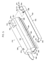
- Figure 5 is an exploded perspective view showing a toner recovery box in the unit of Figure 1.
- Figures 6 -A, 6 -B and 6 -C are respectively a side, a front and a sectional view which show the toner recovery box in the unit of Figure 1 as it has been inserted into the toner recovery box receiving space to a particular position.
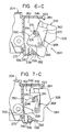
- Figures 7 -A, 7 -B and 7 -C are a side, a front and a sectional view which respectively show the toner recovery box in the unit of Figure 1 as it has been inserted into the toner recovery box receiving space to a final position.
- FIG. 1 illustrates a unit containing an embodiment of the cleaning device constructed in accordance with this invention.
- the unit shown generally at 202 has a supporting frame structure 204 on which are mounted a cleaning device shown generally at 212 together with a rotating drum 206 and a charging corona discharger 208.
- the cleaning device 212 comprises removing means 214, sealing means 216, carry-in means 218 and toner holding means 220.
- a toner recovery box receiving space 262 extending in the front-rear direction (the direction perpendicular to the sheet surface in Figure 1) is formed in the left side portion in Figure 1 of the supporting frame structure 204 of the unit 202.
- a toner recovery box shown generally at 264 which constitutes the toner holding means 220 is detachably inserted in the space 262.
- the space 262 formed in the supporting structure 204 is opened entirely in its front surface, nearly entirely in its left side surface and the left half portion of its under surface.
- the supporting frame structure 204 has a bottom wall 266 extending substantially horizontally along the right half portion of the under surface of the space 262, an upper wall 268 extending substantially horizontally along the upper surface of the space 262, and a rear wall 270 extending substantially vertically from the rear end of the bottom wall 266 to the rear end of the upper wall 268.
- An abutting stepped portion 274 extending in the front-rear direction is formed in one side surface of the upper portion of the guide wall 272, and furthermore, guide walls 276 and 278 projecting upwardly are formed in the bottom wall 266 in spaced-apart relationship, and define a guide channel 280 extending in the front-rear direction.
- a lower part guiding longitudinal protrusion 282 projecting to the left in Figure 1 is formed in the guide wall 278.
- the lower part guiding longitudinal protrusion 282 extends substantially horizontally in the rearward direction from its front end kept in alignment with the front end of the bottom wall 266, but does not extend to the rear wall 270 and terminates at a point apart from the rear wall 270 by a predetermined distance.
- An upper part guiding longitudinal protrusion 284 extending substantially vertically from the left side edge is formed in the upper wall 268.
- the upper part guiding protrusion 284 extends from its front end kept in alignment with the front end of the upper wall 268 to the rear wall 270 and has rectangular notches 286 and 288 formed respectively at its front end portion and rear end portion.
- a projecting portion 290 extending downwardly is formed at the rear end of the upper part guiding longitudinal protrusion 284.
- a continuously extending opening 292 is formed in the rear end portion of the upper wall 268 and the upper portion of the rear wall 270. Furthermore, as will be stated hereinafter, when the unit 202 is mounted in the housing of the image-forming machine, a toner detector 240 fixed to the under surface of the base plate 231 of the housing projects into the space 262 through the opening 292. As shown in Figures 2 and 3, an actuating element 294 constructed of a forwardly extending projecting piece is formed in the front surface of the rear wall 270. Furthermore, in the lower end of the rear wall 270 is formed a forwardly extending L-shaped projecting wall portion 296, and a stopping block portion 298 is formed at a corner in the rear end of the projecting wall portion 296.
- an additional member 300 is fixed to the front surface of the supporting frame structure 204 by a set screw (not shown), and the supporting frame structure 204 projects forwardly at its site where the space 262 exists. If desired, the additional member 300 may be formed integrally with the supporting frame structure 204.
- the additional member 300 has a bottom wall 302, a relatively high side wall 304 extending upwardly from one side edge of the bottom wall 302 and a relatively low side wall 306 extending upwardly from the othe rside edge of the bottom wall 302.
- a guide wall 308 is formed in the bottom wall 302, and the guide wall 308 and the lower portion of the side wall 304 define a guide channel 310 which extends in the front-rear direction in alignment with the guide channel 280.
- the inside surface of the side wall 304 has an arcuate portion 312 and a flat portion 314 extending upwardly from the arcuate portion 312. It will be seen by referring to Figure 6 -B in conjunction with Figure 4 that the arcuate portion 312 and the flat portion 314 in the inside surface of the side wall 304 are of nearly the same shape as an arcuate portion 318 and a flat portion 320 formed in one side edge of the front wall 316 of the supporting frame 204, but are displaced counterclockwise in Figure 6 -B by a predetermined angle with respect to the arcuate portion 318 and the flat portion 320.
- a dent portion 322 dented clockwise in Figure 6- B is formed in the rear part of the inside surface of the side wall 304.
- the dent portion 322 has an arcuate portion 324 and a flat portion 326 which are in alignment with the arcuate portion 318 and the flat portion 320, or in other words, form the same plane as the arcuate portion 318 and the flat portion 320.
- the toner recovery box shown generally at 264 includes a box 328 preferably formed of transparent or semi-transparent synthetic resin.
- the box 328 is a hollow body extending in an elongate shape in the front-rear direction.
- One side surface i.e. the right side surface in Figure 1
- a toner inlet 334 preferably a rectangular opening extending in the front-rear direction over nearly the entire length of the box 328 is formed in the lower part of the arcuate portion 330.
- a downwardly extending guided protrusion 336 is formed in the under surface of the box 328.
- the lower end portion of the guided protrusion 336 extending in the front-rear direction has a nearly circular sectional shape.
- a rectangular lower part guided protrusion 338 projecting to the right in Figure 1.
- Upwardly projecting rectangular upper part guided protrusions 340 and 342 are formed at the front end portion and the rear end portion of the upper surface of the box 328.
- a nearly rectangular sedimentation portion 344 exists on one side of the rear end portion of the upper surface of the box 328, and a projecting portion 346 to be detected is formed in the sedimentation 344.
- a forwardly projecting gripping piece 348 is formed in the front surface of the box 328.
- the toner recovery box 264 further includes a cover member 350 having a main portion 352 being arcuate in section and extending in the front-rear direction. As shown in Figure 1, a long protrusion 354 extending inwardly is formed in the lower end edge of the main portion 352. Linking pieces 356 and 358 extending inwardly are formed respectively at the front end and the rear end of the main portion 352. Holes 357 and 359 are respectively provided in the linking pieces 356 and 358. Depressed portions 360 and 362 corresponding to the linking pieces 356 and 358 are formed in the front surface and the rear surface of the box 328.
- a forwardly projecting short shaft 364 is provided in the depressed portion 360, and a rearwardly projecting short shaft 366 (Figure 6 -C), in the depressed portion 362.
- the cover member 350 is mounted on the box 328 by positioning the linking piece 356 at the depressed portion 360, and inserting the short shaft 364 into the hole 357, and also positioning the linking piece 358 at the depressed portion 362 and inserting the short shaft 366 ( Figure 6 -C) into the hole 359.
- the cover member 350 so mounted on the box 328 is free to pivot between a closed position (the position shown in Figures 6 -B and 6 -C) at which the under surface of its long protrusion 354 (Figure 1), abuts against the lower edge of the toner inlet 334 and a position (the position shown in Figures 1, 7 -B and 7 -C) at which the upper surface of the long protrusion 354 ( Figure 1) abuts against the upper edge of the toner inlet 334 about an axis extending in the front-rear direction, i.e. the central axis of the short shafts 364 and 366, as a center.
- Elastic means 368 constructed of a helical spring is disposed between the box 328 and the cover member 350.
- the elastic means 368 elastically biases the cover member 350 clockwise (counterclockwise in Figure 6 -C) as viewed from the front side of the cover member 350 and holds it elastically at the above closed position.
- the cover member 350 is held at the closed position, the toner inlet 334 of the box 328 is closed by the cover member 350.
- the toner inlet 334 of the box 328 is opened.
- a non-actuating element 374 made of a projecting piece extending rearwardly from the linking piece 358 is also formed in the cover member 350.
- An inclined surface 376 is formed in the front end portion of the non-actuating element 374.
- the toner recovery box 264 described above is inserted into the toner recovery box receiving space 262 by the following procedure.
- the first step is to move the tone recovery box 264 rearwardly from the front side of the additional member 300 and insert its rear portion into the additional member 300.
- the guided protrusion 336 formed in the box 328 is positioned in the guide channel 310 of the additional member 300, as shown in Figure 6 -B.
- the box 328 excepting its left upper portion in Figure 6 -B, is positioned in a space defined by the bottom wall 302 and the two side walls 304 and 306 of the additional member 300.
- the toner recovery box 364 is restrained at a first angular position shown in Figures 6 -A, 6 -B and 6 -C by the side walls 304 and 306 of the additional member 300. Then, the toner recovery box 364 is further moved rearwardly to a particular position shown in Figure 6 -A. As a result, one side portion of the lower end of the rear surface of the box 328 (the left side portion of the lower end in Figure 6 -B) abuts against the projecting wall portion 296 (see Figure 3 also) to thereby hamper further rearward movement of the toner recovery box 264.
- the front end of the box 328 is positioned in correspondence to the dent portion 322 formed in the rear portion of the inside surface of the side wall 304 in the additional member 300.
- the lower part guided protrusion 338 of the box 328 is positioned beyond and, rearwardly of the rear end of the lower part guiding protrusion 282 in the supporting frame structure 204.
- the upper part guided protrusions 340 and 342 of the box 328 are positioned in correspondence to the notches 286 and 288 formed in the upper part guiding protrusion 284 of the supporting frame structure 204.
- the upper part guided protrusions 340 and 342 formed in the box 328 passes through the notches 286 and 288 formed in the upper part guiding protrusion 284 and are positioned on the right side in Figure 7 -B and left side in Figure 7 -C of the upper guiding protrusion 284.
- one side portion of the lower end of the rear surface of the box 328 is positioned above the projecting wall portion 296 to permit the toner recovery box 264 to move further rearwardly.
- the toner recovery box 264 held at the second angular position is further moved rearwardly to the final position shown in Figure 7 -A.
- one side portion of the lower end (the left side portion of the lower end in Figure 7 -B) in the rear surface of the box 328 abuts against the stopping block 298 (see Figure 3 also) formed in the projecting wall portion 296, and one side portion of the upper end (the left side portion of the upper end in Figure 7 -B) of the box 328 abuts against the projecting portion 290 formed in the rear end of the upper part guiding protrusion 284. Consequently, further rearward movement of the toner recovery box 264 is hampered.
- the toner recovery box 264 When the toner recovery box 264 is moved from the above particular position (the position shown in Figure 6 -A) to the final position (the position shown in Figure 7 -A), the upper guided protrusions 340 and 342 of the box 328 move along the right side surface in Figure 7 -B of the upper guiding protrusion 284 and the left side surface in Figure 7 -C. As a result, the toner recovery box 264 is prevented from turning counterclockwise in Figure 7 -B and clockwise in Figure 7 -C and is restrained at the second angular position shown in Figures 7 -A to 7 -C.
- the detected protrusion 346 of the box 328 is positioned properly with respect to the toner detector 240 fixed to the under surface of the base plate 231 disposed within the housing of the image-forming machine. More specifically, the toner detector 240 has two downwardly extending portions 378 and 380 spaced from each other, and the detected projecting portion 346 of the box 328 is positioned between the two downwardly extending portions 378 and 380.
- a suitable light-emitting element (not shown) is disposed in one downwardly extending portion 378 and a suitable light receiving element (not shown) for receiving light from the light-emitting element is disposed in the other downwardly extending portion 380.
- the toner removed from the peripheral surface of the rotating drum 206 is carried into the box 328 through the open toner inlet 334 in the toner recovery box 264 as shown by arrow 260 in Figure 1.
- the box 328 is filled up with the toner, the toner also exists in the projecting portion 346 to be detected of the box 328.
- the light from the light emitting element (not shown) disposed in the downwardly extending portion 378 of the toner detector 240 is shut off by the toner, and the light-receiving element disposed in the downwardly extending portion 280 of the toner detector 240 fails to receive the light.
- the toner detector 240 produces a signal showing that the box 328 has been filled up with the toner.
- This signal energizes warning means (not shown) such as a warning lamp provided in the image-forming machine. As required, it renders the image-forming machine inoperable.
- the toner recovery box 264 When the box 328 has been filled up with the toner, it is necessary to remove the toner recovery box 264 from the supporting structure 204 and insert a fresh toner recovery box 264 into the space 262 of the supporting frame structure 204.
- the toner recovery box 264 may be removed from the supporting frame structure 204 by performing the above inserting operation in a reverse manner.
- the toner recovery box 264 is turned from the second angular position shown in Figures 7 -A to 7 -C to the first angular position shown in Figures 6 -A to 6 -C. Then, the toner recovery box 264 is further moved forwardly to detach the supporting frame 204 and the additional member 300. Since in this removing operation, the toner inlet 334 is closed by the cover member 350, toner dropping or scattering from the toner inlet 334 can be accurately prevented. The removed toner recovery box 264 can be directly discarded.
- the present invention has been described with regard to the cleaning device provided in a unit including a rotating drum, the invention can also be applied to a cleaning device adapted to be mounted in the housing of the image-forming machine independently of the rotating drum.
Landscapes
- Life Sciences & Earth Sciences (AREA)
- Engineering & Computer Science (AREA)
- Environmental & Geological Engineering (AREA)
- Sustainable Development (AREA)
- Physics & Mathematics (AREA)
- General Physics & Mathematics (AREA)
- Cleaning In Electrography (AREA)
Claims (3)
- Reinigungsvorrichtung (212) für ein Bilderzeugungsgerät, wobei die Reinigungsvorrichtung aufweist
einen Halterahmenaufbau (202) mit einer Vorderseite und einer Rückseite sowie mit einem Aufnahmeraum (262) für einen Tonerwiedergewinnungsbehälter, der sich in der Richtung von vorne nach hinten erstreckt, und
einen Tonerwiedergewinnungsbehälter (264), der entfernbar in den Aufnahmeraum (262) eingeschoben werden kann, wobei der Wiedergewinnungsbehälter (264) einen Tonereinlaß (334) aufweist, der sich in der Richtung von vorne nach hinten erstreckt, und ein Abdeckbauteil (350), das so am Behälter angebracht ist, daß es frei zwischen einer geschlossenen Position, in der es den Tonereinlaß (334) verschließt, und einer geöffneten Position, in der es den Tonereinlaß (334) freiläßt, bewegt werden kann,
dadurch gekennzeichnet, daß- der Tonerwiedergewinnungsbehälter (264) dazu ausgelegt ist, in den Raum (262) eingeschoben zu werden, indem er zumindest nach hinten bewegt wird, und aus dem Raum (262) entfernt zu werden, indem er zumindest nach vorne bewegt wird,- am Wiedergewinnungsbehälter (264) eine elastische Einrichtung (368) vorgesehen ist, um das Abdeckbauteil (350) elastisch in der geschlossenen Position zu halten,- am Halterahmenaufbau (202) ein Betätigungselement (294) vorgesehen ist,- am Abdeckungsbauteil (350) ein Nichtbetätigungselement (374) vorgesehen ist,- der Halterahmenaufbau (202) mit einer Führungseinrichtung (280, 310) versehen ist,- der Tonerwiedergewinnungsbehälter (264) mit einer Führungseinrichtung (336) versehen ist,- das Betätigungselement (294) und das Nichtbetätigungselement (374) so gestaltet sind, daß dann, wenn der Tonerwiedergewinnungsbehälter (264) in den Aufnahmeraum (262) eingeschoben wird, das Betätigungselement (294) das Nichtbetätigungselement (374) so betätigt, daß das Abdeckungsbauteil (350) gegen die Spannkraft der elastischen Einrichtung (368) in die geöffnete Position bewegt wird, und daß das Betätigungselement (294) das Nichtbetätigungselement (374) nicht betätigt, während der Tonerwiedergewinnungsbehälter (264) nach hinten bis zu einer bestimmten Position bewegt wird, aber daß dann, wenn der Tonerwiedergewinnungsbehälter (264) von der bestimmten Position aus bis zu seiner Endposition nach hinten bewegt wird, das Betätigungselement das Nichtbetätigungselement (374) betätigt, und- die Führungseinrichtung (280, 310) und die Führungseinrichtung (336) den Tonerwiedergewinnungsbehälter (264) in einer ersten Winkelposition halten, während der Tonerwiedergewinnungsbehälter (264) nach hinten bis zu der bestimmten Position oder ausgehend von der bestimmten Position nach vorne bewegt wird, und die Rückwärtsbewegung des Tonerwiedergewinnungsbehälters (264) hinter die bestimmte Position verhindern, wenn sich der Tonerwiedergewinnungsbehälter (264) in der ersten Winkelposition befindet; während wenn der Tonerwiedergewinnungsbehälter (264) von der ersten Winkelposition in eine zweite Winkelposition geschwenkt wird, die Führungseinrichtung (280, 310) und die Führungseinrichtung (336) die Bewegung des Tonerwiedergewinnungsbehälters (264) hinter die bestimmte Position zu seiner Endposition hin erlauben; wobei die Führungseinrichtung (280, 310) und die Führungseinrichtung (336) den Tonerwiedergewinnungsbehälter (264) in der zweiten Winkelposition halten, während er zwischen der bestimmten Position und der Endposition bewegt wird. - Vorrichtung nach Anspruch 1,
dadurch gekennzeichnet, daß
der Tonereinlaß (334) des Tonerwiedergewinnungsbehälters (264) an der bestimmten Position über seine gesamte Länge vom Halterahmenaufbau (202) umgeben ist. - Vorrichtung nach Anspruch 1,
dadurch gekennzeichnet, daß
das Abdeckbauteil (350) des Tonerwiedergewinnungsbehälters (264) frei um eine Achse, die sich in der Richtung von vorne nach hinten erstreckt, als Drehpunkt zwischen der geschlossenen Position und der offenen Position schwenken kann.
Applications Claiming Priority (5)
| Application Number | Priority Date | Filing Date | Title |
|---|---|---|---|
| JP283164/86 | 1986-11-29 | ||
| JP283163/86 | 1986-11-29 | ||
| JP28316486A JPS63137281A (ja) | 1986-11-29 | 1986-11-29 | 画像生成機におけるクリ−ニング装置 |
| JP28316386A JPS63137280A (ja) | 1986-11-29 | 1986-11-29 | 画像生成機におけるクリ−ニング装置 |
| EP87117389A EP0272486B1 (de) | 1986-11-29 | 1987-11-25 | Reinigungsvorrichtung für ein Bilderzeugungsgerät |
Related Parent Applications (2)
| Application Number | Title | Priority Date | Filing Date |
|---|---|---|---|
| EP87117389.4 Division | 1987-11-25 | ||
| EP87117389A Division EP0272486B1 (de) | 1986-11-29 | 1987-11-25 | Reinigungsvorrichtung für ein Bilderzeugungsgerät |
Publications (2)
| Publication Number | Publication Date |
|---|---|
| EP0442534A1 EP0442534A1 (de) | 1991-08-21 |
| EP0442534B1 true EP0442534B1 (de) | 1994-07-20 |
Family
ID=26554925
Family Applications (2)
| Application Number | Title | Priority Date | Filing Date |
|---|---|---|---|
| EP91104153A Expired - Lifetime EP0442534B1 (de) | 1986-11-29 | 1987-11-25 | Reinigungsvorrichtung für ein Bilderzeugungsgerät |
| EP87117389A Expired EP0272486B1 (de) | 1986-11-29 | 1987-11-25 | Reinigungsvorrichtung für ein Bilderzeugungsgerät |
Family Applications After (1)
| Application Number | Title | Priority Date | Filing Date |
|---|---|---|---|
| EP87117389A Expired EP0272486B1 (de) | 1986-11-29 | 1987-11-25 | Reinigungsvorrichtung für ein Bilderzeugungsgerät |
Country Status (3)
| Country | Link |
|---|---|
| US (1) | US4860056A (de) |
| EP (2) | EP0442534B1 (de) |
| DE (2) | DE3777778D1 (de) |
Families Citing this family (14)
| Publication number | Priority date | Publication date | Assignee | Title |
|---|---|---|---|---|
| JP2827137B2 (ja) * | 1989-12-05 | 1998-11-18 | 株式会社リコー | クリーナ・トナー・マガジン及び電子写真式記録装置 |
| JP2526614Y2 (ja) * | 1990-04-10 | 1997-02-19 | 旭光学工業株式会社 | 電子写真法を用いる画像形成装置の装置内汚染防止構造 |
| JP2517201Y2 (ja) * | 1990-06-01 | 1996-11-20 | 株式会社リコー | 廃トナー回収装置 |
| JP2860918B2 (ja) * | 1991-01-23 | 1999-02-24 | 株式会社リコー | クリーナ・トナー・マガジン |
| JP3078037B2 (ja) * | 1991-06-21 | 2000-08-21 | 株式会社東芝 | 画像形成装置 |
| JPH05319539A (ja) * | 1992-05-20 | 1993-12-03 | Brother Ind Ltd | 粉体搬送装置 |
| US5341200A (en) * | 1992-12-28 | 1994-08-23 | Xerox Corporation | Removable process unit with waste toner storage |
| US5424820A (en) * | 1993-08-30 | 1995-06-13 | Xerox Corporation | Cleaner sump with magnetic transport |
| US5349427A (en) * | 1993-12-13 | 1994-09-20 | Xerox Corporation | Reproduction machine waste imaging materials removal system |
| JP3080832B2 (ja) * | 1994-03-15 | 2000-08-28 | 京セラミタ株式会社 | クリーニング装置 |
| JP3244992B2 (ja) * | 1994-03-15 | 2002-01-07 | キヤノン株式会社 | 電子写真画像形成装置 |
| US7149467B2 (en) * | 2004-03-26 | 2006-12-12 | Lenmark International, Inc. | Waste toner system for an image forming device |
| JP4644531B2 (ja) * | 2004-09-17 | 2011-03-02 | 株式会社リコー | 画像形成装置 |
| US7257363B2 (en) * | 2005-09-22 | 2007-08-14 | Lexmark International, Inc. | Device for moving toner within an image forming device |
Family Cites Families (13)
| Publication number | Priority date | Publication date | Assignee | Title |
|---|---|---|---|---|
| US3539077A (en) * | 1968-05-01 | 1970-11-10 | Eastman Kodak Co | Container and dispensing mechanism |
| US3819263A (en) * | 1972-03-27 | 1974-06-25 | Xerox Corp | Cleaning apparatus |
| US4062385A (en) * | 1975-03-14 | 1977-12-13 | Eastman Kodak Company | Toner handling apparatus |
| FR2423804A3 (fr) * | 1978-04-22 | 1979-11-16 | Agfa Gevaert Ag | Dispositif de nettoyage pour appareils de reprographie notamment par voie electrographique |
| DE2834508C2 (de) * | 1978-08-07 | 1986-04-03 | Olympia Werke Ag, 2940 Wilhelmshaven | Elektrofotografisches Kopiergerät mit einer Fotoleiterschicht auf einer Trommel oder auf einem Band |
| JPS58142377A (ja) * | 1982-02-17 | 1983-08-24 | Canon Inc | クリ−ニング装置 |
| JPS58179886A (ja) * | 1982-04-16 | 1983-10-21 | Canon Inc | 廃トナ−処理容器 |
| JPS6021071A (ja) * | 1983-07-15 | 1985-02-02 | Fuji Xerox Co Ltd | 現像装置 |
| JPS60170882A (ja) * | 1984-02-16 | 1985-09-04 | Canon Inc | 廃トナ−回収装置 |
| JPS60239777A (ja) * | 1984-05-15 | 1985-11-28 | Fuji Xerox Co Ltd | トナ−カ−トリツジ |
| JPS60262184A (ja) * | 1984-06-11 | 1985-12-25 | Oki Electric Ind Co Ltd | 電子写真記録方式の感光体のクリ−ニング装置 |
| JPS6120068A (ja) * | 1984-07-06 | 1986-01-28 | Sharp Corp | 現像装置の位置決め装置 |
| JPS6255686A (ja) * | 1985-09-05 | 1987-03-11 | Mita Ind Co Ltd | トナ−回収装置 |
-
1987
- 1987-11-17 US US07/122,097 patent/US4860056A/en not_active Expired - Lifetime
- 1987-11-25 DE DE8787117389T patent/DE3777778D1/de not_active Expired - Lifetime
- 1987-11-25 EP EP91104153A patent/EP0442534B1/de not_active Expired - Lifetime
- 1987-11-25 DE DE3750266T patent/DE3750266T2/de not_active Expired - Fee Related
- 1987-11-25 EP EP87117389A patent/EP0272486B1/de not_active Expired
Also Published As
| Publication number | Publication date |
|---|---|
| DE3750266T2 (de) | 1994-12-08 |
| DE3777778D1 (de) | 1992-04-30 |
| US4860056A (en) | 1989-08-22 |
| EP0442534A1 (de) | 1991-08-21 |
| EP0272486A1 (de) | 1988-06-29 |
| DE3750266D1 (de) | 1994-08-25 |
| EP0272486B1 (de) | 1992-03-25 |
Similar Documents
| Publication | Publication Date | Title |
|---|---|---|
| EP0442534B1 (de) | Reinigungsvorrichtung für ein Bilderzeugungsgerät | |
| KR900009114B1 (ko) | 상 형성기 | |
| KR100395522B1 (ko) | 레이저 프린터 | |
| KR900009010B1 (ko) | 복사기 | |
| JPH07104570A (ja) | 電子写真装置 | |
| EP1376267B1 (de) | Tonerzufuhrbehälter, Bilderzeugungseinheit und Bilderzeugungsgerät | |
| JPH1055128A (ja) | 静電写真式複製機用の残留トナー回収サンプ装置 | |
| JPS62156669A (ja) | 感光体カ−トリツジのカバ−構造 | |
| JP3654788B2 (ja) | 画像形成装置 | |
| EP0262682B1 (de) | Vergrösserungsänderungsmechanismus für ein Kopiergerät mit variabler Vergrösserung | |
| JP2518583B2 (ja) | 画像形成装置 | |
| JPH07325534A (ja) | プロセスカートリッジおよび画像形成装置 | |
| JP3632944B2 (ja) | 電子写真装置 | |
| US5223938A (en) | Image forming apparatus and process cartridge therefor | |
| JP2562888B2 (ja) | 画像形成装置 | |
| JPH066354Y2 (ja) | 画像生成機 | |
| JPH0243186B2 (de) | ||
| KR970001096Y1 (ko) | 레이저 빔 프린터의 폐토너통 착탈장치 | |
| JPH0469955B2 (de) | ||
| JPH066360Y2 (ja) | 画像形成装置 | |
| JP2552331B2 (ja) | プロセスユニットの露光調整装置 | |
| JPH0736372Y2 (ja) | 電子写真複写機の排気構造 | |
| KR870001044Y1 (ko) | 전자사진 복사기의 폐토나 회수통 장착장치 | |
| JPH0334767Y2 (de) | ||
| JPH0434536Y2 (de) |
Legal Events
| Date | Code | Title | Description |
|---|---|---|---|
| PUAI | Public reference made under article 153(3) epc to a published international application that has entered the european phase |
Free format text: ORIGINAL CODE: 0009012 |
|
| AC | Divisional application: reference to earlier application |
Ref document number: 272486 Country of ref document: EP |
|
| AK | Designated contracting states |
Kind code of ref document: A1 Designated state(s): DE FR GB NL |
|
| 17P | Request for examination filed |
Effective date: 19920212 |
|
| 17Q | First examination report despatched |
Effective date: 19930622 |
|
| GRAA | (expected) grant |
Free format text: ORIGINAL CODE: 0009210 |
|
| AC | Divisional application: reference to earlier application |
Ref document number: 272486 Country of ref document: EP |
|
| AK | Designated contracting states |
Kind code of ref document: B1 Designated state(s): DE FR GB NL |
|
| REF | Corresponds to: |
Ref document number: 3750266 Country of ref document: DE Date of ref document: 19940825 |
|
| ET | Fr: translation filed | ||
| PGFP | Annual fee paid to national office [announced via postgrant information from national office to epo] |
Ref country code: FR Payment date: 19940930 Year of fee payment: 8 |
|
| PGFP | Annual fee paid to national office [announced via postgrant information from national office to epo] |
Ref country code: GB Payment date: 19941115 Year of fee payment: 8 |
|
| PGFP | Annual fee paid to national office [announced via postgrant information from national office to epo] |
Ref country code: NL Payment date: 19941130 Year of fee payment: 8 |
|
| PGFP | Annual fee paid to national office [announced via postgrant information from national office to epo] |
Ref country code: DE Payment date: 19950131 Year of fee payment: 8 |
|
| PLBE | No opposition filed within time limit |
Free format text: ORIGINAL CODE: 0009261 |
|
| STAA | Information on the status of an ep patent application or granted ep patent |
Free format text: STATUS: NO OPPOSITION FILED WITHIN TIME LIMIT |
|
| 26N | No opposition filed | ||
| PG25 | Lapsed in a contracting state [announced via postgrant information from national office to epo] |
Ref country code: GB Effective date: 19951125 |
|
| PG25 | Lapsed in a contracting state [announced via postgrant information from national office to epo] |
Ref country code: NL Effective date: 19960601 |
|
| GBPC | Gb: european patent ceased through non-payment of renewal fee |
Effective date: 19951125 |
|
| PG25 | Lapsed in a contracting state [announced via postgrant information from national office to epo] |
Ref country code: FR Effective date: 19960731 |
|
| NLV4 | Nl: lapsed or anulled due to non-payment of the annual fee |
Effective date: 19960601 |
|
| PG25 | Lapsed in a contracting state [announced via postgrant information from national office to epo] |
Ref country code: DE Effective date: 19960801 |
|
| REG | Reference to a national code |
Ref country code: FR Ref legal event code: ST |