EP0442639A2 - Contact électrique du type à douille - Google Patents
Contact électrique du type à douille Download PDFInfo
- Publication number
- EP0442639A2 EP0442639A2 EP91300873A EP91300873A EP0442639A2 EP 0442639 A2 EP0442639 A2 EP 0442639A2 EP 91300873 A EP91300873 A EP 91300873A EP 91300873 A EP91300873 A EP 91300873A EP 0442639 A2 EP0442639 A2 EP 0442639A2
- Authority
- EP
- European Patent Office
- Prior art keywords
- contact
- socket
- type electrical
- end parts
- arms
- Prior art date
- Legal status (The legal status is an assumption and is not a legal conclusion. Google has not performed a legal analysis and makes no representation as to the accuracy of the status listed.)
- Withdrawn
Links
- 230000008878 coupling Effects 0.000 claims abstract description 24
- 238000010168 coupling process Methods 0.000 claims abstract description 24
- 238000005859 coupling reaction Methods 0.000 claims abstract description 24
- 239000002184 metal Substances 0.000 description 11
- 229910052751 metal Inorganic materials 0.000 description 11
- 238000004519 manufacturing process Methods 0.000 description 3
- 238000003780 insertion Methods 0.000 description 2
- 230000037431 insertion Effects 0.000 description 2
- 238000000034 method Methods 0.000 description 2
- RYGMFSIKBFXOCR-UHFFFAOYSA-N Copper Chemical compound [Cu] RYGMFSIKBFXOCR-UHFFFAOYSA-N 0.000 description 1
- 229910000881 Cu alloy Inorganic materials 0.000 description 1
- 238000005452 bending Methods 0.000 description 1
- 230000002457 bidirectional effect Effects 0.000 description 1
- 229910052802 copper Inorganic materials 0.000 description 1
- 239000010949 copper Substances 0.000 description 1
- 238000000605 extraction Methods 0.000 description 1
Images



Classifications
-
- H—ELECTRICITY
- H01—ELECTRIC ELEMENTS
- H01R—ELECTRICALLY-CONDUCTIVE CONNECTIONS; STRUCTURAL ASSOCIATIONS OF A PLURALITY OF MUTUALLY-INSULATED ELECTRICAL CONNECTING ELEMENTS; COUPLING DEVICES; CURRENT COLLECTORS
- H01R13/00—Details of coupling devices of the kinds covered by groups H01R12/70 or H01R24/00 - H01R33/00
- H01R13/02—Contact members
- H01R13/15—Pins, blades or sockets having separate spring member for producing or increasing contact pressure
- H01R13/187—Pins, blades or sockets having separate spring member for producing or increasing contact pressure with spring member in the socket
-
- H—ELECTRICITY
- H01—ELECTRIC ELEMENTS
- H01R—ELECTRICALLY-CONDUCTIVE CONNECTIONS; STRUCTURAL ASSOCIATIONS OF A PLURALITY OF MUTUALLY-INSULATED ELECTRICAL CONNECTING ELEMENTS; COUPLING DEVICES; CURRENT COLLECTORS
- H01R13/00—Details of coupling devices of the kinds covered by groups H01R12/70 or H01R24/00 - H01R33/00
- H01R13/02—Contact members
- H01R13/10—Sockets for co-operation with pins or blades
- H01R13/11—Resilient sockets
- H01R13/111—Resilient sockets co-operating with pins having a circular transverse section
Definitions
- the present invention refers to a socket-type electrical contact and in particular, to a socket-type or receptacle-type conductive electrical contact which makes contact with a round conductive pin.
- Conductive pins which are square or round when seen in cross-section are well-known.
- the former are easy to process or manufacture, however, they are square. This means that they have four contact surfaces which must be fixed so that they face the indicated direction relative to a socket-type electrical contact.
- the round conductive pins are difficult to process and manufacture but are easy to use.
- socket-type electrical contacts There have been proposals for a variety of socket-type electrical contacts.
- the most basic socket-type electrical contact is cylindrical and at the same time the center part is made to protrude inwardly thus making electrical contact with the outside surface of the round pin which is inserted inside (please refer to Figure 5).
- this socket-type electrical contact required a comparatively great inserting and extracting force so that insertion and extraction was difficult when it was used with connectors which were equipped with a large number of pins.
- contact parts 12a, 12b,...., 12n were formed by (a) coupling both the parallel end parts 10a-10b on conductive plate body 1 using coupling pieces 11a, 11b,...., 11n which act as multiple contact pieces. In processing body 1 to form a cylinder, at the same time the contact parts are bent towards the inside of the cylindrical body so that they protrude.
- multiple parallel slots 13a, 13b, ... are formed on the conductive plate-shaped body which forms a cylinder. It was first proposed that the contact parts at the center of coupling pieces 15a, 15b,...., 15n as shown in Figure 6B, between the slots 14 be successively displaced from the end part of plate-shaped body 2 (please refer to Japanese Patent Application 1-294057) by successively displacing the position of parallel slots 14 which are formed on the plate-shaped body 2. As a result, when a socket-type electrical contact is made into a cylinder, the distance from the end part where the pin is inserted to each of the contact parts differs so that the inserting and extracting force of the pin can be reduced to a certain degree.
- a socket-type electrical contact having coupling arms attached to and extending between end parts.
- Inwardly directed contact surfaces for engaging a pin inserted into the contact are located on the arms or on beams attached to the arms or to the end parts.
- socket-type electrical contact 20 is equipped with end parts (or base parts) 21a-21b which have been processed to form a cylindrical shape with identical radii.
- This contact 20 is equipped with multiple coupling/contact arms 22 which couple both ends parts 21a-21b.
- Each of the contact arms 22a-22e are inclined from both end parts into the cylindrically-shaped body, in other words, in the center shaft direction.
- the center part is curved inside to form an arc with a comparatively small radius to form contact surfaces 23a-23e.
- These contact surfaces 23a-23e are connected electrically with the outside surface of the round pin (indicated by broken line P in Figure 1B which is inserted in this socket-type electrical contact from a single direction (for example, from the left).
- the socket-type electrical contact 20 is formed by bending conductive metal plate-shaped body 24 of a single piece of copper or copper alloy which has been blanked, as is indicated in Figure 1C.
- metal plate-shaped body 24 is joined at the position which corresponds to both parallel end parts 21a-21b and is equipped with five non-linear U-shaped contact arms 22a-22e which are basically identical.
- the joined parts of the contact arms 22 with the base parts 21a-21b and the contact surfaces 23 are separated from one another by distance L as indicated in Figure 1C.
- each of the contact arms 22 has cantilever-type characteristics which correspond to this distance L despite the fact that both ends are of the stabilized type.
- the individual contact arms on socket-type electrical contact 20 by no means need to be exactly shaped like the letter "U” as is indicated in the example in Figure 1C.
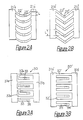
- the pair of parallel end parts are joined by multiple non-linear contact pieces, they may be shaped like the letter “C” or the letter “V” stood on end, as is shown in Figures 2A and 2B. Needless to say, two, three or more or any number of contact arms may be selected.
- the second socket-type electrical contact 30,30′ seeks to reinforce the elasticity by using each of the contact arms as a complete cantilever and to further reduce the inserting and extracting force of the force.
- Figures 3A and 3B show stamped, pre-formed socket-type electrical contacts 30,30′ respective of other embodiments of the invention.
- metal plate-shaped body 30 is equipped with a pair of parallel end parts 31a-31b and they are joined by multiple coupling arms 32a, 32b,...., 32n.
- contact beams 33a, 33b,...., 33n are formed between the adjoining coupling pieces from one side of coupling arm 32 -- for example from the insertion side of the pin.
- This metal plate-shaped body 30 is shaped to form a cylinder just as in Figure 1.
- Each of the coupling arms 32 may basically be coplanar with end parts 31, however, contact beam 33 is inclined inside as it faces the free side and the contact surface 34 is bent to form a spoon shape so that it makes contact with the outside surface of the pin (not shown).
- the contact 30′ in Figure 3B is basically the same as the one in Figure 3A. However, the coupling arm 32′ between the pair of parallel end parts 31a′-32b′ and the contact beams 33′ are completely separated. This means that each of the contact beams 33′ is used as a cantilever and extends from one of the end parts -- for example, from side 31a′ toward the other side 31b′ -- between the adjoining coupling arms 32′ and contact surface 34′ is formed near the free end.
- FIGS. 4A, 4B and 4C we shall use Figures 4A, 4B and 4C to illustrate the third socket-type electrical contact in the present invention.
- This third socket-type electrical contact 40,40′,40′′ is equipped with multiple contact beams and is designed to achieve low inserting and extracting force as well as a secure and reliable electrical connection with the pin.
- FIG 4A is a view of one embodiment of a suitable example of the socket-type electrical contact, i.e., the metal plate-shaped body 40 which is used to manufacture it.
- This plate-shaped body 40 is equipped with two straight coupling arms 42a and 42b between both parallel end parts 41a-41b. They are equipped with a pair of cantilevered contact beams 43 and 44 (which are parallel to coupling arm 42) on both sides of the center parts of this coupling arm 42, are separated from coupling arm 42 and face respectively end parts 41a-41b.
- Contact surfaces 45 and 46 are formed near both free ends of contact beams 43 and 44.
- the metal plate-shaped body 40 is shaped to form a cylinder and a socket-type electrical contact (not shown) is obtained which makes contact at eight locations on the four split positions on the outside of the pin by making the contact surfaces 45 and 46 of contact beams 43 and 44 protrude inwards.
- the free end of the contact beams 43 and 44, in particular, the free end of the side on which the pin is inserted should be bent sufficiently outwards so that no collision or fracture takes place when the pin is inserted.
- Figure 4B shows a metal plate-shaped body 40′.
- Contact beam 43′ is formed only on one side of each of the coupling arms 42′. The rest of the structure is basically the same.
- Figure 4C shows metal plate-shaped body 40′′. It is configured so that contact beams 43′′ and 44′′ are separate from the coupling arm 42′′ and is configured to form a cantilever which extends from both end parts 41a′′-41b′′ towards the other side.
- the free end parts of the contact beams 43" and 44" are made to protrude inward and so that two contact surfaces 45′′ and 46′′ are formed.
- the third socket-type electrical contacts (not shown) which makes use of these metal plate-shaped bodies 40, 40′ and 40′′ is bidirectional and provides the same low inserting and extracting force and the same reliable electrical contact no matter from what side the pin is inserted.
- the coupling arms 22, 22′ and 22′′ in Figure 1C or in Figures 2A and B may be shaped to form the letter "W" or in a zigzag and the contact surfaces may be formed at multiple bent points.
- the socket-type electrical contacts described above are all equipped with multiple cantilever-type contact arms. Therefore, the contact surfaces have outstanding elasticity and as a result the inserting and extracting force with the pin can be significantly reduced so that it is suitable for use in a connector when a large number of electrical contact pins must be inserted or extracted simultaneously.
Landscapes
- Coupling Device And Connection With Printed Circuit (AREA)
- Connecting Device With Holders (AREA)
Applications Claiming Priority (2)
| Application Number | Priority Date | Filing Date | Title |
|---|---|---|---|
| JP31470/90 | 1990-02-14 | ||
| JP3147090A JPH03236175A (ja) | 1990-02-14 | 1990-02-14 | ソケット型コンタクト |
Publications (2)
| Publication Number | Publication Date |
|---|---|
| EP0442639A2 true EP0442639A2 (fr) | 1991-08-21 |
| EP0442639A3 EP0442639A3 (en) | 1992-06-03 |
Family
ID=12332153
Family Applications (1)
| Application Number | Title | Priority Date | Filing Date |
|---|---|---|---|
| EP19910300873 Withdrawn EP0442639A3 (en) | 1990-02-14 | 1991-02-04 | Socket-type electrical contact |
Country Status (2)
| Country | Link |
|---|---|
| EP (1) | EP0442639A3 (fr) |
| JP (1) | JPH03236175A (fr) |
Cited By (17)
| Publication number | Priority date | Publication date | Assignee | Title |
|---|---|---|---|---|
| US5281571A (en) * | 1990-10-18 | 1994-01-25 | Monsanto Company | Herbicidal benzoxazinone- and benzothiazinone-substituted pyrazoles |
| US5735716A (en) * | 1996-09-18 | 1998-04-07 | Yazaki Corporation | Electrical connectors with delayed insertion force |
| EP0961355A1 (fr) * | 1998-05-27 | 1999-12-01 | Framatome Connectors International | Connecteur électrique avec un contact tubulaire fait d'une pluralité de membres en forme de V |
| US6464546B2 (en) | 2000-08-17 | 2002-10-15 | Smiths Group Plc | Electrical contacts |
| EP2280455A1 (fr) * | 2009-07-28 | 2011-02-02 | Tyco Electronics Corporation | Contact électrique avec un bras de contact |
| WO2012088968A1 (fr) * | 2010-12-30 | 2012-07-05 | Ni Quan | Élément de contact de prise compact et procédé de fabrication associé |
| DE102011112389A1 (de) * | 2011-09-02 | 2013-03-07 | Amphenol-Tuchel Electronics Gmbh | Metallisches Kontaktlamellengitter |
| DE102013217256B3 (de) * | 2013-08-29 | 2015-03-05 | Robert Bosch Gmbh | Buchse sowie Hochstromsteckverbindung, die eine solche Buchse aufweist |
| CN107317170A (zh) * | 2016-04-26 | 2017-11-03 | 苏州艾希迪连接器科技有限公司 | 电连接件及其加工方法 |
| CN107342472A (zh) * | 2016-05-03 | 2017-11-10 | 易时充有限公司 | 用于插槽式接触的套筒、使用该套筒的连接件以及制造方法 |
| CN107528149A (zh) * | 2017-08-29 | 2017-12-29 | 上海航天科工电器研究院有限公司 | 一种多触点式电连接器的母端子ⅰ及其加工方法 |
| CN107565251A (zh) * | 2017-08-29 | 2018-01-09 | 上海航天科工电器研究院有限公司 | 一种多触点式电连接器的母端子ⅱ及其加工方法 |
| CN107732508A (zh) * | 2017-11-16 | 2018-02-23 | 资阳中车电气科技有限公司 | 一种高压金属连接器插孔连接件及制作方法 |
| CN107819225A (zh) * | 2017-09-27 | 2018-03-20 | 上海航天科工电器研究院有限公司 | 一种多触点式冠簧端子 |
| GB2576507A (en) * | 2018-08-20 | 2020-02-26 | Technetix Bv | Connector |
| CN116111384A (zh) * | 2022-11-24 | 2023-05-12 | 中航光电科技股份有限公司 | 一种实现轴向弹性接触的可伸缩端子及连接器 |
| EP4213310A4 (fr) * | 2020-09-09 | 2024-09-18 | Phoenix Contact Asia-Pacific (Nanjing) Co., Ltd. | Borne de ressort à couronne, prise de connecteur électrique et connecteur électrique |
Families Citing this family (2)
| Publication number | Priority date | Publication date | Assignee | Title |
|---|---|---|---|---|
| JPH08203590A (ja) * | 1995-01-31 | 1996-08-09 | 光治 ▲頼▼ | 丸穴式ソケット |
| WO2011021298A1 (fr) * | 2009-08-20 | 2011-02-24 | 行田電線株式会社 | Pièce femelle de fixation de borne |
Family Cites Families (2)
| Publication number | Priority date | Publication date | Assignee | Title |
|---|---|---|---|---|
| GB2065993A (en) * | 1979-12-04 | 1981-07-01 | Pa Management Consult | Electrical connector |
| US4723923A (en) * | 1986-09-05 | 1988-02-09 | Augat Inc. | Low insertion, stamped and formed contact sleeve |
-
1990
- 1990-02-14 JP JP3147090A patent/JPH03236175A/ja active Pending
-
1991
- 1991-02-04 EP EP19910300873 patent/EP0442639A3/en not_active Withdrawn
Cited By (28)
| Publication number | Priority date | Publication date | Assignee | Title |
|---|---|---|---|---|
| US5281571A (en) * | 1990-10-18 | 1994-01-25 | Monsanto Company | Herbicidal benzoxazinone- and benzothiazinone-substituted pyrazoles |
| US5735716A (en) * | 1996-09-18 | 1998-04-07 | Yazaki Corporation | Electrical connectors with delayed insertion force |
| EP0961355A1 (fr) * | 1998-05-27 | 1999-12-01 | Framatome Connectors International | Connecteur électrique avec un contact tubulaire fait d'une pluralité de membres en forme de V |
| US6464546B2 (en) | 2000-08-17 | 2002-10-15 | Smiths Group Plc | Electrical contacts |
| EP2280455A1 (fr) * | 2009-07-28 | 2011-02-02 | Tyco Electronics Corporation | Contact électrique avec un bras de contact |
| CN101986470A (zh) * | 2009-07-28 | 2011-03-16 | 泰科电子公司 | 具有接触臂的电触头 |
| US8029326B2 (en) | 2009-07-28 | 2011-10-04 | Tyco Electronics Corporation | Electrical connector having an electrical contact with a contact arm |
| WO2012088968A1 (fr) * | 2010-12-30 | 2012-07-05 | Ni Quan | Élément de contact de prise compact et procédé de fabrication associé |
| DE102011112389A1 (de) * | 2011-09-02 | 2013-03-07 | Amphenol-Tuchel Electronics Gmbh | Metallisches Kontaktlamellengitter |
| DE102011112389B4 (de) * | 2011-09-02 | 2015-01-22 | Amphenol-Tuchel Electronics Gmbh | Metallisches Kontaktlamellengitter |
| DE102013217256B3 (de) * | 2013-08-29 | 2015-03-05 | Robert Bosch Gmbh | Buchse sowie Hochstromsteckverbindung, die eine solche Buchse aufweist |
| US9608341B2 (en) | 2013-08-29 | 2017-03-28 | Robert Bosch Gmbh | High-current plug-in connection with multi-arm contact lamellae |
| CN107317170A (zh) * | 2016-04-26 | 2017-11-03 | 苏州艾希迪连接器科技有限公司 | 电连接件及其加工方法 |
| FR3051078A1 (fr) * | 2016-05-03 | 2017-11-10 | Eaxtron | Manchon pour contact femelle, connecteur utilisant le manchon et procede de fabrication. |
| CN107342472A (zh) * | 2016-05-03 | 2017-11-10 | 易时充有限公司 | 用于插槽式接触的套筒、使用该套筒的连接件以及制造方法 |
| EP3252874A1 (fr) * | 2016-05-03 | 2017-12-06 | Eaxtron | Manchon pour contact femelle, connecteur utilisant le manchon et procédé de fabrication |
| CN107342472B (zh) * | 2016-05-03 | 2020-10-30 | 易时充有限公司 | 用于插槽式接触的套筒、使用该套筒的连接件以及制造方法 |
| CN107528149B (zh) * | 2017-08-29 | 2019-07-16 | 上海航天科工电器研究院有限公司 | 一种多触点式电连接器的母端子ⅰ及其加工方法 |
| CN107565251A (zh) * | 2017-08-29 | 2018-01-09 | 上海航天科工电器研究院有限公司 | 一种多触点式电连接器的母端子ⅱ及其加工方法 |
| CN107565251B (zh) * | 2017-08-29 | 2019-07-16 | 上海航天科工电器研究院有限公司 | 一种多触点式电连接器的母端子ⅱ及其加工方法 |
| CN107528149A (zh) * | 2017-08-29 | 2017-12-29 | 上海航天科工电器研究院有限公司 | 一种多触点式电连接器的母端子ⅰ及其加工方法 |
| CN107819225A (zh) * | 2017-09-27 | 2018-03-20 | 上海航天科工电器研究院有限公司 | 一种多触点式冠簧端子 |
| CN107819225B (zh) * | 2017-09-27 | 2019-10-18 | 上海航天科工电器研究院有限公司 | 一种多触点式冠簧端子 |
| CN107732508A (zh) * | 2017-11-16 | 2018-02-23 | 资阳中车电气科技有限公司 | 一种高压金属连接器插孔连接件及制作方法 |
| GB2576507A (en) * | 2018-08-20 | 2020-02-26 | Technetix Bv | Connector |
| EP4213310A4 (fr) * | 2020-09-09 | 2024-09-18 | Phoenix Contact Asia-Pacific (Nanjing) Co., Ltd. | Borne de ressort à couronne, prise de connecteur électrique et connecteur électrique |
| US12381348B2 (en) | 2020-09-09 | 2025-08-05 | Phoenix Contact Asia-Pacific (Nanjing) Co., Ltd. | Crown spring terminal, electrical connector socket, and electrical connector |
| CN116111384A (zh) * | 2022-11-24 | 2023-05-12 | 中航光电科技股份有限公司 | 一种实现轴向弹性接触的可伸缩端子及连接器 |
Also Published As
| Publication number | Publication date |
|---|---|
| EP0442639A3 (en) | 1992-06-03 |
| JPH03236175A (ja) | 1991-10-22 |
Similar Documents
| Publication | Publication Date | Title |
|---|---|---|
| EP0442639A2 (fr) | Contact électrique du type à douille | |
| US4591230A (en) | Electrical connector receptacle | |
| US11616329B2 (en) | Power connectors with receiving chamber | |
| US4416504A (en) | Contact with dual cantilevered arms with narrowed, complimentary tip portions | |
| EP0236490B1 (fr) | Connecteur electrique a reseau de broches | |
| EP0966062B1 (fr) | Contact à douille à déplacement d'isolation ayant une haute force de rétention | |
| EP0146295B1 (fr) | Connecteur en bordure pour porteur de circuits et bande de contacts pour celui-ci | |
| EP0043627A2 (fr) | Connecteur pour un câble plat à plusieurs conducteurs | |
| US20170179624A1 (en) | Power terminal with compliant pin for electrical power connector | |
| JPS5951491A (ja) | リブケ | |
| WO2015081986A1 (fr) | Connecteur et contact de réception de broche pour ledit connecteur | |
| EP0185471A2 (fr) | Pièce d'extrémité à déplacement d'isolant | |
| US5108304A (en) | Hermaphroditic terminal | |
| EP0593949A1 (fr) | Contact électrique à deux points ayant des pattes de précontrainte | |
| EP0542068B1 (fr) | Contact électrique femelle | |
| US6422878B1 (en) | Plug-type connector and method of manufacturing a plug-type connector | |
| EP0214022B1 (fr) | Contact pour connecteur | |
| US20060135003A1 (en) | Connector with improved dual beam contacts | |
| US4869685A (en) | Electrical connector having terminals with positive retention means and improved mating zones | |
| US6050863A (en) | Stamped and formed connector contacts | |
| EP0261839A2 (fr) | Assemblage de connecteur électrique à contact à ressort | |
| EP0515090B1 (fr) | Connecteur électrique ayant des moyens de rétention pour la plaque | |
| WO2000059073A1 (fr) | Borne electrique femelle a partie d'arret d'arc | |
| EP3254338A1 (fr) | Contact électrique | |
| JPH0531275B2 (fr) |
Legal Events
| Date | Code | Title | Description |
|---|---|---|---|
| PUAI | Public reference made under article 153(3) epc to a published international application that has entered the european phase |
Free format text: ORIGINAL CODE: 0009012 |
|
| AK | Designated contracting states |
Kind code of ref document: A2 Designated state(s): DE FR NL |
|
| PUAL | Search report despatched |
Free format text: ORIGINAL CODE: 0009013 |
|
| AK | Designated contracting states |
Kind code of ref document: A3 Designated state(s): DE FR NL |
|
| STAA | Information on the status of an ep patent application or granted ep patent |
Free format text: STATUS: THE APPLICATION IS DEEMED TO BE WITHDRAWN |
|
| 18D | Application deemed to be withdrawn |
Effective date: 19921204 |