EP0442660B1 - Surface d'appui avec air d'un glisseur avec noyau de tête et procédé pour fabriquer celui-ci - Google Patents
Surface d'appui avec air d'un glisseur avec noyau de tête et procédé pour fabriquer celui-ci Download PDFInfo
- Publication number
- EP0442660B1 EP0442660B1 EP91300989A EP91300989A EP0442660B1 EP 0442660 B1 EP0442660 B1 EP 0442660B1 EP 91300989 A EP91300989 A EP 91300989A EP 91300989 A EP91300989 A EP 91300989A EP 0442660 B1 EP0442660 B1 EP 0442660B1
- Authority
- EP
- European Patent Office
- Prior art keywords
- etching
- air bearing
- disk
- head core
- slider
- Prior art date
- Legal status (The legal status is an assumption and is not a legal conclusion. Google has not performed a legal analysis and makes no representation as to the accuracy of the status listed.)
- Expired - Lifetime
Links
- 238000004519 manufacturing process Methods 0.000 title claims description 5
- 238000005530 etching Methods 0.000 claims description 52
- 238000000034 method Methods 0.000 description 31
- NBIIXXVUZAFLBC-UHFFFAOYSA-N Phosphoric acid Chemical compound OP(O)(O)=O NBIIXXVUZAFLBC-UHFFFAOYSA-N 0.000 description 30
- 229910000859 α-Fe Inorganic materials 0.000 description 26
- 229910000147 aluminium phosphate Inorganic materials 0.000 description 15
- -1 amine compound Chemical class 0.000 description 12
- 239000013078 crystal Substances 0.000 description 12
- 239000000463 material Substances 0.000 description 12
- 239000000243 solution Substances 0.000 description 10
- 238000003486 chemical etching Methods 0.000 description 7
- 239000000725 suspension Substances 0.000 description 7
- 229920002120 photoresistant polymer Polymers 0.000 description 6
- 239000007864 aqueous solution Substances 0.000 description 5
- 230000001965 increasing effect Effects 0.000 description 5
- VYPSYNLAJGMNEJ-UHFFFAOYSA-N Silicium dioxide Chemical compound O=[Si]=O VYPSYNLAJGMNEJ-UHFFFAOYSA-N 0.000 description 4
- 238000000137 annealing Methods 0.000 description 4
- 230000006378 damage Effects 0.000 description 4
- 239000000314 lubricant Substances 0.000 description 4
- ZMANZCXQSJIPKH-UHFFFAOYSA-N Triethylamine Chemical compound CCN(CC)CC ZMANZCXQSJIPKH-UHFFFAOYSA-N 0.000 description 3
- 238000013459 approach Methods 0.000 description 3
- 238000005229 chemical vapour deposition Methods 0.000 description 3
- 230000003247 decreasing effect Effects 0.000 description 3
- HZAXFHJVJLSVMW-UHFFFAOYSA-N 2-Aminoethan-1-ol Chemical compound NCCO HZAXFHJVJLSVMW-UHFFFAOYSA-N 0.000 description 2
- VVJKKWFAADXIJK-UHFFFAOYSA-N Allylamine Chemical compound NCC=C VVJKKWFAADXIJK-UHFFFAOYSA-N 0.000 description 2
- PAYRUJLWNCNPSJ-UHFFFAOYSA-N Aniline Chemical compound NC1=CC=CC=C1 PAYRUJLWNCNPSJ-UHFFFAOYSA-N 0.000 description 2
- QUSNBJAOOMFDIB-UHFFFAOYSA-N Ethylamine Chemical compound CCN QUSNBJAOOMFDIB-UHFFFAOYSA-N 0.000 description 2
- QAOWNCQODCNURD-UHFFFAOYSA-N Sulfuric acid Chemical compound OS(O)(=O)=O QAOWNCQODCNURD-UHFFFAOYSA-N 0.000 description 2
- 239000002253 acid Substances 0.000 description 2
- 150000007513 acids Chemical class 0.000 description 2
- 150000001412 amines Chemical class 0.000 description 2
- WGQKYBSKWIADBV-UHFFFAOYSA-N benzylamine Chemical compound NCC1=CC=CC=C1 WGQKYBSKWIADBV-UHFFFAOYSA-N 0.000 description 2
- HQABUPZFAYXKJW-UHFFFAOYSA-N butan-1-amine Chemical compound CCCCN HQABUPZFAYXKJW-UHFFFAOYSA-N 0.000 description 2
- 229910052681 coesite Inorganic materials 0.000 description 2
- 229910052906 cristobalite Inorganic materials 0.000 description 2
- 229910003460 diamond Inorganic materials 0.000 description 2
- 239000010432 diamond Substances 0.000 description 2
- 239000000945 filler Substances 0.000 description 2
- 239000011521 glass Substances 0.000 description 2
- 238000007654 immersion Methods 0.000 description 2
- 238000005470 impregnation Methods 0.000 description 2
- 239000010687 lubricating oil Substances 0.000 description 2
- 238000000059 patterning Methods 0.000 description 2
- WGYKZJWCGVVSQN-UHFFFAOYSA-N propylamine Chemical compound CCCN WGYKZJWCGVVSQN-UHFFFAOYSA-N 0.000 description 2
- 239000000377 silicon dioxide Substances 0.000 description 2
- 238000004544 sputter deposition Methods 0.000 description 2
- 229910052682 stishovite Inorganic materials 0.000 description 2
- 238000003860 storage Methods 0.000 description 2
- 239000010936 titanium Substances 0.000 description 2
- 229910052719 titanium Inorganic materials 0.000 description 2
- 229910052905 tridymite Inorganic materials 0.000 description 2
- XLYOFNOQVPJJNP-UHFFFAOYSA-N water Substances O XLYOFNOQVPJJNP-UHFFFAOYSA-N 0.000 description 2
- 230000005355 Hall effect Effects 0.000 description 1
- RTAQQCXQSZGOHL-UHFFFAOYSA-N Titanium Chemical compound [Ti] RTAQQCXQSZGOHL-UHFFFAOYSA-N 0.000 description 1
- GSEJCLTVZPLZKY-UHFFFAOYSA-N Triethanolamine Chemical compound OCCN(CCO)CCO GSEJCLTVZPLZKY-UHFFFAOYSA-N 0.000 description 1
- 239000006061 abrasive grain Substances 0.000 description 1
- 125000001931 aliphatic group Chemical group 0.000 description 1
- 239000004411 aluminium Substances 0.000 description 1
- 229910052782 aluminium Inorganic materials 0.000 description 1
- XAGFODPZIPBFFR-UHFFFAOYSA-N aluminium Chemical compound [Al] XAGFODPZIPBFFR-UHFFFAOYSA-N 0.000 description 1
- PNEYBMLMFCGWSK-UHFFFAOYSA-N aluminium oxide Inorganic materials [O-2].[O-2].[O-2].[Al+3].[Al+3] PNEYBMLMFCGWSK-UHFFFAOYSA-N 0.000 description 1
- 150000004982 aromatic amines Chemical class 0.000 description 1
- 230000015572 biosynthetic process Effects 0.000 description 1
- AOWKSNWVBZGMTJ-UHFFFAOYSA-N calcium titanate Chemical compound [Ca+2].[O-][Ti]([O-])=O AOWKSNWVBZGMTJ-UHFFFAOYSA-N 0.000 description 1
- 238000004140 cleaning Methods 0.000 description 1
- 239000011248 coating agent Substances 0.000 description 1
- 238000000576 coating method Methods 0.000 description 1
- 238000004891 communication Methods 0.000 description 1
- 239000002131 composite material Substances 0.000 description 1
- 230000007547 defect Effects 0.000 description 1
- 150000004985 diamines Chemical class 0.000 description 1
- ZBCBWPMODOFKDW-UHFFFAOYSA-N diethanolamine Chemical compound OCCNCCO ZBCBWPMODOFKDW-UHFFFAOYSA-N 0.000 description 1
- 229940043237 diethanolamine Drugs 0.000 description 1
- HPNMFZURTQLUMO-UHFFFAOYSA-N diethylamine Chemical compound CCNCC HPNMFZURTQLUMO-UHFFFAOYSA-N 0.000 description 1
- WEHWNAOGRSTTBQ-UHFFFAOYSA-N dipropylamine Chemical compound CCCNCCC WEHWNAOGRSTTBQ-UHFFFAOYSA-N 0.000 description 1
- 238000009826 distribution Methods 0.000 description 1
- 239000000428 dust Substances 0.000 description 1
- 230000000694 effects Effects 0.000 description 1
- 238000000866 electrolytic etching Methods 0.000 description 1
- 230000002708 enhancing effect Effects 0.000 description 1
- 229940031098 ethanolamine Drugs 0.000 description 1
- 239000012530 fluid Substances 0.000 description 1
- 238000010438 heat treatment Methods 0.000 description 1
- 230000001939 inductive effect Effects 0.000 description 1
- 238000010884 ion-beam technique Methods 0.000 description 1
- 239000010410 layer Substances 0.000 description 1
- 230000001050 lubricating effect Effects 0.000 description 1
- 238000003754 machining Methods 0.000 description 1
- 230000000873 masking effect Effects 0.000 description 1
- 230000008018 melting Effects 0.000 description 1
- 238000002844 melting Methods 0.000 description 1
- 229910052751 metal Inorganic materials 0.000 description 1
- 239000002184 metal Substances 0.000 description 1
- 239000000203 mixture Substances 0.000 description 1
- 239000003960 organic solvent Substances 0.000 description 1
- 239000002245 particle Substances 0.000 description 1
- 238000001020 plasma etching Methods 0.000 description 1
- 230000005855 radiation Effects 0.000 description 1
- 238000007650 screen-printing Methods 0.000 description 1
- 230000009528 severe injury Effects 0.000 description 1
- 238000000992 sputter etching Methods 0.000 description 1
- 230000003068 static effect Effects 0.000 description 1
- 239000000126 substance Substances 0.000 description 1
- 239000000758 substrate Substances 0.000 description 1
- 239000002344 surface layer Substances 0.000 description 1
- 230000003746 surface roughness Effects 0.000 description 1
- 238000004381 surface treatment Methods 0.000 description 1
- 239000010409 thin film Substances 0.000 description 1
- 150000004992 toluidines Chemical class 0.000 description 1
- 229940086542 triethylamine Drugs 0.000 description 1
- 229960004418 trolamine Drugs 0.000 description 1
- 238000001771 vacuum deposition Methods 0.000 description 1
- 238000007740 vapor deposition Methods 0.000 description 1
Images


Classifications
-
- G—PHYSICS
- G11—INFORMATION STORAGE
- G11B—INFORMATION STORAGE BASED ON RELATIVE MOVEMENT BETWEEN RECORD CARRIER AND TRANSDUCER
- G11B21/00—Head arrangements not specific to the method of recording or reproducing
- G11B21/16—Supporting the heads; Supporting the sockets for plug-in heads
- G11B21/20—Supporting the heads; Supporting the sockets for plug-in heads while the head is in operative position but stationary or permitting minor movements to follow irregularities in surface of record carrier
- G11B21/21—Supporting the heads; Supporting the sockets for plug-in heads while the head is in operative position but stationary or permitting minor movements to follow irregularities in surface of record carrier with provision for maintaining desired spacing of head from record carrier, e.g. fluid-dynamic spacing, slider
-
- G—PHYSICS
- G11—INFORMATION STORAGE
- G11B—INFORMATION STORAGE BASED ON RELATIVE MOVEMENT BETWEEN RECORD CARRIER AND TRANSDUCER
- G11B5/00—Recording by magnetisation or demagnetisation of a record carrier; Reproducing by magnetic means; Record carriers therefor
- G11B5/48—Disposition or mounting of heads or head supports relative to record carriers ; arrangements of heads, e.g. for scanning the record carrier to increase the relative speed
- G11B5/58—Disposition or mounting of heads or head supports relative to record carriers ; arrangements of heads, e.g. for scanning the record carrier to increase the relative speed with provision for moving the head for the purpose of maintaining alignment of the head relative to the record carrier during transducing operation, e.g. to compensate for surface irregularities of the latter or for track following
- G11B5/60—Fluid-dynamic spacing of heads from record-carriers
- G11B5/6005—Specially adapted for spacing from a rotating disc using a fluid cushion
-
- G—PHYSICS
- G11—INFORMATION STORAGE
- G11B—INFORMATION STORAGE BASED ON RELATIVE MOVEMENT BETWEEN RECORD CARRIER AND TRANSDUCER
- G11B33/00—Constructional parts, details or accessories not provided for in the other groups of this subclass
- G11B33/14—Reducing influence of physical parameters, e.g. temperature change, moisture, dust
-
- G—PHYSICS
- G11—INFORMATION STORAGE
- G11B—INFORMATION STORAGE BASED ON RELATIVE MOVEMENT BETWEEN RECORD CARRIER AND TRANSDUCER
- G11B5/00—Recording by magnetisation or demagnetisation of a record carrier; Reproducing by magnetic means; Record carriers therefor
- G11B5/84—Processes or apparatus specially adapted for manufacturing record carriers
Definitions
- This invention relates to the field of magnetic head systems, in particular head core sliders. More particularly, the present invention relates to improvements for reducing stiction in a magnetic head system. More particularly, the present invention relates to a technique for reducing stiction by texturing the surface of the air bearing on the magnetic head slider which supports the magnetic head and lies opposite the disk surface.
- the magnetic head In conventional magnetic head systems, the magnetic head consists of an electromagnetic arrangement for writing, reading or erasing data on a magnetizable storage medium, movable relative thereto, such as a magnetic disk.
- a magnetizable storage medium movable relative thereto
- Known kinds of magnetic head arrangements include ring electromagnets with an air gap, Hall effect components, magneto-resistive components and inductive electromagnetic arrangements.
- the magnetic head is attached to a slider and lies opposite the disk surface.
- Rotating magnetic disks of the type in which the magnetic head is in contact with the disk surface when the disk is at rest and flies above the disk surface when the disk is rotating at its operating speed are well known in the field.
- the magnetic head which is supported on a slider, rides on a cushion or bearing of air above the disk surface when the disk is rotating at its operating speed.
- the slider is movable radially on the disk to be positioned over a selected one of a group of concentric recording tracks.
- the slider is carried on a suspension assembly connected ultimately to an actuator.
- the slider and its suspension during normal operation are relatively rigid, but are somewhat fragile when subjected to tangential forces.
- the slider is biased against the disk surface by a small force from the suspension when the disk is not rotating.
- the slider is in sliding contact with the disk surface from the time that rotation of the magnetic disk is initiated, until the disk reaches a rotational speed sufficient to cause the slider to ride on the air bearing.
- the slider also contacts the disk surface when the rotation of the disk is slowed to a stop and the rotational speed of the disk falls below that necessary to create the air bearing.
- a lubricant is often maintained on the disk surface to prevent damage to the head and the disk during starting and stopping of the disk.
- An existing problem with such magnetic disks is that after the slider has been in stationary contact with the disk surface for just a short period of time, the slider tends to resist translational movement or stick to the disk surface. This adherence or “stiction” is known to be caused by a variety of factors, including static friction and viscous shear forces. However, “stiction” is aggravated by the presence of the lubricant material on the disk surface which tends to puddle up between the disk surface and the slider when the disk is not in motion and the slider rests on the disk surface.
- disk rotation is started very slowly so that the slider gradually breaks free from the disk surface.
- This approach is undesirable because it requires a relatively long period of time to bring the magnetic disk up to operating speed and additionally imparts tangential forces to the suspensions, which is the direction in which they are structurally weakest.
- the slider and its suspension structure are moved a slight amount in each disk radial direction, a number of times, prior to applying power to rotate the disks at start up. This controlled micromotion has been found to be effective only in a few cases.
- head-to-disk spacing (flying height).
- the head-to-disk spacing is so decreased that the magnetic head slider comes into contact with the magnetic disk surface frequently during the starting and stopping operation.
- the flying height may be so decreased that, even during the flying period, if the magnetic disk has flaws, such as tiny projections or dust on the surface, the magnetic disk may be contacted. Under these circumstances, the reliability of a magnetic recording device greatly depends on the sliding characteristics of the magnetic head slider.
- US-A-4,549,238 describes a texturing technique for alumina-titanium carbine thin film heads using a CF4 plasma etching process to selectively remove the surface layer titanium carbine particles, to produce small pits.
- the intention of this process is to reduce the effective hardness of the slider instead of reducing stiction, and thereby reduce wear of the disk upon landing and taking off.
- JP-A-59-148179 describes a process in which the ferrite of the magnetic head rail surface is etched using a mask of crystal-grain sized aluminium portions, to give a rough surface containing small recesses.
- JP-A-54-23517 defines an appropriate surface roughness, of about 0.1 ⁇ m, for reducing sticking of the recording medium and the slider.
- the present invention seeks to provide an improved technique to reduce stiction which retards take-off and displaces critical lubricants in a magnetic head system.
- the present invention is set out in claim 1.
- the reliable life of both the disk and the magnetic head can be significantly increased, while the data density, in bits per area unit of magnetic storage disks, can be increased since the distance between the magnetic head and disk surface may be reduced.
- the present invention utilizes a photoresist, such as utilized in making printed micro-circuits, to form a pattern.
- the surface may then be etched to texture it according to the pattern to form the anti-stiction properties.
- Many controlled and reproducible patterns are possible, as well as controlled etching depth.
- Figure 1 is a perspective view of one example of a head core slider for a rigid magnetic disk drive illustrating the air bearing.
- Figure 2 is a plan view of the magnetic head slider illustrating a pattern created on the air bearing surface, in accordance with a second embodiment of the present invention.
- Figure 3 is a plan view of the magnetic head slider illustrating an alternate pattern created on the air bearing surface, in accordance with the second embodiment of the present invention.
- Figure 4 is a plan view of the magnetic head slider illustrating another alternate pattern formed on the air bearing surface, in accordance with the second embodiment of the present invention.
- Figure 5 is a plan view of the magnetic head slider illustrating a pattern varied on different regions of the air bearing surface, in accordance with the second embodiment of the present invention.
- Figure 6 is graphical representation illustrating a relationship between the concentration of a phosphoric acid solution and the etching rate, in accordance with a preferred etching technique. The illustrated relationship is for an exemplary plane (110) of the surface of a ferrite single crystal.
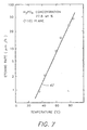
- Figure 7 is a graphical representation illustrating a relationship between the rate of etching with the phosphoric acid and the etching temperature in accordance with a preferred etching technique. The illustrated relationship is for an exemplary plane (110) of the surface of a ferrite single crystal.
- FIG. 1 illustrates generally a magnetic slider 10.
- the slider 10 may be either a monolithic slider composed of polycrystalline ferrites or a single crystal material such as ferrite.
- the slider 10 may also be formed of a composite material such as calcium-titanate with alumina.
- Any of the before-mentioned type sliders 10 are exemplary of bulk type core sliders utilized by a floating-type magnetic head in a rigid magnetic disk drive.
- the slider 10 is integrally formed comprising a slider body 12 and a yoke portion 14.
- the yoke portion in cross section is C-shaped.
- a recording medium such as a magnetic disk rotates adjacent one surface 16 of the slider body 12.
- the core slider 10 has a center rail 20 which is formed between the air bearing portions 18a, 18b.
- the center rail 20 serves as a track portion whose surface has the same height as the air bearing portions 18a, 18b.
- This track portion includes the magnetic gap 19 used for recording purposes.
- the magnetic gap 19 and yoke 14 may of course be located in any suitable position.
- the center rail of the core slider 10 which carries the yoke 14 and the gap 19 may alternatively be omitted and the yoke 14 and gap 19 integrated with one of the side rails.
- the side rails would continue to be air bearing surfaces.
- a second embodiment of the present invention utilizes the uniform etching characteristics of single crystal material such as ferrite. Patterns which are enlarged for clarity in Figures 2, 3, 4 and 5, are created on the surface of the air bearing portions 18a, 18b, using conventional photolithographic techniques.
- An etching mask is formed of a positive or negative type photoresist, or formed of a suitable masking material such as Cr or SiO or SiO 2 , by vacuum vapor deposition, sputtering, chemical vapor deposition (CVD), or other techniques known to those skilled in the art.
- This method of forming a mask and the material of the mask are suitably selected in terms of ease and cost of formation and the adhesiveness of the mask to the surface.
- the ferrite material partially covered by the etching mask is then subjected to an etching process to remove a suitable amount of stock from the non-masked portions of the surface.
- One such preferred method is described in greater detail at a later point in this application.
- the ferrite material is usually etched by an ordinary electrolytic etching or chemical etching method, such as chemical etching, laser-assisted chemical etching, reactive ion-milling, etc.
- an ordinary electrolytic etching or chemical etching method such as chemical etching, laser-assisted chemical etching, reactive ion-milling, etc.
- a variety of controlled and reproducible patterns are possible. It is also possible to control the depth of the pattern.
- Figures 2, 3 and 4 illustrate the surface of the air bearing portions 18a, 18b patterned in four different exemplary patterns.
- the second embodiment advantageously produces carefully controlled patterns of predetermined height with minimum material removal, with complete protection of the region around the gap 19, relatively independent of slider material composition and crystallographic variations.
- the etched patterns are preferably formed as repetitions of non-circular curves, as shown at 21 and 23.
- the surface may be textured with any pattern whereby a recessed area 28 of the pattern forms a continuous boundary connecting the edges of the air bearing and thus forming a path to facilitate fluid communication across the surface of the air bearing to distribute ambient pressure.
- the recessed portion 28 preferably extends continuously from an outer edge 30 to an inner edge 32.
- the etched patterns are preferably formed as regular geometric shapes of varying size, such as shown at 25 and 27.
- the pattern may vary in different regions of the air bearing surface.
- the etched pattern must advantageously provide a maximum reduction of stiction at a leading edge 36 as well as provide stability at a trailing edge 38.
- the etched pattern may also have smaller geometric shapes at the leading edge and larger geometric shapes at the trailing edge.
- the patterns are chosen to emulate a random variation. Although such randomness is advantageous, even uniform geometric patterning of the air bearing surface is advantageous in reducing stiction.
- the surface of an exemplary Mn-Zn ferrite single crystal may be exposed to a solution which contains an amine compound, prior to forming the etching mask on the surface of the ferrite single crystal.
- this preliminary treatment is carried out after the surface is cleaned with an organic solvent or pure water.
- the Mn-Zn ferrite single crystal may also preferably be annealed prior to the preliminary treatment.
- the amine compound is preferably selected from alkanol amines such as ethanol amine, diethanol amine or triethanol amine.
- alkanol amines such as ethanol amine, diethanol amine or triethanol amine.
- other amine compounds for example: aliphatic primary amines such as ethyl amine, propyl amine and butyl amine; aliphatic secondary amines such as diethyl amine and dipropyl amine; aliphatic tertiary amines such as triethyl amine; aliphatic unsaturated amines such as allyl amine; alicyclic amines; diamines; triamines; or aromatic amines such as aniline, toluidine and benzyl amine.
- the selected amine compound is generally used as an aqueous solution.
- the monocrystalline surface of the Mn-Zn ferrite is immersed in the aqueous solution and cleansed.
- the concentration and temperature of the amine compound and the immersion time are determined based on the specific amine compound used and the cleaning result desired. The above steps assure increased adhesion between the etching mask and the relevant surface of the Mn-Zn ferrite single crystal, thereby enhancing the dimensional accuracy of the texturing.
- This method of etching may be applied to both a single crystal of ferrite or a monocrystalline portion of a Mn-Zn ferrite material.
- a monocrystalline portion of a Mn-Zn ferrite is used, an exposed monocrystalline surface is usually mirror-ground to a desired smoothness with a diamond abrasive grain, in a conventionally known manner.
- the diamond abrasive used preferably has a grain size of four microns or less.
- a strain adjacent to the surface of the ferrite single crystal to be chemically etched lowers the etching rate of the surface and degrades the dimensional accuracy of the etched crystal. Therefore, it is recommended to remove such a strain prior to the chemical etching process.
- This may be accomplished by preliminary chemical or ion-beam etching, or annealing (heat treatment) in an inert atmosphere such as N 2 .
- annealing heat treatment
- the annealing operation is generally carried out at a temperature between 200°C and 600°C, advantageously, between 250°C and 550°C, for at least 30 minutes.
- the upper limit of the annealing temperature is below the melting point of the glass filler.
- the preliminary treatment with the amine compound solution may be replaced by a preliminary treatment with a solution of phosphoric acid, which is also effected prior to the application of the etching mask to the surface of the Mn-Zn ferrite single crystal.
- a preliminary treatment with a solution of phosphoric acid which is also effected prior to the application of the etching mask to the surface of the Mn-Zn ferrite single crystal.
- the appropriate etching mask is formed on the treated surface, by any known method such as screen printing, or the like. Such a method is selected according to the patterning accuracy and cost required.
- the etching mask may advantageously be formed by exposing a layer of a photo resist to radiation through an appropriate photomask.
- the photo resist may be either a positive type or a negative type.
- the etching mask may be formed of a suitable metal such as Cr, or SiO or SiO 2 , by vacuum deposition, sputtering or CVD.
- the degree of adhesion of the mask to the ferrite surface, the ease and the cost of forming such a mask are contributing factors which determine the type of material and method used in forming such a mask.
- the monocrystalline surface of the Mn-Zn ferrite with the appropriate etching mask is then subjected to a chemical etching process.
- the chemical etching process to form the pattern is carried out, most preferably by using an aqueous solution consisting of water and mainly phosphoric acid.
- a small amount of other acids such as sulfuric acid may also be used in addition to phosphoric acid. If the content of phosphoric acid is 80% or more with respect to the entire amount of the acids contained in the aqueous solution, the balance is considered to be mainly of phosphoric acid.
- the etching rate is very high when the phosphoric acid concentration exceeds 80%. It can also be noted that when the concentration exceeds 80% the rate of increase is exponential. In such cases, it is rather difficult to accurately control the etching amount.
- the etching rate is also influenced by the etching temperature, as indicated at 42, in the graph of Figure 7.
- the etching time is maintained at a minimum because where the etching mask is formed of a photo resist, the adhesion between the etching mask and the ferrite surface is decreased due to expansion of the photo resist during the period that it is immersed in the etching solution. Additionally, it is also desireable to minimize the etching time, for improved dimensional accuracy of the etched portion.
- the etching temperature should be 90°C or lower, preferably ranging between 50°C and 90°C.
- the concentration of phosphoric acid in the etching solution should preferably be maintained between 5-80%.
- the etching temperature and the phosphoric acid concentration of the etching solution may not be limited to those indicated above, particularly when the amount of etching is comparatively smaller and when the etching mask has a high degree of adhesion to the ferrite surface. In this case, other factors also contribute to achieve optimum etching conditions.
Landscapes
- Adjustment Of The Magnetic Head Position Track Following On Tapes (AREA)
Claims (7)
- Glisseur avec noyau de tête pour une mémoire à disque magnétique comportant un corps de glissement (10) présentant une surface à coussinet d'air (18a, 18b) qui, dans une mémoire à disque, vient périodiquement en contact avec le disque de la mémoire, ladite surface (18a, 18b) étant texturée par attaque chimique pour qu'elle ne soit pas lisse, caractérisé en ce que ladite surface (18a, 18b) est texturée selon un modèle gravé prédéterminé et reproductible comprenant des régions évidées (28; 25, 27, 34) définies par des limites courbées (21, 23).
- Glisseur avec noyau de tête selon la revendication 1, où lesdites régions évidées (28; 25, 27, 34) ont différentes tailles.
- Glisseur avec noyau de tête selon la revendication 1 ou la revendication 2, dans lequel lesdites parties évidées (28; 25, 27, 34) ont des différence en hauteur relativement à un plan moyen de ladite surface à coussinet d'air, dans une plage de 25 à 250 nm (1 à 10 micropouces).
- Glisseur avec noyau de tête selon l'une des revendications 1 à 3, dans lequel les tailles moyennes desdites zones évidées (28; 25, 27, 34) varient dans différentes zones de ladite surface à coussinet d'air.
- Glisseur avec noyau de tête selon l'une des revendications 1 à 4, dans lequel lesdites limites courbées sont des limites continues (21, 23) reliant les bords de ladite surface à coussinet d'air.
- Glisseur avec noyau de tête selon l'une des revendications 1 à 4, dans lequel lesdites régions évidées forment un dessin de formes géométriques fermées d'une seule configuration ou de configurations différentes.
- Procédé de fabrication d'un glisseur avec noyau de tête selon l'une des revendications 1 à 6, comprenant la texture de ladite surface à coussinet d'air pour former ledit dessin de régions évidées (28; 25, 27, 34) par attaque chimique en utilisant un masque.
Applications Claiming Priority (2)
| Application Number | Priority Date | Filing Date | Title |
|---|---|---|---|
| US07/481,556 US5079657A (en) | 1990-02-15 | 1990-02-15 | Textured air bearing surface |
| US481556 | 1990-02-15 |
Publications (3)
| Publication Number | Publication Date |
|---|---|
| EP0442660A2 EP0442660A2 (fr) | 1991-08-21 |
| EP0442660A3 EP0442660A3 (en) | 1993-02-10 |
| EP0442660B1 true EP0442660B1 (fr) | 1996-07-17 |
Family
ID=23912421
Family Applications (1)
| Application Number | Title | Priority Date | Filing Date |
|---|---|---|---|
| EP91300989A Expired - Lifetime EP0442660B1 (fr) | 1990-02-15 | 1991-02-06 | Surface d'appui avec air d'un glisseur avec noyau de tête et procédé pour fabriquer celui-ci |
Country Status (5)
| Country | Link |
|---|---|
| US (1) | US5079657A (fr) |
| EP (1) | EP0442660B1 (fr) |
| JP (1) | JPH04216377A (fr) |
| KR (1) | KR920000050A (fr) |
| DE (1) | DE69120839T2 (fr) |
Cited By (2)
| Publication number | Priority date | Publication date | Assignee | Title |
|---|---|---|---|---|
| US7106556B2 (en) | 2003-06-24 | 2006-09-12 | Seagate Technology Llc | Slider configured for rapid bearing stabilization during ramp load operations |
| US7477486B1 (en) | 2005-12-07 | 2009-01-13 | Western Digital (Fremont), Llc | Air bearing slider with a side pad having a shallow recess depth |
Families Citing this family (60)
| Publication number | Priority date | Publication date | Assignee | Title |
|---|---|---|---|---|
| JP2751609B2 (ja) * | 1990-09-21 | 1998-05-18 | 三菱電機株式会社 | 磁気ヘッドスライダ及びその支持機構 |
| JP3106210B2 (ja) * | 1991-03-29 | 2000-11-06 | ミネベア株式会社 | 浮動型磁気ヘッドスライダ |
| US5239952A (en) * | 1991-11-08 | 1993-08-31 | Atsugi Unisia Corporation | Valve actuating apparatus |
| JPH0724096B2 (ja) * | 1992-05-29 | 1995-03-15 | ティーディーケイ株式会社 | 磁気ヘッドの加工方法 |
| JP3092686B2 (ja) * | 1992-08-19 | 2000-09-25 | コマッグ・インコーポレイテッド | 磁気記録ヘッドスライダ及びその製造方法 |
| TW226464B (fr) * | 1992-12-29 | 1994-07-11 | Ibm | |
| US5388017A (en) * | 1993-01-29 | 1995-02-07 | International Business Machines Corporation | Disk file with air-bearing slider having skids |
| US5567864A (en) * | 1993-02-04 | 1996-10-22 | Sunward Technologies, Inc. | Method and apparatus for calibration of a transducer flying height measurement instrument |
| US5654850A (en) * | 1993-05-18 | 1997-08-05 | Applied Magnetics Corp. | Carbon overcoat with electrically conductive adhesive layer for magnetic head sliders |
| US5336550A (en) * | 1993-05-18 | 1994-08-09 | Applied Magnetics Corporation | Carbon overcoat for magnetic head sliders |
| TW279972B (fr) * | 1993-06-21 | 1996-07-01 | Komag Inc | |
| US6330131B1 (en) * | 1993-09-17 | 2001-12-11 | Read-Rite Corporation | Reduced stiction air bearing slider |
| US5452166A (en) * | 1993-10-01 | 1995-09-19 | Applied Magnetics Corporation | Thin film magnetic recording head for minimizing undershoots and a method for manufacturing the same |
| US5768076A (en) * | 1993-11-10 | 1998-06-16 | International Business Machines Corporation | Magnetic recording disk having a laser-textured surface |
| TW300879B (fr) * | 1993-11-10 | 1997-03-21 | Ibm | |
| JP3125127B2 (ja) * | 1994-07-21 | 2001-01-15 | ミネベア株式会社 | 浮動型磁気ヘッドの表面仕上げ方法 |
| JP3219947B2 (ja) | 1994-09-29 | 2001-10-15 | アルプス電気株式会社 | 浮上式磁気ヘッド |
| US5550693A (en) * | 1994-10-31 | 1996-08-27 | International Business Machines Corporation | Air bearing slider having projections that provide minimal actual contact area |
| US5774303A (en) * | 1995-03-24 | 1998-06-30 | Stormedia, Inc. | Sputter induced micro-texturing enhancement for magnetic head structures |
| US5815346A (en) * | 1995-06-12 | 1998-09-29 | Maxtor Corporation | Textured slider surface |
| US5853959A (en) * | 1996-08-09 | 1998-12-29 | Seagate Technology, Inc. | Method of fabricating a contoured slider surface feature with a single mask |
| US5768055A (en) * | 1996-09-19 | 1998-06-16 | Sae Magnetics (H.K.) Ltd. | Magnetic recording head having a carbon overcoat array on slider air bearings surfaces |
| US5796551A (en) * | 1996-10-16 | 1998-08-18 | International Business Machines Corporation | Landing pads for air bearing sliders and method for making the same |
| JPH10172125A (ja) * | 1996-12-09 | 1998-06-26 | Alps Electric Co Ltd | 磁気ヘッド、この磁気ヘッドを備えた磁気記録再生装置および磁気ヘッドの製造方法 |
| US5967880A (en) * | 1997-01-03 | 1999-10-19 | International Business Machines Corporation | Method and apparatus for ultrasonically texturing ABS of magnetic head of hard disk drive |
| JP3466041B2 (ja) | 1997-03-03 | 2003-11-10 | アルプス電気株式会社 | 磁気ヘッドおよびその製造方法 |
| US5870251A (en) * | 1997-04-14 | 1999-02-09 | Seagate Technology, Inc. | Taperless/crown free/air bearing design |
| US6212042B1 (en) | 1997-06-27 | 2001-04-03 | Seagate Technology Llc | Slider having air bearing surface which includes pads for disk storage system |
| WO1999009547A1 (fr) | 1997-08-15 | 1999-02-25 | Seagate Technology, Inc. | Palette de survol pour systeme de memoire a disque |
| JPH1186483A (ja) * | 1997-09-04 | 1999-03-30 | Fujitsu Ltd | ヘッドスライダ及びディスク装置 |
| US5861196A (en) * | 1997-09-25 | 1999-01-19 | Seagate Technology, Inc. | Laser texturing a glass or glass-ceramic substrate |
| JPH11120528A (ja) * | 1997-10-08 | 1999-04-30 | Tdk Corp | 磁気ヘッド |
| JP3300266B2 (ja) * | 1997-11-06 | 2002-07-08 | 株式会社日立製作所 | 磁気ディスク装置 |
| US6487043B1 (en) | 1997-12-04 | 2002-11-26 | Seagate Technology Llc | Cross texture head disc interface |
| US6233118B1 (en) | 1997-12-04 | 2001-05-15 | Zine-Eddine Boutaghou | System for capturing wear debris in a data storage system |
| US6003364A (en) * | 1998-03-19 | 1999-12-21 | Seagate Technology, Inc. | Glide head for testing a disc surface |
| US6360428B1 (en) * | 1998-04-16 | 2002-03-26 | Seagate Technology Llc | Glide heads and methods for making glide heads |
| US6899456B2 (en) | 1998-04-16 | 2005-05-31 | Seagate Technology Llc | Glide head for asperity detection |
| US6683754B2 (en) | 1998-05-21 | 2004-01-27 | Komag, Inc. | Hard disk drive head-media system having reduced stiction and low fly height |
| US6381090B1 (en) | 1998-05-21 | 2002-04-30 | Komag, Incorporated | Hard disk drive head-media system having reduced stiction and low fly height |
| US6064529A (en) * | 1998-07-02 | 2000-05-16 | Optiteck, Inc. | Spherical aberration correction using flying lens and method |
| US6603639B1 (en) | 1998-07-21 | 2003-08-05 | Seagate Technology Llc | Slider for disc storage system |
| KR100369872B1 (ko) * | 1998-07-24 | 2003-01-30 | 스미토모 도큐슈 긴조쿠 가부시키가이샤 | 자기 헤드와 그 제조 방법 |
| US6466410B2 (en) * | 1998-10-13 | 2002-10-15 | Seagate Technology Llc | Slider for a data storage device with head disc interface for contact starts and stops (“CSS”) |
| US6459547B1 (en) | 1998-12-09 | 2002-10-01 | Seagate Technology Llc | Slider with pads and textured landing zone for disc storage system |
| US6611400B1 (en) * | 1999-01-22 | 2003-08-26 | Seagate Technology Llc | Texture structure for optimizing head disc interface |
| US6236543B1 (en) | 1999-01-29 | 2001-05-22 | Read-Rite Corporation | Durable landing pads for an air-bearing slider |
| US6441999B1 (en) * | 1999-08-27 | 2002-08-27 | Seagate Technology Llc | Wear durability using high wear-resistant slip pads |
| US6536265B1 (en) | 1999-12-02 | 2003-03-25 | Seagate Technology Llc | Micro-textured glide sliders for super-smooth media |
| US6510027B1 (en) * | 2000-02-11 | 2003-01-21 | Seagate Technology Llc | Disc head slider having highly damped bearing with multiple pressure gradiant-generating pads |
| US6445542B1 (en) | 2000-03-06 | 2002-09-03 | Read-Rite Corporation | Air bearing slider |
| US6619105B1 (en) * | 2000-04-12 | 2003-09-16 | Seagate Technology Llc | Glide head with anti-collapsing protection feature |
| US6882504B2 (en) * | 2000-06-20 | 2005-04-19 | Seagate Technology Llc | Micro textured slider with predicted tipped position |
| CN1267897C (zh) | 2000-10-13 | 2006-08-02 | 西加特技术有限责任公司 | 具有带纹理的垫片的磁盘驱动器浮动块 |
| US6876046B2 (en) * | 2002-02-07 | 2005-04-05 | Superconductor Technologies, Inc. | Stiction alleviation using passivation layer patterning |
| US7023664B2 (en) * | 2002-09-12 | 2006-04-04 | Hitachi Global Storage Technologies Netherlands B.V. | Air bearing designs to reduce external van der waals and electrostatic forces |
| DE10313067B4 (de) * | 2003-03-24 | 2014-02-13 | Webasto Ag | Fahrzeugdach mit einem nicht-transparenten Deckel mit einer Leuchtfläche |
| US9940960B2 (en) * | 2016-05-24 | 2018-04-10 | Sae Magnetics (Hk) Ltd. | Air-bearing design for hydrocarbon and lube pick-up improvements in hard disk drive (HDD) |
| US11587584B1 (en) * | 2022-02-28 | 2023-02-21 | Western Digital Technologies, Inc. | Slider air bearing design with ultra-low pressure for low power-consumption data storage devices |
| US11587583B1 (en) * | 2022-02-28 | 2023-02-21 | Western Digital Technologies, Inc. | Slider air bearing design with roughened leading edge shallow step for enhanced particle robustness |
Family Cites Families (10)
| Publication number | Priority date | Publication date | Assignee | Title |
|---|---|---|---|---|
| JPS5423517A (en) * | 1977-07-25 | 1979-02-22 | Nippon Telegr & Teleph Corp <Ntt> | Floating head slider |
| JPS55139625A (en) * | 1979-04-16 | 1980-10-31 | Fujitsu Ltd | Ferrite head for magnetic disk |
| JPS56107363A (en) * | 1980-01-31 | 1981-08-26 | Nec Corp | Floating type magnetic head |
| EP0090055B1 (fr) * | 1982-03-25 | 1985-11-21 | Ibm Deutschland Gmbh | Patin pour tête magnétique en matériau céramique |
| JPS5960760A (ja) * | 1982-09-30 | 1984-04-06 | Toshiba Corp | 浮動ヘツドスライダ |
| US4530021A (en) * | 1982-11-26 | 1985-07-16 | International Business Machines Corporation | Micromotion release of heads from lubricated magnetic disks |
| JPS59227065A (ja) * | 1983-06-03 | 1984-12-20 | Fujitsu Ltd | 磁気ヘツド |
| US4529659A (en) * | 1983-11-05 | 1985-07-16 | Nippon Telegraph & Telephone Public Corporation | Magnetic recording member and process for manufacturing the same |
| US4589036A (en) * | 1984-12-03 | 1986-05-13 | International Business Machines Corporation | Apparatus and method for instrumented radial translation of a read/write transducer at start-up of a rotating disk file |
| JPH0719459B2 (ja) * | 1987-12-03 | 1995-03-06 | 日立金属株式会社 | 浮動型磁気ヘッド |
-
1990
- 1990-02-15 US US07/481,556 patent/US5079657A/en not_active Expired - Fee Related
-
1991
- 1991-01-31 KR KR1019910001646A patent/KR920000050A/ko not_active Withdrawn
- 1991-02-06 DE DE69120839T patent/DE69120839T2/de not_active Expired - Fee Related
- 1991-02-06 EP EP91300989A patent/EP0442660B1/fr not_active Expired - Lifetime
- 1991-02-12 JP JP3040948A patent/JPH04216377A/ja active Pending
Cited By (2)
| Publication number | Priority date | Publication date | Assignee | Title |
|---|---|---|---|---|
| US7106556B2 (en) | 2003-06-24 | 2006-09-12 | Seagate Technology Llc | Slider configured for rapid bearing stabilization during ramp load operations |
| US7477486B1 (en) | 2005-12-07 | 2009-01-13 | Western Digital (Fremont), Llc | Air bearing slider with a side pad having a shallow recess depth |
Also Published As
| Publication number | Publication date |
|---|---|
| EP0442660A3 (en) | 1993-02-10 |
| KR920000050A (ko) | 1992-01-10 |
| DE69120839T2 (de) | 1997-01-23 |
| US5079657A (en) | 1992-01-07 |
| DE69120839D1 (de) | 1996-08-22 |
| JPH04216377A (ja) | 1992-08-06 |
| EP0442660A2 (fr) | 1991-08-21 |
Similar Documents
| Publication | Publication Date | Title |
|---|---|---|
| EP0442660B1 (fr) | Surface d'appui avec air d'un glisseur avec noyau de tête et procédé pour fabriquer celui-ci | |
| US5162073A (en) | Textured air bearing surface | |
| US5626941A (en) | Thin film media for very low flying height/contact recording application | |
| US5673156A (en) | Hard disk drive system having virtual contact recording | |
| US6956718B1 (en) | Sandwich diamond-like carbon overcoat for use in slider designs of proximity recording heads | |
| US5336550A (en) | Carbon overcoat for magnetic head sliders | |
| GB2366657A (en) | Slider for disc storage system | |
| WO1993012520A1 (fr) | Disque magnetique comportant des surfaces a structures etudiees et une rugosite controlee; procede de fabrication associe | |
| EP0583989A2 (fr) | Glisseur de tête magnétique | |
| JP4258150B2 (ja) | 磁気記録媒体およびその製造方法ならびに磁気ディスク装置 | |
| US9892746B1 (en) | ABS design with soft bumper pads (SBP) for mitigating media damage and thermal erasure in hard disk drives (HDD) | |
| KR100264696B1 (ko) | 자기헤드 및 그의 제조방법 | |
| US6195235B1 (en) | Slider with deposited roughened surface structure | |
| Ishihara et al. | Contact start/stop characteristics on photolithographic magnetic recording media | |
| JPH09219077A (ja) | 磁気ヘッド及び磁気記録装置 | |
| JPH03252922A (ja) | 磁気デイスク装置と磁気記録媒体および磁気記録媒体の製造方法 | |
| JPH08249637A (ja) | 磁気ディスクおよびその製造方法ならびに磁気ディスク装置 | |
| JPH09251743A (ja) | 磁気ディスク装置 | |
| WO1995006942A1 (fr) | Texture de la surface d'un disque magnetique ameliorant la performance tribologique | |
| US5942279A (en) | Method of texturing a landing zone | |
| US7355814B1 (en) | Disk texture located in load/unload zone of disk for cleaning contamination and disk lubricant from head ABS surface | |
| JPH10188239A (ja) | 磁気ディスク装置 | |
| JP2947863B2 (ja) | 磁気デイスク装置及び磁気記録媒体 | |
| US6535352B2 (en) | Head media interface for stiction control | |
| JP2738394B2 (ja) | 磁気ディスク |
Legal Events
| Date | Code | Title | Description |
|---|---|---|---|
| PUAI | Public reference made under article 153(3) epc to a published international application that has entered the european phase |
Free format text: ORIGINAL CODE: 0009012 |
|
| 17P | Request for examination filed |
Effective date: 19910325 |
|
| AK | Designated contracting states |
Kind code of ref document: A2 Designated state(s): DE GB IT |
|
| PUAL | Search report despatched |
Free format text: ORIGINAL CODE: 0009013 |
|
| AK | Designated contracting states |
Kind code of ref document: A3 Designated state(s): DE GB IT |
|
| 17Q | First examination report despatched |
Effective date: 19940913 |
|
| GRAH | Despatch of communication of intention to grant a patent |
Free format text: ORIGINAL CODE: EPIDOS IGRA |
|
| RAP1 | Party data changed (applicant data changed or rights of an application transferred) |
Owner name: APPLIED MAGNETICS CORPORATION Owner name: NGK INSULATORS, LTD. |
|
| GRAH | Despatch of communication of intention to grant a patent |
Free format text: ORIGINAL CODE: EPIDOS IGRA |
|
| GRAA | (expected) grant |
Free format text: ORIGINAL CODE: 0009210 |
|
| AK | Designated contracting states |
Kind code of ref document: B1 Designated state(s): DE GB IT |
|
| REF | Corresponds to: |
Ref document number: 69120839 Country of ref document: DE Date of ref document: 19960822 |
|
| ITF | It: translation for a ep patent filed | ||
| PLBE | No opposition filed within time limit |
Free format text: ORIGINAL CODE: 0009261 |
|
| STAA | Information on the status of an ep patent application or granted ep patent |
Free format text: STATUS: NO OPPOSITION FILED WITHIN TIME LIMIT |
|
| 26N | No opposition filed | ||
| PGFP | Annual fee paid to national office [announced via postgrant information from national office to epo] |
Ref country code: GB Payment date: 19990127 Year of fee payment: 9 |
|
| PGFP | Annual fee paid to national office [announced via postgrant information from national office to epo] |
Ref country code: DE Payment date: 19990308 Year of fee payment: 9 |
|
| PG25 | Lapsed in a contracting state [announced via postgrant information from national office to epo] |
Ref country code: GB Free format text: LAPSE BECAUSE OF NON-PAYMENT OF DUE FEES Effective date: 20000206 |
|
| GBPC | Gb: european patent ceased through non-payment of renewal fee |
Effective date: 20000206 |
|
| PG25 | Lapsed in a contracting state [announced via postgrant information from national office to epo] |
Ref country code: DE Free format text: LAPSE BECAUSE OF NON-PAYMENT OF DUE FEES Effective date: 20001201 |
|
| PG25 | Lapsed in a contracting state [announced via postgrant information from national office to epo] |
Ref country code: IT Free format text: LAPSE BECAUSE OF NON-PAYMENT OF DUE FEES;WARNING: LAPSES OF ITALIAN PATENTS WITH EFFECTIVE DATE BEFORE 2007 MAY HAVE OCCURRED AT ANY TIME BEFORE 2007. THE CORRECT EFFECTIVE DATE MAY BE DIFFERENT FROM THE ONE RECORDED. Effective date: 20050206 |