EP0442741B1 - Pile à combustible d'oxyde solide - Google Patents
Pile à combustible d'oxyde solide Download PDFInfo
- Publication number
- EP0442741B1 EP0442741B1 EP91301209A EP91301209A EP0442741B1 EP 0442741 B1 EP0442741 B1 EP 0442741B1 EP 91301209 A EP91301209 A EP 91301209A EP 91301209 A EP91301209 A EP 91301209A EP 0442741 B1 EP0442741 B1 EP 0442741B1
- Authority
- EP
- European Patent Office
- Prior art keywords
- fuel
- gas flow
- oxidizing gas
- gas supply
- flow passages
- Prior art date
- Legal status (The legal status is an assumption and is not a legal conclusion. Google has not performed a legal analysis and makes no representation as to the accuracy of the status listed.)
- Expired - Lifetime
Links
- 239000000446 fuel Substances 0.000 title claims description 75
- 239000007787 solid Substances 0.000 title claims description 20
- 239000007789 gas Substances 0.000 claims description 138
- 230000001590 oxidative effect Effects 0.000 claims description 95
- 239000002737 fuel gas Substances 0.000 claims description 86
- 239000007784 solid electrolyte Substances 0.000 claims description 14
- 239000000463 material Substances 0.000 claims description 11
- 229910002328 LaMnO3 Inorganic materials 0.000 claims description 4
- MCMNRKCIXSYSNV-UHFFFAOYSA-N ZrO2 Inorganic materials O=[Zr]=O MCMNRKCIXSYSNV-UHFFFAOYSA-N 0.000 claims description 4
- 239000011195 cermet Substances 0.000 claims description 4
- 229910002969 CaMnO3 Inorganic materials 0.000 claims description 2
- 229910002254 LaCoO3 Inorganic materials 0.000 claims description 2
- 229910002262 LaCrO3 Inorganic materials 0.000 claims description 2
- 229910002340 LaNiO3 Inorganic materials 0.000 claims description 2
- 229910052712 strontium Inorganic materials 0.000 claims description 2
- CIOAGBVUUVVLOB-UHFFFAOYSA-N strontium atom Chemical compound [Sr] CIOAGBVUUVVLOB-UHFFFAOYSA-N 0.000 claims description 2
- MYMOFIZGZYHOMD-UHFFFAOYSA-N Dioxygen Chemical compound O=O MYMOFIZGZYHOMD-UHFFFAOYSA-N 0.000 claims 1
- 229910001882 dioxygen Inorganic materials 0.000 claims 1
- 229910002076 stabilized zirconia Inorganic materials 0.000 claims 1
- 229910052727 yttrium Inorganic materials 0.000 claims 1
- VWQVUPCCIRVNHF-UHFFFAOYSA-N yttrium atom Chemical compound [Y] VWQVUPCCIRVNHF-UHFFFAOYSA-N 0.000 claims 1
- 238000002485 combustion reaction Methods 0.000 description 6
- 238000006243 chemical reaction Methods 0.000 description 5
- 238000000034 method Methods 0.000 description 5
- OKKJLVBELUTLKV-UHFFFAOYSA-N Methanol Chemical compound OC OKKJLVBELUTLKV-UHFFFAOYSA-N 0.000 description 3
- 238000010276 construction Methods 0.000 description 3
- 239000007772 electrode material Substances 0.000 description 3
- 239000001301 oxygen Substances 0.000 description 3
- 229910052760 oxygen Inorganic materials 0.000 description 3
- -1 oxygen ions Chemical class 0.000 description 3
- 238000005192 partition Methods 0.000 description 3
- 238000007789 sealing Methods 0.000 description 3
- 239000002915 spent fuel radioactive waste Substances 0.000 description 3
- 230000000694 effects Effects 0.000 description 2
- 238000003411 electrode reaction Methods 0.000 description 2
- 238000003780 insertion Methods 0.000 description 2
- 230000037431 insertion Effects 0.000 description 2
- VNWKTOKETHGBQD-UHFFFAOYSA-N methane Chemical compound C VNWKTOKETHGBQD-UHFFFAOYSA-N 0.000 description 2
- 239000011368 organic material Substances 0.000 description 2
- 239000007800 oxidant agent Substances 0.000 description 2
- BASFCYQUMIYNBI-UHFFFAOYSA-N platinum Chemical compound [Pt] BASFCYQUMIYNBI-UHFFFAOYSA-N 0.000 description 2
- 238000010248 power generation Methods 0.000 description 2
- 239000003054 catalyst Substances 0.000 description 1
- 229910010293 ceramic material Inorganic materials 0.000 description 1
- 239000003245 coal Substances 0.000 description 1
- 239000000470 constituent Substances 0.000 description 1
- 230000007797 corrosion Effects 0.000 description 1
- 238000005260 corrosion Methods 0.000 description 1
- 238000004880 explosion Methods 0.000 description 1
- 238000010304 firing Methods 0.000 description 1
- 239000000295 fuel oil Substances 0.000 description 1
- 238000010438 heat treatment Methods 0.000 description 1
- 238000009434 installation Methods 0.000 description 1
- 238000004519 manufacturing process Methods 0.000 description 1
- 229910052751 metal Inorganic materials 0.000 description 1
- 239000002184 metal Substances 0.000 description 1
- 239000000203 mixture Substances 0.000 description 1
- 239000003345 natural gas Substances 0.000 description 1
- 229910000510 noble metal Inorganic materials 0.000 description 1
- 229910052697 platinum Inorganic materials 0.000 description 1
- 230000010287 polarization Effects 0.000 description 1
- 238000007493 shaping process Methods 0.000 description 1
- 230000035882 stress Effects 0.000 description 1
- 239000000126 substance Substances 0.000 description 1
- 230000008646 thermal stress Effects 0.000 description 1
- 229910001233 yttria-stabilized zirconia Inorganic materials 0.000 description 1
Images


Classifications
-
- H—ELECTRICITY
- H01—ELECTRIC ELEMENTS
- H01M—PROCESSES OR MEANS, e.g. BATTERIES, FOR THE DIRECT CONVERSION OF CHEMICAL ENERGY INTO ELECTRICAL ENERGY
- H01M8/00—Fuel cells; Manufacture thereof
- H01M8/24—Grouping of fuel cells, e.g. stacking of fuel cells
- H01M8/241—Grouping of fuel cells, e.g. stacking of fuel cells with solid or matrix-supported electrolytes
- H01M8/2425—High-temperature cells with solid electrolytes
- H01M8/2435—High-temperature cells with solid electrolytes with monolithic core structure, e.g. honeycombs
-
- Y—GENERAL TAGGING OF NEW TECHNOLOGICAL DEVELOPMENTS; GENERAL TAGGING OF CROSS-SECTIONAL TECHNOLOGIES SPANNING OVER SEVERAL SECTIONS OF THE IPC; TECHNICAL SUBJECTS COVERED BY FORMER USPC CROSS-REFERENCE ART COLLECTIONS [XRACs] AND DIGESTS
- Y02—TECHNOLOGIES OR APPLICATIONS FOR MITIGATION OR ADAPTATION AGAINST CLIMATE CHANGE
- Y02E—REDUCTION OF GREENHOUSE GAS [GHG] EMISSIONS, RELATED TO ENERGY GENERATION, TRANSMISSION OR DISTRIBUTION
- Y02E60/00—Enabling technologies; Technologies with a potential or indirect contribution to GHG emissions mitigation
- Y02E60/30—Hydrogen technology
- Y02E60/50—Fuel cells
Definitions
- the present invention relates to solid oxide fuel cells.
- fuel cells have been noted as power generating equipments. Since the fuel cell is an equipment capable of directly converting chemical energy possessed by fuel to electric energy, and the fuel cell is free from limitation of Carnot's cycle, the cell is a very promising technique owing to its high energy conversion efficiency, wide latitude of fuels to be used (naphtha, natural gas, methanol, coal reformed gas, heavy oil and the like), less public nuisance, and high electric power generating efficiency without being affected by scales of installations.
- the solid oxide fuel cell (referred to as "SOFC” hereinafter) operates at high temperatures of 1,000°C or more, reaction on electrodes is extremely high. Thus, completely no catalyst of a noble metal such as expensive platinum is necessary. In addition, since the SOFC has low polarization and relatively high output voltage, its energy conversion efficiency is conspicuously higher than that in the other fuel cells. Furthermore, since their constituent materials are all solid, the SOFC is stable and has long use life.
- the SOFC is composed of an air electrode, a solid electrolyte and a fuel electrode.
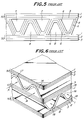
- Fig. 5 is a partial front elevation illustrating one example of such a solid oxide fuel cell.
- This SOFC is of a monolithic design referred to as "Co-flow model" of Argonne type first proposed by Argonne National Laboratory.
- a number of air electrode films 6, which nave an inverted V-shaped section, are provided in opposition to the flat plate-like air electrode films 1 to form a number of oxidizing gas flow passages 8 in a direction orthogonal to the paper.
- These fuel gas flow passages 7 and the oxidizing gas flow passages 8 are combined with one another in the form of a mosaic, and a wavy solid electrolyte film 5 is formed between the fuel electrode films 4 and the air electrode films 6.
- a wavy solid electrolyte film 5 is formed between the fuel electrode films 4 and the air electrode films 6.
- the power generation is performed among these films.
- the films are shown only in one row for the sake of simplicity in Fig. 5, a number of the laminates shown in Fig. 5 are piled one upon another to form a number of gas flow passages in the form of a honeycomb.
- Fig. 6 illustrates a SOFC of the Argonne type which is similar to that of Fig. 5, but referred to as "Cross flow model”.
- This SOFC is composed of flat plate-like laminates 50 and 51 alternately laminated.
- the former laminate 50 is similar to that shown in Fig. 5, and the laminate 51 is formed by arranging successively a flat plate-like fuel electrode film 3, a flat plate-like solid electrolyte film 15 and a flat plate-like air electrode film 1 arranged in parallel with one another with a predetermined interval.
- a wavy fuel electrode film 14 In each space between the two flat plate-like fuel electrode films 3 is arranged a wavy fuel electrode film 14 to form fuel gas flow passages 17 into which a fuel gas is supplied as shown by arrows A.
- a wavy air electrode film 16 to form oxidizing gas flow passages 18 into which an oxidizing gas is supplied as shown by arrows B.
- the fuel gas flow passage 17 and the oxidizing gas flow passage 18 are crossed by a predetermined angle, for example, 90°.
- the flat plate-like fuel electrode film 3 there are interposed the flat plate-like solid electrolyte film 15 and the flat plate-like air electrode film 1 in this order. The power generation is performed in these interposed films.
- the present invention is to provide the solid oxide fuel cell comprising a plurality of flat plate-like laminates spaced substantially in parallel with one another, each of the laminates having one surface covered with a flat plate-like air electrode film and the other surface covered with a flat plate-like fuel electrode film, a plurality of oxidizing gas flow passages arranged between the adjacent flat plate-like laminates and facing the flat plate-like air electrode film, a plurality of fuel gas flow passages arranged between the adjacent flat plate-like laminates and facing the flat plate-like fuel electrode film, and at least air electrode films, solid electrolyte films and fuel electrode films interposed between the oxidizing gas flow passage and the adjacent fuel gas flow passage, wherein oxidizing gas supply pipes are each extended from one end opening of each of the oxidizing gas flow passages into the interior thereof to feed oxidizing gas into the oxidizing gas flow passage so that the oxidizing gas flows back along the passage in contact with the air electrode films, closure members each close the other end of each of the oxidizing gas
- the "air electrode films” are identical with or different from the “flat plate-like air electrode films", and further the “fuel electrode films” are identical with or different from the “flat plate-like fuel electrode films”.
- the "solid electrolyte film” is located between the flat plate-like air electrode film and the flat plate-like fuel electrode film, and constitutes a part of the "flat plate-like laminates".
- the "solid electrolyte film” does not constitute a part of the "flat plate-like laminate", but is located between the adjacent flat plate-like laminates.
- Fig. 1 is a perspective view of the SOFC according to an embodiment of the present invention, snowing only part of one layer in an enlarged scale for the sake of convenience in explanation.
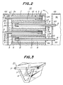
- Fig. 2 is a partial sectional view of this SOFC.
- a fuel gas supply pipe 10 is provided extending from an opening 7a at one end (on the side of a viewer in Fig. 1 and on the left side of Fig. 2) of each of fuel gas flow passages 7 to the other end thereof.
- the fuel gas supply pipe 10 is supported by three radial ribs 11 in this embodiment. The number of the ribs 11 is of course arbitrary.
- a closure member 24 is provided at the other end of each of the fuel gas flow passages 7 having the fuel gas supply pipe 10 inserted therein, and prevents the fuel gas from escaping therefrom.
- a base portion of the fuel gas supply pipe 10 is exposed in a fuel gas supply chamber 34 defined by a partition wall 64, and a forward end of the fuel gas supply pipe 10 is fixed close to the closure member 24.
- an oxidizing gas supply pipe 20 is provided extending from an opening 8a at one end of each of the oxidizing gas flow passages 8 toward the other end, and supported by three radial ribs 11.
- a closure member 26 is provided at the other end of the oxidizing gas flow passage 8 having the oxidizing gas supply pipe 20 inserted thereinto, and prevents the oxidizing gas from escaping.
- a base portion of the oxidizing gas supply pipe 20 is exposed in an oxidizing gas supply chamber 36 defined by a partition wall 66, and a forward end of the oxidizing gas supply pipe 20 is fixed close to the closure member 26.
- an oxidizing gas is supplied from the oxidizing gas supply chamber 36 into the oxidizing supply pipes 20 as shown by arrows B.
- the oxidizing gas leaves the forward ends of the oxidizing gas supply pipe 20 and is turned at the closure member in the reverse directions.
- the oxidizing gas then flows between the oxidizing gas supply pipe 20 and the air electrode 6, and leaves the end opening 8a as shown by arrows D.
- This fuel cell is so designed that the oxidizing gas is caused to flow by pressure difference between the exhaust gas combustion chamber 30 and the oxidizing gas supply chamber 36.
- the used oxidizing gas whose concentration has been lowered owing to utilization for the generation of the electric power is thus caused to flow into the exhaust gas combustion chamber 30.
- An interconnector 2 is provided between the flat plate-like fuel electrode film 3 and the flat plate-like air electrode film 1 to connect respective layers in series. Finally, a load is connected between upper and lower ends of the stack to extract electric power.
- the air electrode films 1 and 6 may be made of LaMnO3, CaMnO3, LaNiO3, LaCoO3, LaCrO3 or the like doped or not doped. Among them, LaMnO3 doped with strontium is preferred.
- the solid electrolyte films 5 may be generally made of yttria-stabilized zirconia or the like.
- the fuel electrode films 3 and 4 are preferably made of nickel-zirconia cermet or cobalt-zirconia cermet.
- the fuel gas supply pipes 10, the ribs 11 and the closure members 24 may be made of materials different from that of the fuel electrode films 3 and 4 surrounding them, but are preferably made of the same material as that of the electrodes 3 and 4 as described later.
- the oxidizing gas supply pipes 20, the ribs supporting them and the closure members 26 may also be made of materials different from that of the air electrode films 1 and 6, but are preferably made of the same material as that of the latter.
- the SOFC according to this embodiment brings about the following effects.
- the fuel gas and the oxidizing gas can be certainly fed into the entire gas flow passages 7 and 8 with high efficiency by combining the fuel gas supply pipes 10 and the oxidizing gas supply pipes 20 with the closure members 24 and 26 of the gas flow passages provided at the proximity of the open ends of the relevant supply pipes. Consequently, this arrangement solves the problems arising with the supply of the fuel gas and the oxidizing gas into the Argonne type SOFC whose power generating efficiency is high. As a result of this, the practical applicability is enhanced.
- blocks forming the gas flow passages 7 and 8, respectively are produced separately, and then combined together.
- a fuel electrode material is extruded to form blocks 31 each comprising a flat plate-like fuel electrode film 3, a fuel electrode film 4 having a substantially V-shaped section, three ribs 11 and a fuel gas supply pipe 10. Thereafter, these blocks are fired.
- An air electrode material is also extruded to obtain similar blocks for air electrodes.
- the blocks thus produced are successively combined in a mosaic-like fashion with solid electrolyte films 5 and interconnectors 2 to obtain the arrangement shown in Fig. 1.
- the blocks may be individually fired and then combined, or the blocks may be combined on shaping and then fired.
- Fig. 4 is a partially cut-away perspective view illustrating an embodiment which is an application of the present invention to the Argonne type cross flow model.
- each of the fuel gas flow passages is provided with a fuel gas supply pipe (not shown) and each of the oxidizing gas flow passages 18 is provided with an oxidizing gas supply pipe 20.
- These gas supply pipes are each supported by three ribs 11, respectively, in the same manner as in the SOFC shown in Fig. 1.
- each of the gas flow passages is provided with a closure member 44 at the other end (on the side of the fuel gas flow passage) to prevent the gas from flowing out therefrom.
- similar closure members 44 are of course provided for the oxidizing gas flow passages (not shown).
- the oxidizing gas is supplied into the oxidizing gas supply pipes 20 shown by an arrow B.
- the gas When the oxidizing gas arrives at the closure member (not shown), the gas is turned in the reverse direction so that the oxidizing gas used for generating power with the electrode reaction is emitted through the open end 18a shown by an arrow D.
- the fuel gas also flows and is then omitted through the fuel gas flow passage in the same manner as the oxidizing gas.
- one gas flow passage may be provided with plural fuel gas supply pipes or oxidizing gas supply pipes, respectively.
- these gas supply pipes may be provided with openings on the midway so that the fuel gas or the oxidizing gas is partially emitted through the openings.
- the entire solid oxide fuel cell may be vertically arranged, although horizontally fixed in Figs. 1 and 4.
- the fuel gas flow passages and the oxidizing gas flow passages intersect with each other at a predetermined angle in the prior art as indicated by its name. In the application of the present invention, however, it is not necessary to make them intersect with each other.
- the fuel gas and the oxidizing gas may be flown in the reverse directions as shown in Fig. 1 or in the same direction.
- the oxidizing gas supply pipe is provided in the oxidizing gas flow passage, and this passage has a closed end on the side opposites to the insertion side.
- the fuel gas supply pipe is provided in the fuel gas flow passage, and this pipe also has a closed end on the side opposite to the insertion side. Therefore, the gas supplied into the oxidizing gas supply pipe or the fuel gas supply pipe is interrupted and turned by the closed end of the supply pipe in the reverse direction so that the oxidizing gas or the fuel gas having the concentrations lowered owing to the electrode reaction is exhausted from the open end of the oxidizing gas flow passage or the fuel gas flow pipe.
- the oxidizing gas and the fuel gas can be supplied into the oxidizing gas flow passage and the fuel gas flow passage, respectively, with a great certainty. Consequently, with the solid oxide fuel cell including a plurality of the oxidizing gas flow passages and the fuel gas flow passages formed between the flat plate-like laminates and operating with high electric power generating efficiency, it is possible to solve the problems arising in the case of the supply of the fuel gas and the oxidizing gas and the exhaustion of the reacted gases to enhance the practical applicability of the fuel cell.
- the fuel cell according to the invention is high in reliability as a structural body.
Landscapes
- Life Sciences & Earth Sciences (AREA)
- Engineering & Computer Science (AREA)
- Manufacturing & Machinery (AREA)
- Sustainable Development (AREA)
- Sustainable Energy (AREA)
- Chemical & Material Sciences (AREA)
- Chemical Kinetics & Catalysis (AREA)
- Electrochemistry (AREA)
- General Chemical & Material Sciences (AREA)
- Fuel Cell (AREA)
Claims (9)
- Pile à combustible à oxyde solide comprenant plusieurs stratifiés (50) en forme de plaque plate écartés les uns des autres et disposés essentiellement parallèles les uns aux autres, chacun des stratifiés ayant une surface recouverte par un film d'électrode à air plat (1) et l'autre surface recouverte par un film d'électrode à combustible plat (3), plusieurs passages (8) pour l'écoulement du gaz oxydant étant disposés entre une paire voisine des dits stratifiés (50) et opposés à l'un des dits films d'électrode à air (1), plusieurs passages (7) pour l'écoulement du gaz combustible étant disposés entre une paire voisine des dits stratifiés plats (50) et opposés à l'un des dits films d'électrode à combustible, et au moins des films d'électrode à air (6), des films d'électrolyte solide (5) et des films d'électrode à combustible (4) étant interposés entre les dits passages (8) pour l'écoulement du gaz oxydant et les dits passages (7) pour l'écoulement du gaz combustible, dans laquelle un tuyau d'alimentation de gaz oxydant (20) est disposé depuis une ouverture à une extrémité de chacun des dits passages (8) pour l'écoulement des gaz oxydant dans le passage (8) pour l'écoulement des gaz oxydant, si bien que le gaz oxydant revient par le passage (8) en contact avec les films d'électrode à air (1,6) et des fermetures d'élément (26) sont disposées pour fermer les autres extrémités correspondantes des passages pour l'écoulement du gaz oxydant, caractérisé en ce que un tuyau d'alimentation de gaz combustible (10) est disposé depuis une ouverture à une extrémité de chacun desdits passages (7) pour l'écoulement de gaz combustible dans le passage pour l'écoulement de gaz combustible pour amener le gaz combustible dans le passage (7) pour l'écoulement du gaz combustible, si bien que le gaz combustible revient par le passage (7) en contact avec le film d'électrode à combustible (3,4), et que des éléments de fermeture (24) sont disposés pour fermer les autres extrémités correspondantes des passages pour l'écoulement du gaz combustible.
- Pile à combustible à oxyde solide selon la revendication 1, dans laquelle lesdits tuyaux d'alimentation de gaz oxydant (20) sont supportés par les nervures radiales (11) sur les parois délimitant les passages (8) pour l'écoulement du gaz oxydant et dans laquelle lesdits tuyaux (10) pour l'alimentation de gaz combustible sont supportés par des nervures radiales (11) sur les parois délimitant les passages (7) pour l'écoulement de gaz combustible.
- Pile à combustible à oxyde solide selon la revendication 2, dans laquelle lesdits tuyaux (10) pour l'alimentation des gaz combustibles, lesdites nervures (11) supportant lesdits tuyaux (10) pour l'alimentation de gaz combustible et lesdits éléments de fermeture (24) desdits passages (7) pour l'écoulement du gaz combustible sont réalisés dans le même matériau que celui des films d'électrode à combustible (3,4) qui les entourent.
- Pile à combustible à oxyde solide selon la revendication 2 ou la revendication 3, dans laquelle lesdits tuyaux 20 pour l'alimentation de gaz oxydant, lesdites nervures (11) supportant lesdits tuyaux d'alimentation de gaz d'oxygène et lesdits éléments de fermeture (26) desdits passages (8) pour l'écoulement du gaz oxydant sont réalisés avec le même matériau que celui des films d'électrode à air (1,6).
- Pile à combustible à oxyde solide selon l'une quelconque des revendications 1 à 4, dans laquelle une partie de base de chacun des tuyaux (20) pour l'alimentation des gaz oxydants débouche dans une chambre (36) pour l'alimentation de gaz oxydant et une extrémité avant du tuyau d'alimentation de gaz oxydant est située près de l'élément de fermeture correspondant (26) et une partie de base de chacun des tuyaux (10) pour l'alimentation de gaz combustible débouche dans une chambre (34) pour l'alimentation de gaz combustible et une extrémité avant de chacun des tuyaux d'alimentation de gaz oxydant est située près de l'élément de fermeture correspondant (24).
- Pile à combustible à oxyde solide selon l'une quelconque des revendications 1 à 5, dans laquelle lesdits films d'électrode à air (1,6) sont constitués d'un matériau choisi parmi LaMnO₃, CaMnO₃, LaNiO₃, LaCoO₃ et LaCrO₃.
- Pile à combustible à oxyde solide selon la revendication 6 dans laquelle lesdits films d'électrode à air (1,6) sont constitué de LaMnO₃ dopé par le strontium.
- Pile à combustible à oxyde solide selon l'une quelconque des revendications 1 à 7, dans laquelle lesdits films d'électrode solide (5) sont constitués d'oxyde de zirconium stabilisé par l'yttrium.
- Pile à combustible à oxyde solide selon l'une quelconque des revendications 1 à 8, dans laquelle lesdits films d'électrode à combustible (3,4) sont constitués d'un matériau choisi parmi le cermet d'oxyde de zirconium nickel et le cermet d'oxyde de zirconium cobalt.
Applications Claiming Priority (2)
| Application Number | Priority Date | Filing Date | Title |
|---|---|---|---|
| JP32382/90 | 1990-02-15 | ||
| JP2032382A JP2528987B2 (ja) | 1990-02-15 | 1990-02-15 | 固体電解質型燃料電池 |
Publications (2)
| Publication Number | Publication Date |
|---|---|
| EP0442741A1 EP0442741A1 (fr) | 1991-08-21 |
| EP0442741B1 true EP0442741B1 (fr) | 1995-05-03 |
Family
ID=12357405
Family Applications (1)
| Application Number | Title | Priority Date | Filing Date |
|---|---|---|---|
| EP91301209A Expired - Lifetime EP0442741B1 (fr) | 1990-02-15 | 1991-02-14 | Pile à combustible d'oxyde solide |
Country Status (5)
| Country | Link |
|---|---|
| US (1) | US5145754A (fr) |
| EP (1) | EP0442741B1 (fr) |
| JP (1) | JP2528987B2 (fr) |
| CA (1) | CA2036252C (fr) |
| DE (1) | DE69109335T2 (fr) |
Families Citing this family (27)
| Publication number | Priority date | Publication date | Assignee | Title |
|---|---|---|---|---|
| JPH04292865A (ja) * | 1991-03-20 | 1992-10-16 | Ngk Insulators Ltd | 固体電解質型燃料電池 |
| US5292599A (en) * | 1991-09-27 | 1994-03-08 | Ngk Insulators, Ltd. | Cell units for solid oxide fuel cells and power generators using such cell units |
| US5273837A (en) * | 1992-12-23 | 1993-12-28 | Corning Incorporated | Solid electrolyte fuel cells |
| US5424144A (en) * | 1993-10-21 | 1995-06-13 | M-C Power Corporation | One piece separator plate with insert ring step design |
| GB9403234D0 (en) * | 1994-02-19 | 1994-04-13 | Rolls Royce Plc | A solid oxide fuel cell stack and a reactant distribution member therefor |
| US5763114A (en) * | 1994-09-01 | 1998-06-09 | Gas Research Institute | Integrated reformer/CPN SOFC stack module design |
| JPH08130023A (ja) * | 1994-10-27 | 1996-05-21 | Aisin Seiki Co Ltd | 燃料電池 |
| JP3215650B2 (ja) | 1996-05-23 | 2001-10-09 | 日本碍子株式会社 | 電気化学セル、その製造方法および電気化学装置 |
| EP0840388B1 (fr) * | 1996-10-30 | 2005-08-24 | Sulzer Hexis AG | Batterie de piles à combustible de type plan fonctionnant à haute température |
| US5770326A (en) * | 1996-12-23 | 1998-06-23 | Limaye; Santosh Y. | Monolithic mass and energy transfer cell |
| US5976721A (en) * | 1997-09-15 | 1999-11-02 | Limaye; Santosh Y. | Chemical cogeneration process |
| US6372375B1 (en) * | 1998-06-12 | 2002-04-16 | Ceramphysics, Inc. | Ceramic fuel cell |
| GB9814121D0 (en) * | 1998-07-01 | 1998-08-26 | British Gas Plc | Separator plate for the use in a fuel cell stack |
| US6224993B1 (en) * | 1998-10-21 | 2001-05-01 | Sofco | Electrolyte for solid oxide fuel cells |
| US6368739B1 (en) * | 1999-09-08 | 2002-04-09 | Sofco | Joined solid oxide fuel cell stacks and method for fabricating same |
| JP2001357860A (ja) * | 2000-06-14 | 2001-12-26 | Mitsubishi Heavy Ind Ltd | 燃料電池装置および燃料電池の冷却方法 |
| WO2003028132A1 (fr) * | 2000-06-14 | 2003-04-03 | Mitsubishi Heavy Industries, Ltd. | Dispositif de pile a combustible et procede de refroidissement de pile a combustible |
| US6677069B1 (en) | 2000-08-18 | 2004-01-13 | Hybrid Power Generation Systems, Llc | Sealless radial solid oxide fuel cell stack design |
| SE521952C2 (sv) | 2000-09-19 | 2003-12-23 | Volvo Teknisk Utveckling Ab | Bränslecellsenhet samt bränslecellsanordning innefattande ett flertal sådana bränslecellsenheter |
| AU2002337635A1 (en) * | 2001-01-05 | 2003-01-21 | Georgia Tech Research Corporation | Hybrid monolithic fuel cell |
| DE10229820B4 (de) * | 2002-06-28 | 2004-12-30 | Deutsches Zentrum für Luft- und Raumfahrt e.V. | Gasverteilungsvorrichtung für eine elektrochemische Elektrode und Verfahren zur Reaktionsgasbeaufschlagung einer elektrochemischen Elektrode |
| EP1662598A4 (fr) * | 2003-06-30 | 2010-08-11 | Japan Energy Corp | Pile a combustible avec dispositif de reformage |
| US7816055B2 (en) * | 2004-03-16 | 2010-10-19 | The Regents Of The University Of California | Compact fuel cell |
| JP4965066B2 (ja) * | 2004-08-19 | 2012-07-04 | 株式会社日立製作所 | 燃料電池 |
| WO2007005767A1 (fr) * | 2005-07-01 | 2007-01-11 | The Regents Of The University Of California | Conception de pile a combustibles a oxyde solide avancee pour generation electrique |
| CN102047481B (zh) * | 2008-05-30 | 2013-09-25 | 康宁股份有限公司 | 固体氧化物燃料电池系统 |
| NL2002113C (nl) * | 2008-10-20 | 2010-04-21 | Stichting Energie | Sofc-stack met gegolfde separatorplaat. |
Family Cites Families (8)
| Publication number | Priority date | Publication date | Assignee | Title |
|---|---|---|---|---|
| US4374184A (en) * | 1981-09-29 | 1983-02-15 | Westinghouse Electric Corp. | Fuel cell generator and method of operating same |
| US4499663A (en) * | 1983-10-12 | 1985-02-19 | The United States Of America As Represented By The United States Department Of Energy | Method of fabricating a monolithic core for a solid oxide fuel cell |
| US4476198A (en) * | 1983-10-12 | 1984-10-09 | The United States Of America As Represented By The United States Department Of Energy | Solid oxide fuel cell having monolithic core |
| US4476197A (en) * | 1983-10-12 | 1984-10-09 | The United States Of America As Represented By The United States Department Of Energy | Integral manifolding structure for fuel cell core having parallel gas flow |
| JPS63207054A (ja) * | 1987-02-23 | 1988-08-26 | Fujikura Ltd | 固体電解質燃料電池発電装置 |
| US4751152A (en) * | 1987-04-06 | 1988-06-14 | Westinghouse Electric Corp. | High bulk self-supporting electrode with integral gas feed conduit for solid oxide fuel cells |
| JPH01124964A (ja) * | 1987-11-10 | 1989-05-17 | Mitsubishi Heavy Ind Ltd | 平板型固体電解質燃料電池 |
| US4883497A (en) * | 1988-03-28 | 1989-11-28 | Arch Development Corporation | Formation of thin walled ceramic solid oxide fuel cells |
-
1990
- 1990-02-15 JP JP2032382A patent/JP2528987B2/ja not_active Expired - Lifetime
-
1991
- 1991-02-07 US US07/651,973 patent/US5145754A/en not_active Expired - Fee Related
- 1991-02-13 CA CA002036252A patent/CA2036252C/fr not_active Expired - Fee Related
- 1991-02-14 DE DE69109335T patent/DE69109335T2/de not_active Expired - Fee Related
- 1991-02-14 EP EP91301209A patent/EP0442741B1/fr not_active Expired - Lifetime
Also Published As
| Publication number | Publication date |
|---|---|
| JP2528987B2 (ja) | 1996-08-28 |
| CA2036252C (fr) | 1994-07-26 |
| EP0442741A1 (fr) | 1991-08-21 |
| US5145754A (en) | 1992-09-08 |
| DE69109335T2 (de) | 1996-01-25 |
| JPH03238762A (ja) | 1991-10-24 |
| CA2036252A1 (fr) | 1991-08-16 |
| DE69109335D1 (de) | 1995-06-08 |
Similar Documents
| Publication | Publication Date | Title |
|---|---|---|
| EP0442741B1 (fr) | Pile à combustible d'oxyde solide | |
| US5185219A (en) | Solid oxide fuel cells | |
| US4476196A (en) | Solid oxide fuel cell having monolithic cross flow core and manifolding | |
| US4476197A (en) | Integral manifolding structure for fuel cell core having parallel gas flow | |
| US4943494A (en) | Solid oxide fuel cell matrix and modules | |
| CA2063518C (fr) | Pile a combustible a electrolyte solide | |
| US5733675A (en) | Electrochemical fuel cell generator having an internal and leak tight hydrocarbon fuel reformer | |
| US4510212A (en) | Solid oxide fuel cell having compound cross flow gas patterns | |
| US4666798A (en) | Serially connected solid oxide fuel cells having monolithic cores | |
| EP0055016B1 (fr) | Arrangements de piles à combustible à électrolyte solide fonctionnant à haute température | |
| EP0355420A1 (fr) | Pile à combustible à électrolyte solide | |
| EP0740358B1 (fr) | Unités de cellule pour piles à combustible à oxydes solides et générateur d'énergie utilisant ces unités de cellule | |
| US7947386B2 (en) | Solid oxide fuel cell module, fuel cell system using the same and manufacturing method thereof | |
| US20060051641A1 (en) | Honeycomb type solid electrolytic fuel cell | |
| KR102872147B1 (ko) | 전기 화학 소자, 전기 화학 모듈, 전기 화학 장치 및 에너지 시스템 | |
| JPH04237962A (ja) | 平板型固体電解質燃料電池 | |
| KR102905930B1 (ko) | 고체산화물 연료전지와 고체산화물 전해셀 | |
| US8021794B2 (en) | Fuel cell with cross-shaped reformer | |
| EP1970988A1 (fr) | Pile a combustible | |
| JPH03219563A (ja) | 固体電解質型燃料電池 | |
| US4824742A (en) | Manifold, bus support and coupling arrangement for solid oxide fuel cells | |
| US20050282051A1 (en) | Integrated honeycomb solid electrolyte fuel cells | |
| JP2009087550A (ja) | 固体酸化物形燃料電池 | |
| JP4300947B2 (ja) | 固体酸化物形燃料電池 | |
| JP4814497B2 (ja) | 燃料電池 |
Legal Events
| Date | Code | Title | Description |
|---|---|---|---|
| PUAI | Public reference made under article 153(3) epc to a published international application that has entered the european phase |
Free format text: ORIGINAL CODE: 0009012 |
|
| AK | Designated contracting states |
Kind code of ref document: A1 Designated state(s): BE DE FR GB |
|
| 17P | Request for examination filed |
Effective date: 19920211 |
|
| 17Q | First examination report despatched |
Effective date: 19940520 |
|
| GRAA | (expected) grant |
Free format text: ORIGINAL CODE: 0009210 |
|
| AK | Designated contracting states |
Kind code of ref document: B1 Designated state(s): BE DE FR GB |
|
| REF | Corresponds to: |
Ref document number: 69109335 Country of ref document: DE Date of ref document: 19950608 |
|
| ET | Fr: translation filed | ||
| PLBE | No opposition filed within time limit |
Free format text: ORIGINAL CODE: 0009261 |
|
| STAA | Information on the status of an ep patent application or granted ep patent |
Free format text: STATUS: NO OPPOSITION FILED WITHIN TIME LIMIT |
|
| 26N | No opposition filed | ||
| PGFP | Annual fee paid to national office [announced via postgrant information from national office to epo] |
Ref country code: GB Payment date: 19980204 Year of fee payment: 8 |
|
| PGFP | Annual fee paid to national office [announced via postgrant information from national office to epo] |
Ref country code: FR Payment date: 19980213 Year of fee payment: 8 |
|
| PGFP | Annual fee paid to national office [announced via postgrant information from national office to epo] |
Ref country code: DE Payment date: 19980217 Year of fee payment: 8 |
|
| PGFP | Annual fee paid to national office [announced via postgrant information from national office to epo] |
Ref country code: BE Payment date: 19980218 Year of fee payment: 8 |
|
| PG25 | Lapsed in a contracting state [announced via postgrant information from national office to epo] |
Ref country code: GB Free format text: LAPSE BECAUSE OF NON-PAYMENT OF DUE FEES Effective date: 19990214 |
|
| PG25 | Lapsed in a contracting state [announced via postgrant information from national office to epo] |
Ref country code: BE Free format text: LAPSE BECAUSE OF NON-PAYMENT OF DUE FEES Effective date: 19990228 |
|
| BERE | Be: lapsed |
Owner name: NGK INSULATORS LTD Effective date: 19990228 |
|
| GBPC | Gb: european patent ceased through non-payment of renewal fee |
Effective date: 19990214 |
|
| PG25 | Lapsed in a contracting state [announced via postgrant information from national office to epo] |
Ref country code: FR Free format text: LAPSE BECAUSE OF NON-PAYMENT OF DUE FEES Effective date: 19991029 |
|
| PG25 | Lapsed in a contracting state [announced via postgrant information from national office to epo] |
Ref country code: DE Free format text: LAPSE BECAUSE OF NON-PAYMENT OF DUE FEES Effective date: 19991201 |
|
| REG | Reference to a national code |
Ref country code: FR Ref legal event code: ST |