EP0442789B1 - Remote control system, particularly to lock/unlock car doors - Google Patents
Remote control system, particularly to lock/unlock car doors Download PDFInfo
- Publication number
- EP0442789B1 EP0442789B1 EP91400314A EP91400314A EP0442789B1 EP 0442789 B1 EP0442789 B1 EP 0442789B1 EP 91400314 A EP91400314 A EP 91400314A EP 91400314 A EP91400314 A EP 91400314A EP 0442789 B1 EP0442789 B1 EP 0442789B1
- Authority
- EP
- European Patent Office
- Prior art keywords
- remote control
- light source
- control system
- light
- doors
- Prior art date
- Legal status (The legal status is an assumption and is not a legal conclusion. Google has not performed a legal analysis and makes no representation as to the accuracy of the status listed.)
- Expired - Lifetime
Links
Images
Classifications
-
- H—ELECTRICITY
- H10—SEMICONDUCTOR DEVICES; ELECTRIC SOLID-STATE DEVICES NOT OTHERWISE PROVIDED FOR
- H10H—INORGANIC LIGHT-EMITTING SEMICONDUCTOR DEVICES HAVING POTENTIAL BARRIERS
- H10H20/00—Individual inorganic light-emitting semiconductor devices having potential barriers, e.g. light-emitting diodes [LED]
- H10H20/80—Constructional details
- H10H20/85—Packages
- H10H20/852—Encapsulations
- H10H20/853—Encapsulations characterised by their shape
-
- G—PHYSICS
- G07—CHECKING-DEVICES
- G07C—TIME OR ATTENDANCE REGISTERS; REGISTERING OR INDICATING THE WORKING OF MACHINES; GENERATING RANDOM NUMBERS; VOTING OR LOTTERY APPARATUS; ARRANGEMENTS, SYSTEMS OR APPARATUS FOR CHECKING NOT PROVIDED FOR ELSEWHERE
- G07C9/00—Individual registration on entry or exit
- G07C9/00174—Electronically operated locks; Circuits therefor; Nonmechanical keys therefor, e.g. passive or active electrical keys or other data carriers without mechanical keys
- G07C9/00182—Electronically operated locks; Circuits therefor; Nonmechanical keys therefor, e.g. passive or active electrical keys or other data carriers without mechanical keys operated with unidirectional data transmission between data carrier and locks
-
- G—PHYSICS
- G07—CHECKING-DEVICES
- G07C—TIME OR ATTENDANCE REGISTERS; REGISTERING OR INDICATING THE WORKING OF MACHINES; GENERATING RANDOM NUMBERS; VOTING OR LOTTERY APPARATUS; ARRANGEMENTS, SYSTEMS OR APPARATUS FOR CHECKING NOT PROVIDED FOR ELSEWHERE
- G07C9/00—Individual registration on entry or exit
- G07C9/00174—Electronically operated locks; Circuits therefor; Nonmechanical keys therefor, e.g. passive or active electrical keys or other data carriers without mechanical keys
- G07C9/00182—Electronically operated locks; Circuits therefor; Nonmechanical keys therefor, e.g. passive or active electrical keys or other data carriers without mechanical keys operated with unidirectional data transmission between data carrier and locks
- G07C2009/00198—Electronically operated locks; Circuits therefor; Nonmechanical keys therefor, e.g. passive or active electrical keys or other data carriers without mechanical keys operated with unidirectional data transmission between data carrier and locks the keyless data carrier having more than one limited data transmission ranges
-
- G—PHYSICS
- G07—CHECKING-DEVICES
- G07C—TIME OR ATTENDANCE REGISTERS; REGISTERING OR INDICATING THE WORKING OF MACHINES; GENERATING RANDOM NUMBERS; VOTING OR LOTTERY APPARATUS; ARRANGEMENTS, SYSTEMS OR APPARATUS FOR CHECKING NOT PROVIDED FOR ELSEWHERE
- G07C9/00—Individual registration on entry or exit
- G07C9/00174—Electronically operated locks; Circuits therefor; Nonmechanical keys therefor, e.g. passive or active electrical keys or other data carriers without mechanical keys
- G07C2009/00753—Electronically operated locks; Circuits therefor; Nonmechanical keys therefor, e.g. passive or active electrical keys or other data carriers without mechanical keys operated by active electrical keys
- G07C2009/00769—Electronically operated locks; Circuits therefor; Nonmechanical keys therefor, e.g. passive or active electrical keys or other data carriers without mechanical keys operated by active electrical keys with data transmission performed by wireless means
- G07C2009/00785—Electronically operated locks; Circuits therefor; Nonmechanical keys therefor, e.g. passive or active electrical keys or other data carriers without mechanical keys operated by active electrical keys with data transmission performed by wireless means by light
-
- H—ELECTRICITY
- H10—SEMICONDUCTOR DEVICES; ELECTRIC SOLID-STATE DEVICES NOT OTHERWISE PROVIDED FOR
- H10H—INORGANIC LIGHT-EMITTING SEMICONDUCTOR DEVICES HAVING POTENTIAL BARRIERS
- H10H20/00—Individual inorganic light-emitting semiconductor devices having potential barriers, e.g. light-emitting diodes [LED]
- H10H20/80—Constructional details
- H10H20/85—Packages
- H10H20/857—Interconnections, e.g. lead-frames, bond wires or solder balls
-
- H—ELECTRICITY
- H10—SEMICONDUCTOR DEVICES; ELECTRIC SOLID-STATE DEVICES NOT OTHERWISE PROVIDED FOR
- H10W—GENERIC PACKAGES, INTERCONNECTIONS, CONNECTORS OR OTHER CONSTRUCTIONAL DETAILS OF DEVICES COVERED BY CLASS H10
- H10W90/00—Package configurations
Definitions
- the present invention relates to the field of remote control systems, in particular for infrared link.
- the present invention is particularly applicable to remote control systems for locking and unlocking doors of motor vehicles.
- Known remote control systems generally include, at the level of the transmitter, light source means capable of generating a coded light flux, associated with optical means suitable for configuring the beam generated by the light source.
- the document FR-A-2352313 describes an optic intended for the transformation of the emission diagram of a light source. More specifically, the aim of this optic is to transform the multidirectional emission diagram of a light source located substantially in the middle region of its basic plane into a diagram with relatively high axial intensity.
- the optics considered from its apex to its base plane, be limited, at least partially, by a spherical cap whose center of curvature is located between said apex and said source, that extends without detachment at least one spherical zone whose center of curvature is located between that of said spherical cap and said source.
- This optic can in particular find application in a remote control assembly, in particular of a television receiver. Indeed, according to this document, thanks to this optic, if the control at maximum range (on the axis) remains directive, the control at medium and short distance becomes much more flexible, the lateral light intensity then being sufficient to ensure the desired command.
- the main object of the present invention is to propose new means making it possible to optimize the range of the transmitter.
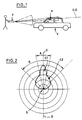
- FIG. 1 There is schematically shown in Figure 1 attached, a remote control system according to the present invention designed to lock / unlock a remote motor vehicle V.
- This system comprises a transmitter E and a receiver R.
- the transmitter E is placed in a portable box. It is designed to generate a coded electromagnetic wave, most often infrared radiation.
- the receiver R is placed in the vehicle V. It is designed to receive and decode the signal generated by the transmitter E.
- the receiver R controls the locking / unlocking of the doors of the motor vehicle respectively.
- the direction axis of the transmitter has been referenced O-O. Furthermore, in FIG. 2, the light source placed in the center of the diagram is referenced S.
- FIG. 2 represents the emission lobe in an axial plane, that is to say passing through the director axis O-O.
- the emission lobe is symmetrical in revolution around this O-O direction axis.
- the emission lobe according to the invention is formed of two components C1, C2.
- the first component C1 centered on the director axis OO has a large range but a relatively small opening angle A.
- the second component C2 which surrounds the first component C1 and is also centered on the director axis OO has a smaller range than the first component but a greater opening angle. This angle upper opening is referenced B in Figure 2.
- the first component C1 has an angular opening A of the order of 30 °, more or less 15 ° on either side of the director axis O-O.
- the second component C2 has a greater angular opening B of the order of 90 °, or more or less 45 ° on either side of the director axis OO, but a range of 2 to 2.5 times less than the first component C1.
- the light source and the associated optical configuration means preferably take the form of light-emitting diodes in the infrared range.
- the crystal is embedded in a mass of transparent plastic. It may for example be polymethylmethacrylate PMMA.
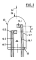
- FIG. 3 shows an embodiment of a photo-emissive diode according to the present invention.
- the front face of the body of the diode is delimited by a single spherical cap 29 centered on a point passing through the axis 24.
- two electroluminescent crystals 10.1, 10.2 are provided, associated respectively with pairs of d '' electrodes 12.1, 14.1 and 12.2. and 14.2.
- the crystals 10.1, 10.2 are both placed in the vicinity of the axis 24, preferably respectively on either side of it. Furthermore, the crystals 10.1 and 10.2 are offset axially by a distance d.
- the cooperation of the foremost crystal 10.1 and the front face 29 of the diode makes it possible to define the first component C1 of the emission lobe.
- the cooperation of the second rearmost crystal 10.2 and the front surface 29 of the diode makes it possible to define the second component C2 of the emission lobe.
- the emissive part is formed by two juxtaposed diodes having different distances between their emitter crystal and the center of the respective spherical output surfaces.
Landscapes
- Engineering & Computer Science (AREA)
- Computer Networks & Wireless Communication (AREA)
- Physics & Mathematics (AREA)
- General Physics & Mathematics (AREA)
- Lock And Its Accessories (AREA)
- Arrangements For Transmission Of Measured Signals (AREA)
Description
La présente invention concerne le domaine des systèmes de télécommande, notamment pour liaison infrarouge.The present invention relates to the field of remote control systems, in particular for infrared link.
La présente invention s'applique tout particulièrement aux systèmes de télécommande pour le verrouillage et le déverrouillage de portières de véhicules automobiles.The present invention is particularly applicable to remote control systems for locking and unlocking doors of motor vehicles.
Les systèmes de télécommande connus comprennent généralement, au niveau de l'émetteur, des moyens formant source de lumière aptes à générer un flux lumineux codé, associés à des moyens optiques adaptés pour configurer le faisceau généré par la source de lumière.Known remote control systems generally include, at the level of the transmitter, light source means capable of generating a coded light flux, associated with optical means suitable for configuring the beam generated by the light source.
Le document PATENT ABSTRACTS OF JAPAN, vol. 8, n°66 (E-234) (1503), 25 Mars 1984 & JP-A-58216479, décrit une diode émettrice de lumière comprenant une lentille de sortie formée par la combinaison d'au moins deux sphères de rayons différents et de centres décalés, afin d'accroître l'intensité lumineuse axiale.The document PATENT ABSTRACTS OF JAPAN, vol. 8, n ° 66 (E-234) (1503), March 25, 1984 & JP-A-58216479, describes a light emitting diode comprising an output lens formed by the combination of at least two spheres of different radii and offset centers, in order to increase the axial light intensity.
Le document FR-A-2352313 décrit une optique destinée à la transformation du diagramme d'émission d'une source de lumière. Plus précisément, cette optique a pour but de transformer le diagramme d'émission pluridirectionnelle d'une source de lumière localisée sensiblement dans la région médiane de son plan de base en un diagramme à relativement forte intensité axiale. A cette fin, il est proposé dans ce document que l'optique, considérée depuis son sommet vers son plan de base, soit limitée, au moins partiellement, par une calotte sphérique dont le centre de courbure est situé entre ledit sommet et ladite source, que prolonge sans décrochement au moins une zone sphérique dont le centre de courbure est situé entre celui de ladite calotte sphérique et ladite source. Cette optique peut notamment trouver application dans un ensemble de commande à distance, notamment d'un récepteur de télévision. En effet, selon ce document, grâce à cette optique, si la commande à portée maximum (sur l'axe) demeure directive, la commande à moyenne et courte distance devient beaucoup plus souple, l'intensité lumineuse latérale pouvant alors suffir pour assurer la commande désirée.The document FR-A-2352313 describes an optic intended for the transformation of the emission diagram of a light source. More specifically, the aim of this optic is to transform the multidirectional emission diagram of a light source located substantially in the middle region of its basic plane into a diagram with relatively high axial intensity. To this end, it is proposed in this document that the optics, considered from its apex to its base plane, be limited, at least partially, by a spherical cap whose center of curvature is located between said apex and said source, that extends without detachment at least one spherical zone whose center of curvature is located between that of said spherical cap and said source. This optic can in particular find application in a remote control assembly, in particular of a television receiver. Indeed, according to this document, thanks to this optic, if the control at maximum range (on the axis) remains directive, the control at medium and short distance becomes much more flexible, the lateral light intensity then being sufficient to ensure the desired command.
La présente invention a pour but principal de proposer de nouveaux moyens permettant d'optimiser la portée de l'émetteur.The main object of the present invention is to propose new means making it possible to optimize the range of the transmitter.
La définition des systèmes de télécommande conformes à la présente invention, répondant au but précité, est donnée dans les revendications annexées.The definition of remote control systems in accordance with the present invention, fulfilling the above object, is given in the appended claims.
D'autres caractéristiques, buts et avantages de la présente invention apparaîtront à la lecture de la description détaillée qui va suivre, et en regard des dessins annexés, donnés à titre d'exemples non limitatifs et sur lesquels :
- la figure 1 représente schématiquement un système de télécommande pour le verrouillage/déverrouillage de portières de véhicules automobiles conforme à la présente invention,
- la figure 2 représente schématiquement le lobe d'émission de l'émetteur conforme à la présente invention dans un plan de coupe axial passant par l'axe directeur, et
- la figure 3, représente schématiquement, en coupe axiale, un mode de réalisation de moyen conforme à la présente invention.
- FIG. 1 schematically represents a remote control system for locking / unlocking the doors of motor vehicles according to the present invention,
- FIG. 2 schematically represents the emission lobe of the transmitter according to the present invention in an axial section plane passing through the director axis, and
- Figure 3 shows schematically, in axial section, an embodiment of means according to the present invention.
On a représenté schématiquement sur la figure 1 annexée, un système de télécommande conforme à la présente invention conçu pour assurer le verrouillage/déverrouillage à distance d'un véhicule automobile V. Ce système comprend un émetteur E et un récepteur R.There is schematically shown in Figure 1 attached, a remote control system according to the present invention designed to lock / unlock a remote motor vehicle V. This system comprises a transmitter E and a receiver R.
L'émetteur E est placé dans un boîtier portatif. Il est conçu pour générer une onde électromagnétique codée, le plus souvent un rayonnement infrarouge.The transmitter E is placed in a portable box. It is designed to generate a coded electromagnetic wave, most often infrared radiation.
Le récepteur R est placé dans le véhicule V. Il est conçu pour recevoir et décoder le signal généré par l'émetteur E.The receiver R is placed in the vehicle V. It is designed to receive and decode the signal generated by the transmitter E.
Lorsque le signal reçu par le récepteur R correspond à un code prédéterminé, le récepteur R contrôle le verrouillage/déverrouillage respectivement des portières du véhicule automobile.When the signal received by the receiver R corresponds to a predetermined code, the receiver R controls the locking / unlocking of the doors of the motor vehicle respectively.
De nombreux systèmes émetteurs et récepteurs ont déjà été proposés à cette fin.Many transmitter and receiver systems have already been proposed for this purpose.
Pour cette raison, la structure de l'émetteur E et du récepteur R ne sera pas décrite en détail par la suite.For this reason, the structure of the transmitter E and the receiver R will not be described in detail below.
Dans le cadre de la présente demande de brevet, on se contentera de décrire l'étage finale de l'émetteur E composé comme indiqué précédemment par une source de lumière associée à des moyens optiques de configuration.In the context of the present patent application, it will be sufficient to describe the final stage of the emitter E composed as indicated above by a light source associated with optical configuration means.
On a représenté schématiquement sur la figure 2 le lobe d'émission de l'émetteur E conforme à l'invention.Schematically shown in Figure 2 the emission lobe of the transmitter E according to the invention.
Sur la figure 2 on a référencé O-O l'axe directeur de l'émetteur. Par ailleurs, sur la figure 2, la source lumineuse placée au centre du diagramme est référencée S.In FIG. 2, the direction axis of the transmitter has been referenced O-O. Furthermore, in FIG. 2, the light source placed in the center of the diagram is referenced S.
Plus précisément la figure 2 représente le lobe d'émission dans un plan axial, c'est-à-dire passant par l'axe directeur O-O. En réalité, le lobe d'émission est symétrique de révolution autour de cet axe directeur O-O.More precisely, FIG. 2 represents the emission lobe in an axial plane, that is to say passing through the director axis O-O. In reality, the emission lobe is symmetrical in revolution around this O-O direction axis.
Sur la figure 2 les différents cercles concentriques, centrés sur la source S, représentent la portée de l'émetteur.In Figure 2 the different concentric circles, centered on the source S, represent the range of the transmitter.
Comme on le voit sur la figure 2, le lobe d'émission conforme à l'invention est formée de deux composantes C1, C2. La première composante C1 centrée sur l'axe directeur O-O présente une grande portée mais un angle d'ouverture A relativement faible. En revanche, la seconde composante C2 qui entoure la première composante C1 et est également centrée sur l'axe directeur O-O présente une plus faible portée que la première composante mais un angle d'ouverture supérieur. Cet angle d'ouverture supérieure est référencé B sur la figure 2.As seen in Figure 2, the emission lobe according to the invention is formed of two components C1, C2. The first component C1 centered on the director axis OO has a large range but a relatively small opening angle A. On the other hand, the second component C2 which surrounds the first component C1 and is also centered on the director axis OO has a smaller range than the first component but a greater opening angle. This angle upper opening is referenced B in Figure 2.
Plus précisément, encore selon la représentation schématique donnée sur la figure 2, la première composante C1 présente une ouverture angulaire A de l'ordre de 30° soit plus ou moins 15° de part et d'autre de l'axe directeur O-O.More precisely, again according to the schematic representation given in FIG. 2, the first component C1 has an angular opening A of the order of 30 °, more or less 15 ° on either side of the director axis O-O.
La seconde composante C2 présente une plus grande ouverture angulaire B de l'ordre de 90°, soit plus ou moins 45° de part et d'autre de l'axe directeur O-O, mais une portée de 2 à 2,5 fois plus faible que la première composante C1.The second component C2 has a greater angular opening B of the order of 90 °, or more or less 45 ° on either side of the director axis OO, but a range of 2 to 2.5 times less than the first component C1.
Selon l'invention, la source de lumière et les moyens optiques de configuration associés prennent de préférence la forme de diodes électroluminescentes dans le domaine infrarouge.According to the invention, the light source and the associated optical configuration means preferably take the form of light-emitting diodes in the infrared range.
Selon une technique connue, de préférence le cristal est noyé dans une masse de matière plastique transparente. Il peut s'agir par exemple de polyméthylméthacrylate PMMA.According to a known technique, preferably the crystal is embedded in a mass of transparent plastic. It may for example be polymethylmethacrylate PMMA.
On a représenté sur la figure 3 un mode de réalisation d'une diode photo-émissive conforme à la présente invention.FIG. 3 shows an embodiment of a photo-emissive diode according to the present invention.
Selon cette figure 3, la face avant du corps de la diode est délimitée par une calotte sphérique unique 29 centrée sur un point passant par l'axe 24. Par contre, il est prévu deux cristaux électroluminescents 10.1, 10.2 associés respectivement à des paires d'électrodes 12.1, 14.1 et 12.2. et 14.2. Les cristaux 10.1, 10.2 sont tous deux placés au voisinage de l'axe 24, de préférence respectivement de part et d'autre de celui-ci. Par ailleurs, les cristaux 10.1 et 10.2 sont décalés axialement d'une distance d.According to this FIG. 3, the front face of the body of the diode is delimited by a single spherical cap 29 centered on a point passing through the
La coopération du cristal 10.1 le plus avant et de la face avant 29 de la diode permet de définir la première composante C1 du lobe d'émission. La coopération du second cristal 10.2 le plus arrière et de la surface avant 29 de la diode permet de définir la seconde composante C2 du lobe d'émission.The cooperation of the foremost crystal 10.1 and the front face 29 of the diode makes it possible to define the first component C1 of the emission lobe. The cooperation of the second rearmost crystal 10.2 and the front surface 29 of the diode makes it possible to define the second component C2 of the emission lobe.
Selon un autre mode de réalisation la partie émissive est formée de deux diodes juxtaposées présentant des distances différentes entre leur cristal émetteur et le centre des surfaces de sortie sphériques respectives.According to another embodiment, the emissive part is formed by two juxtaposed diodes having different distances between their emitter crystal and the center of the respective spherical output surfaces.
Claims (2)
- A remote control system in particular for locking and unlocking the doors of motor vehicles, the system being of the type including light source forming means associated with optical means adapted to configure the beam generated by the light source, the system being characterized by the fact that the optical means comprise a unique block of transparent material (22) defining an outlet spherical cap (29) and the source of light comprises two light-emitting crystals (10.1, 10.2) which are offset according to the longitudinal axis in the block (22).
- A remote control system in particular for locking and unlocking the doors of motor vehicles, the system being of the type comprising light source forming means associated with optical means adapted to configurate the beam generated by the light source, characterized by the fact that it includes two juxtaposed light emitting diodes having different distances between their respective crystals (10) and their spherical outlet faces (29).
Applications Claiming Priority (2)
| Application Number | Priority Date | Filing Date | Title |
|---|---|---|---|
| FR9001540A FR2658344B1 (en) | 1990-02-09 | 1990-02-09 | REMOTE CONTROL SYSTEM, PARTICULARLY FOR LOCKING / UNLOCKING DOORS FOR MOTOR VEHICLES. |
| FR9001540 | 1990-02-09 |
Publications (2)
| Publication Number | Publication Date |
|---|---|
| EP0442789A1 EP0442789A1 (en) | 1991-08-21 |
| EP0442789B1 true EP0442789B1 (en) | 1993-12-01 |
Family
ID=9393550
Family Applications (1)
| Application Number | Title | Priority Date | Filing Date |
|---|---|---|---|
| EP91400314A Expired - Lifetime EP0442789B1 (en) | 1990-02-09 | 1991-02-08 | Remote control system, particularly to lock/unlock car doors |
Country Status (6)
| Country | Link |
|---|---|
| US (1) | US5266946A (en) |
| EP (1) | EP0442789B1 (en) |
| JP (1) | JPH04213796A (en) |
| DE (1) | DE69100696T2 (en) |
| ES (1) | ES2049090T3 (en) |
| FR (1) | FR2658344B1 (en) |
Families Citing this family (3)
| Publication number | Priority date | Publication date | Assignee | Title |
|---|---|---|---|---|
| DE29803840U1 (en) * | 1998-03-05 | 1998-05-28 | Bsg-Schalttechnik Gmbh & Co Kg, 72336 Balingen | led |
| DE102005024830B4 (en) * | 2005-05-27 | 2009-07-02 | Noctron S.A.R.L. | Light emitting diode array |
| US8337048B2 (en) * | 2007-10-31 | 2012-12-25 | Yu-Nung Shen | Light source package having a six sided light emitting die supported by electrodes |
Family Cites Families (17)
| Publication number | Priority date | Publication date | Assignee | Title |
|---|---|---|---|---|
| US3820237A (en) * | 1971-05-17 | 1974-06-28 | Northern Electric Co | Process for packaging light emitting devices |
| GB1383548A (en) * | 1972-06-29 | 1974-02-12 | Plessey Co Ltd | Light emitting diode assembly |
| FR2262407B1 (en) * | 1974-02-22 | 1977-09-16 | Radiotechnique Compelec | |
| FR2285722A1 (en) * | 1974-09-18 | 1976-04-16 | Radiotechnique Compelec | OPTOELECTRONIC DEVICE AND ITS MANUFACTURING PROCESS |
| US4009394A (en) * | 1975-10-28 | 1977-02-22 | The Magnavox Company | Remote control light transmitter employing a cylindrical lens |
| US4000437A (en) * | 1975-12-17 | 1976-12-28 | Integrated Display Systems Incorporated | Electric display device |
| FR2352313A1 (en) * | 1976-05-20 | 1977-12-16 | Radiotechnique Compelec | OPTICAL DESIGNED FOR TRANSFORMATION OF THE EMISSION DIAGRAM OF A SOURCE OF LIGHT |
| DE2632462A1 (en) * | 1976-07-19 | 1978-01-26 | Siemens Ag | LED with cylindrical transparent housing enclosing electrodes - has domed housing surface of stepped surface elements with orthogonal abutting edges |
| US4478588A (en) * | 1978-03-06 | 1984-10-23 | Amp Incorporated | Light emitting diode assembly |
| FR2466786A1 (en) * | 1979-10-05 | 1981-04-10 | Thomson Csf | CATADIOPTER DEVICE AND SYSTEM COMPRISING SUCH A DEVICE |
| JPS5768087A (en) * | 1980-10-15 | 1982-04-26 | Nec Corp | Photocoupling semiconductor device |
| JPS58215479A (en) * | 1982-06-09 | 1983-12-14 | Hitachi Ltd | heat storage material |
| JPS58216479A (en) * | 1982-06-10 | 1983-12-16 | Stanley Electric Co Ltd | Light emitting diode |
| US4832429A (en) * | 1983-01-19 | 1989-05-23 | T. R. Whitney Corporation | Scanning imaging system and method |
| JPS59189686A (en) * | 1983-04-13 | 1984-10-27 | Rohm Co Ltd | Display device |
| US4691801A (en) * | 1986-03-03 | 1987-09-08 | Yale Mann | Vehicle protection device |
| DE3803541A1 (en) * | 1988-02-05 | 1989-08-17 | Siemens Ag | Receiver unit, for example for a motor vehicle |
-
1990
- 1990-02-09 FR FR9001540A patent/FR2658344B1/en not_active Expired - Fee Related
-
1991
- 1991-02-05 US US07/650,757 patent/US5266946A/en not_active Expired - Fee Related
- 1991-02-08 JP JP3037744A patent/JPH04213796A/en active Pending
- 1991-02-08 DE DE91400314T patent/DE69100696T2/en not_active Expired - Fee Related
- 1991-02-08 ES ES91400314T patent/ES2049090T3/en not_active Expired - Lifetime
- 1991-02-08 EP EP91400314A patent/EP0442789B1/en not_active Expired - Lifetime
Also Published As
| Publication number | Publication date |
|---|---|
| US5266946A (en) | 1993-11-30 |
| FR2658344A1 (en) | 1991-08-16 |
| DE69100696T2 (en) | 1994-03-31 |
| ES2049090T3 (en) | 1994-04-01 |
| EP0442789A1 (en) | 1991-08-21 |
| DE69100696D1 (en) | 1994-01-13 |
| JPH04213796A (en) | 1992-08-04 |
| FR2658344B1 (en) | 1994-09-23 |
Similar Documents
| Publication | Publication Date | Title |
|---|---|---|
| EP3521692B1 (en) | Dual-function light module with common lit surface | |
| EP2505909A2 (en) | Optical system for generating a composite light beam with wide angular aperture | |
| EP3803198B1 (en) | Lighting module for automotive vehicle | |
| EP3708905B1 (en) | Lighting device imaging the mirrored image of a light collector | |
| EP1762776A1 (en) | Method for the manufacturing of a module or a vehicle headlamp | |
| EP0200629A1 (en) | Main beam headlight for motor vehicles, comprising an ellipsoidal reflector and a paraboloidal reflector | |
| EP3379143B1 (en) | Light module with chromatism correction | |
| EP2976569B1 (en) | Illuminating and/or signalling module for an automotive vehicle | |
| EP2829790A2 (en) | Lighting system associating white light and light of a different colour | |
| EP0936107B2 (en) | Radiating device for a night vision aid system for vehicle | |
| FR3064560A1 (en) | INTERIOR LIGHTING MODULE FOR MOTOR VEHICLE | |
| EP0653646A1 (en) | Optical apparatus as a driving aide | |
| FR2658345A1 (en) | REMOTE CONTROL SYSTEM IN PARTICULAR FOR LOCKING / UNLOCKING OPENING ELEMENTS OF MOTOR VEHICLES. | |
| EP0442789A1 (en) | Remote control system, particularly to lock/unlock car doors | |
| FR2717131A1 (en) | Radar type projector for automobile obstacle-collision avoidance systems. | |
| FR2528536A1 (en) | IMPROVEMENTS IN CROSSING PROJECTORS FOR MOTOR VEHICLES | |
| EP2846482A1 (en) | Communication device intended for being provided in a passenger compartment of a motor vehicle | |
| EP4194267B1 (en) | Lighting module for a motor vehicle equipped with a telemetry function | |
| FR3046832B1 (en) | LIGHT SOURCE DEVICE, VEHICLE PROJECTOR EQUIPPED WITH SUCH SOURCE AND METHOD OF MANUFACTURING THE SAME | |
| FR3046961A1 (en) | CONTROL INTERFACE FOR MOTOR VEHICLE | |
| WO2025233377A1 (en) | Luminous device comprising laser sources | |
| EP1245441A1 (en) | Elliptical-type vehicle headlight that can create several light beams | |
| FR3104677A1 (en) | Optical part for motor vehicle | |
| FR3019267A1 (en) | LONG RANGE LIGHTING SYSTEM FOR MOTOR VEHICLE | |
| WO2024079258A1 (en) | Outer lens and lighting and/or signalling system for a motor vehicle |
Legal Events
| Date | Code | Title | Description |
|---|---|---|---|
| PUAI | Public reference made under article 153(3) epc to a published international application that has entered the european phase |
Free format text: ORIGINAL CODE: 0009012 |
|
| AK | Designated contracting states |
Kind code of ref document: A1 Designated state(s): DE ES GB IT |
|
| 17P | Request for examination filed |
Effective date: 19920114 |
|
| 17Q | First examination report despatched |
Effective date: 19920603 |
|
| GRAA | (expected) grant |
Free format text: ORIGINAL CODE: 0009210 |
|
| AK | Designated contracting states |
Kind code of ref document: B1 Designated state(s): DE ES GB IT |
|
| GBT | Gb: translation of ep patent filed (gb section 77(6)(a)/1977) |
Effective date: 19931209 |
|
| REF | Corresponds to: |
Ref document number: 69100696 Country of ref document: DE Date of ref document: 19940113 |
|
| ITF | It: translation for a ep patent filed | ||
| ITTA | It: last paid annual fee | ||
| REG | Reference to a national code |
Ref country code: ES Ref legal event code: FG2A Ref document number: 2049090 Country of ref document: ES Kind code of ref document: T3 |
|
| PLBE | No opposition filed within time limit |
Free format text: ORIGINAL CODE: 0009261 |
|
| STAA | Information on the status of an ep patent application or granted ep patent |
Free format text: STATUS: NO OPPOSITION FILED WITHIN TIME LIMIT |
|
| 26N | No opposition filed | ||
| PGFP | Annual fee paid to national office [announced via postgrant information from national office to epo] |
Ref country code: GB Payment date: 19970129 Year of fee payment: 7 |
|
| PGFP | Annual fee paid to national office [announced via postgrant information from national office to epo] |
Ref country code: ES Payment date: 19970210 Year of fee payment: 7 |
|
| PGFP | Annual fee paid to national office [announced via postgrant information from national office to epo] |
Ref country code: DE Payment date: 19970424 Year of fee payment: 7 |
|
| PG25 | Lapsed in a contracting state [announced via postgrant information from national office to epo] |
Ref country code: GB Free format text: LAPSE BECAUSE OF NON-PAYMENT OF DUE FEES Effective date: 19980208 |
|
| PG25 | Lapsed in a contracting state [announced via postgrant information from national office to epo] |
Ref country code: ES Free format text: LAPSE BECAUSE OF NON-PAYMENT OF DUE FEES Effective date: 19980209 |
|
| GBPC | Gb: european patent ceased through non-payment of renewal fee |
Effective date: 19980208 |
|
| PG25 | Lapsed in a contracting state [announced via postgrant information from national office to epo] |
Ref country code: DE Free format text: LAPSE BECAUSE OF NON-PAYMENT OF DUE FEES Effective date: 19981103 |
|
| REG | Reference to a national code |
Ref country code: ES Ref legal event code: FD2A Effective date: 20000503 |
|
| PG25 | Lapsed in a contracting state [announced via postgrant information from national office to epo] |
Ref country code: IT Free format text: LAPSE BECAUSE OF NON-PAYMENT OF DUE FEES;WARNING: LAPSES OF ITALIAN PATENTS WITH EFFECTIVE DATE BEFORE 2007 MAY HAVE OCCURRED AT ANY TIME BEFORE 2007. THE CORRECT EFFECTIVE DATE MAY BE DIFFERENT FROM THE ONE RECORDED. Effective date: 20050208 |