EP0442993B1 - Ventil, insbesondere für schlupfgeregelte hydraulische bremsanlagen - Google Patents
Ventil, insbesondere für schlupfgeregelte hydraulische bremsanlagen Download PDFInfo
- Publication number
- EP0442993B1 EP0442993B1 EP90912812A EP90912812A EP0442993B1 EP 0442993 B1 EP0442993 B1 EP 0442993B1 EP 90912812 A EP90912812 A EP 90912812A EP 90912812 A EP90912812 A EP 90912812A EP 0442993 B1 EP0442993 B1 EP 0442993B1
- Authority
- EP
- European Patent Office
- Prior art keywords
- valve
- tappet
- closure member
- seat
- flow
- Prior art date
- Legal status (The legal status is an assumption and is not a legal conclusion. Google has not performed a legal analysis and makes no representation as to the accuracy of the status listed.)
- Expired - Lifetime
Links
- 230000035515 penetration Effects 0.000 claims abstract 3
- 239000012530 fluid Substances 0.000 claims description 7
- 238000007789 sealing Methods 0.000 claims description 4
- 230000009471 action Effects 0.000 claims description 3
- 230000003746 surface roughness Effects 0.000 claims 1
- 238000011144 upstream manufacturing Methods 0.000 claims 1
- 230000000694 effects Effects 0.000 abstract description 3
- 238000006073 displacement reaction Methods 0.000 description 3
- 238000004519 manufacturing process Methods 0.000 description 3
- 230000005540 biological transmission Effects 0.000 description 2
- 230000009467 reduction Effects 0.000 description 2
- 230000008859 change Effects 0.000 description 1
- 238000013016 damping Methods 0.000 description 1
- 230000006735 deficit Effects 0.000 description 1
- 230000002045 lasting effect Effects 0.000 description 1
- 239000007788 liquid Substances 0.000 description 1
- 230000000149 penetrating effect Effects 0.000 description 1
- 238000000926 separation method Methods 0.000 description 1
Images
Classifications
-
- B—PERFORMING OPERATIONS; TRANSPORTING
- B60—VEHICLES IN GENERAL
- B60T—VEHICLE BRAKE CONTROL SYSTEMS OR PARTS THEREOF; BRAKE CONTROL SYSTEMS OR PARTS THEREOF, IN GENERAL; ARRANGEMENT OF BRAKING ELEMENTS ON VEHICLES IN GENERAL; PORTABLE DEVICES FOR PREVENTING UNWANTED MOVEMENT OF VEHICLES; VEHICLE MODIFICATIONS TO FACILITATE COOLING OF BRAKES
- B60T8/00—Arrangements for adjusting wheel-braking force to meet varying vehicular or ground-surface conditions, e.g. limiting or varying distribution of braking force
- B60T8/32—Arrangements for adjusting wheel-braking force to meet varying vehicular or ground-surface conditions, e.g. limiting or varying distribution of braking force responsive to a speed condition, e.g. acceleration or deceleration
- B60T8/34—Arrangements for adjusting wheel-braking force to meet varying vehicular or ground-surface conditions, e.g. limiting or varying distribution of braking force responsive to a speed condition, e.g. acceleration or deceleration having a fluid pressure regulator responsive to a speed condition
- B60T8/36—Arrangements for adjusting wheel-braking force to meet varying vehicular or ground-surface conditions, e.g. limiting or varying distribution of braking force responsive to a speed condition, e.g. acceleration or deceleration having a fluid pressure regulator responsive to a speed condition including a pilot valve responding to an electromagnetic force
- B60T8/3615—Electromagnetic valves specially adapted for anti-lock brake and traction control systems
- B60T8/363—Electromagnetic valves specially adapted for anti-lock brake and traction control systems in hydraulic systems
-
- B—PERFORMING OPERATIONS; TRANSPORTING
- B60—VEHICLES IN GENERAL
- B60T—VEHICLE BRAKE CONTROL SYSTEMS OR PARTS THEREOF; BRAKE CONTROL SYSTEMS OR PARTS THEREOF, IN GENERAL; ARRANGEMENT OF BRAKING ELEMENTS ON VEHICLES IN GENERAL; PORTABLE DEVICES FOR PREVENTING UNWANTED MOVEMENT OF VEHICLES; VEHICLE MODIFICATIONS TO FACILITATE COOLING OF BRAKES
- B60T8/00—Arrangements for adjusting wheel-braking force to meet varying vehicular or ground-surface conditions, e.g. limiting or varying distribution of braking force
- B60T8/32—Arrangements for adjusting wheel-braking force to meet varying vehicular or ground-surface conditions, e.g. limiting or varying distribution of braking force responsive to a speed condition, e.g. acceleration or deceleration
- B60T8/34—Arrangements for adjusting wheel-braking force to meet varying vehicular or ground-surface conditions, e.g. limiting or varying distribution of braking force responsive to a speed condition, e.g. acceleration or deceleration having a fluid pressure regulator responsive to a speed condition
- B60T8/341—Systems characterised by their valves
-
- Y—GENERAL TAGGING OF NEW TECHNOLOGICAL DEVELOPMENTS; GENERAL TAGGING OF CROSS-SECTIONAL TECHNOLOGIES SPANNING OVER SEVERAL SECTIONS OF THE IPC; TECHNICAL SUBJECTS COVERED BY FORMER USPC CROSS-REFERENCE ART COLLECTIONS [XRACs] AND DIGESTS
- Y10—TECHNICAL SUBJECTS COVERED BY FORMER USPC
- Y10T—TECHNICAL SUBJECTS COVERED BY FORMER US CLASSIFICATION
- Y10T137/00—Fluid handling
- Y10T137/7722—Line condition change responsive valves
- Y10T137/7837—Direct response valves [i.e., check valve type]
- Y10T137/785—With retarder or dashpot
Definitions
- the invention relates to a valve, in particular for slip-controlled hydraulic brake systems according to the preamble of claim 1.
- valves for a slip-controlled hydraulic brake system each consisting of a valve seat receiving a valve tappet, the valve tappet being excitable via an electromagnet and axially movably guided in a valve housing, and with one between the valve tappet and the valve seat controllably arranged, annular flow cross section, which is connected to the pressure medium channels penetrating the valve housing.
- valves for a slip-controlled hydraulic brake system each consisting of a valve seat receiving a valve tappet, the valve tappet being excitable via an electromagnet and axially movably guided in a valve housing, and with one between the valve tappet and the valve seat controllably arranged, annular flow cross section, which is connected to the pressure medium channels penetrating the valve housing.
- the noise behavior of the valve during the valve switching phases is less advantageous, which can be attributed to the cause of the boundary layer detachment on the valve closing element with the hydraulic flow, and to the resulting radial vibrations or the radial contacting of the valve tappet on the valve seat as a result of unstable flow.
- a valve is already known from US-A-3,782,412, which is provided with an adjustable spring-loaded valve piston for the purpose of pressure relief in a connected hydraulic system.
- the valve piston is provided on its outer surface with several asymmetrically distributed flats, so that when a defined valve opening pressure is reached, the fluid flowing in between the flats and the housing bore causes a transverse displacement of the valve piston, which depends on the size of the hydraulic pressure forces, the surface area and the wall friction leads to a damped stroke movement of the valve piston.
- a receptacle centering the valve piston relative to the valve seat in the closed position is not provided, so that the valve piston has different closed positions or radial offsets.
- the object is achieved by the features characterizing claim 1, according to which the valve tappet can be displaced relative to the valve seat under the action of a transverse force of a defined size such that a flow cross section is formed with an asymmetrical passage area, with one end of the valve tappet loaded by a valve spring a tappet head receiving the valve closing member is attached, which has circumferentially asymmetrically arranged guide surfaces which are interrupted by groove-shaped recesses, the groove-shaped recesses extending axially between the guide surfaces on the tappet head, so that the fluid flows through the asymmetrical passage surface on the tappet head in order to generate a compressive force result .
- valve tappet in the area of the tappet head is provided by the asymmetrical arrangement of the axially extending recesses that determine the passage area, since, for example, instead of the symmetrical distribution of four groove-shaped recesses over the circumference, only two recesses of greater width are provided on a section of the tappet head are. This simplifies the manufacturing process.
- a flute-shaped design of the grooves forming the recesses on the tappet head creates a valve tappet which is minimized in terms of component stress and flow and which assumes an eccentric position under the action of radial pressure forces.
- the configuration of the subject matter of the invention provides for the valve closing member to be designed as a ball seat valve.
- the surface shape of the ball which influences the flow from laminar to turbulent appears to be particularly suitable, so that for the purpose of creating a turbulent boundary layer, a rapid flow change and thus only a short laminar flow path remains on the valve closing element.
- valve closing member is provided on the valve seat for the purpose of an optimal sealing effect only with a narrow sealing ring zone of high surface quality, so that leakage-free valve seat contacting is ensured largely independently of fit and position tolerances.
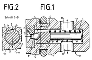
- FIG. 1 shows an embodiment of a valve acting as a pressure relief valve, in which a valve tappet 1, which is guided in a valve housing 10 and is decachable, is provided in the area of the tappet head 7 with guide surfaces asymmetrically pressurized on the circumference. These guide surfaces 5 are interrupted by flute-shaped grooves, so that when the flow cross section 3 is released, the fluid can flow into the adjacent pressure medium channels 11.
- the valve tappet 1 has a valve spring 12 on the shaft end facing away from the valve closing member 6, the pretensioning force of which is matched to the excess pressure to be controlled. When the specified control pressure is reached opens the valve closing member 6 designed as a ball seat valve, the flow cross section, so that pressure medium can be drained from the operating system.
- valve tappet 1 In contrast to the valve tappet 1 with a transverse displacement effect, the conventional valve tappet tends to radial vibrations during the valve opening phases, so that noises arise from the impulsive radial contacting of the guide surfaces on the valve housing wall, which are perceived as disturbing.
- FIG. 2 shows the cross-section BB of the tappet head 7 according to the invention, which has an asymmetrical distribution of the recesses 4 over the circumference instead of a symmetrical one. Consequently, after release of the flow cross-section 3 between the valve closing member 6 and the valve seat 2, the pressure medium can flow over the two recesses 4 shown in the illustration, as a result of the asymmetrical pressurization of the tappet head 7, resulting in a compressive force for res eccentric alignment of the tappet head 7 on the recesses 4 opposite guide surface 5 to the valve housing 10 provides.
- a solution to the noise problem has thus been found in a functionally appropriate manner, which excludes radial vibrations using simple means.
Landscapes
- Physics & Mathematics (AREA)
- Engineering & Computer Science (AREA)
- Electromagnetism (AREA)
- Fluid Mechanics (AREA)
- Transportation (AREA)
- Mechanical Engineering (AREA)
- Lift Valve (AREA)
- Magnetically Actuated Valves (AREA)
- Regulating Braking Force (AREA)
- Details Of Valves (AREA)
Applications Claiming Priority (3)
| Application Number | Priority Date | Filing Date | Title |
|---|---|---|---|
| DE3930757 | 1989-09-14 | ||
| DE3930757A DE3930757A1 (de) | 1989-09-14 | 1989-09-14 | Ventil, insbesondere fuer schlupfgeregelte hydraulische bremsanlagen |
| PCT/EP1990/001520 WO1991004181A1 (de) | 1989-09-14 | 1990-09-08 | Ventil, insbesondere für schlupfgeregelte hydraulische bremsanlagen |
Publications (2)
| Publication Number | Publication Date |
|---|---|
| EP0442993A1 EP0442993A1 (de) | 1991-08-28 |
| EP0442993B1 true EP0442993B1 (de) | 1994-08-17 |
Family
ID=6389453
Family Applications (1)
| Application Number | Title | Priority Date | Filing Date |
|---|---|---|---|
| EP90912812A Expired - Lifetime EP0442993B1 (de) | 1989-09-14 | 1990-09-08 | Ventil, insbesondere für schlupfgeregelte hydraulische bremsanlagen |
Country Status (5)
| Country | Link |
|---|---|
| US (1) | US5199769A (ja) |
| EP (1) | EP0442993B1 (ja) |
| JP (1) | JPH04501840A (ja) |
| DE (2) | DE3930757A1 (ja) |
| WO (1) | WO1991004181A1 (ja) |
Families Citing this family (22)
| Publication number | Priority date | Publication date | Assignee | Title |
|---|---|---|---|---|
| DE4028606A1 (de) * | 1990-09-08 | 1992-03-26 | Teves Gmbh Alfred | Druckregelventil, insbesondere zur druckmittelsteuerung in schlupfgeregelten, hydraulischen bremsanlagen |
| DE4135232C2 (de) * | 1991-10-25 | 2000-10-05 | Continental Teves Ag & Co Ohg | Elektromagnetventil, insbesondere für hydraulische Bremsanlagen mit Schlupfregelung |
| DE4137123A1 (de) * | 1991-11-12 | 1993-05-13 | Teves Gmbh Alfred | Drucksteuerventil |
| US5458406A (en) * | 1994-01-14 | 1995-10-17 | Itt Corporation | Electronic pressure relief system for traction control |
| DE4406777A1 (de) * | 1994-03-02 | 1995-09-07 | Teves Gmbh Alfred | Elektromagnetventil, insbesondere für schlupfgeregelte Kraftfahrzeugbremsanlagen |
| DE19509145B4 (de) * | 1995-03-14 | 2005-09-29 | Bosch Rexroth Ag | Wegesitzventil |
| DE19545333A1 (de) * | 1995-12-05 | 1997-06-12 | Bosch Gmbh Robert | Ventilschließkörper und Verfahren und Vorrichtung zur Herstellung von Dichtsitzen an Ventilschließkörpern |
| DE19604889C2 (de) * | 1996-02-10 | 2003-01-30 | Bosch Gmbh Robert | Druckbegrenzungsventil |
| SE9703810D0 (sv) * | 1997-10-20 | 1997-10-20 | Siemens Elema Ab | Ventil |
| DE19962960A1 (de) * | 1999-12-24 | 2001-06-28 | Bosch Gmbh Robert | Druckregelventil und Verfahren zum Herstellen eines Druckregelventils |
| DE10046416C2 (de) * | 2000-09-18 | 2002-11-07 | Orange Gmbh | Ventilausbildung für Steuerventile |
| JP4810647B2 (ja) * | 2006-06-16 | 2011-11-09 | 株式会社テージーケー | 差圧弁 |
| JP4613907B2 (ja) * | 2006-12-21 | 2011-01-19 | トヨタ自動車株式会社 | 電磁弁 |
| JP4734264B2 (ja) * | 2007-02-01 | 2011-07-27 | 日信工業株式会社 | 電磁弁 |
| DE102008043149A1 (de) | 2008-10-24 | 2010-04-29 | Robert Bosch Gmbh | Druckregelventil |
| JP5234101B2 (ja) * | 2010-12-21 | 2013-07-10 | トヨタ自動車株式会社 | 電磁弁 |
| US9545694B2 (en) | 2013-07-18 | 2017-01-17 | Valentin POSTEVKA | Cylindrical valve assembly |
| DE102013220331B4 (de) * | 2013-10-09 | 2025-08-21 | Robert Bosch Gmbh | Elektromagnetisch betätigbares Ventil |
| WO2017052568A1 (en) * | 2015-09-24 | 2017-03-30 | Postevka Valentin | Cylindrical valve assembly |
| DE102015218557A1 (de) * | 2015-09-28 | 2017-03-30 | Robert Bosch Gmbh | Ventileinrichtung, insbesondere zur Drosselung einer Druckmittelströmung in einem Druckmittel führenden Kanal sowie Dämpfungseinrichtung, insbesondere zur Dämpfung von Druckpulsationen in einem Bremskreis einer schlupfregelbaren Fahrzeugbremsanlage |
| JP6976583B2 (ja) * | 2019-04-03 | 2021-12-08 | 株式会社不二工機 | 弁装置 |
| CN113719656B (zh) * | 2021-08-30 | 2022-06-14 | 华中科技大学 | 一种随动式阀芯组件、直动式溢流阀和先导式溢流阀 |
Family Cites Families (14)
| Publication number | Priority date | Publication date | Assignee | Title |
|---|---|---|---|---|
| US2345379A (en) * | 1942-07-02 | 1944-03-28 | Westinghouse Air Brake Co | Drain valve mechanism |
| US3003423A (en) * | 1957-07-11 | 1961-10-10 | Thompson Ramo Wooldridge Inc | Pressure control valve |
| US3354898A (en) * | 1966-05-02 | 1967-11-28 | Standard Screw | Crankcase ventilating valve having rotatable metering plunger |
| US3465787A (en) * | 1967-04-12 | 1969-09-09 | Gen Electric | Spring-biased valve with anti-chattering feature |
| GB1221185A (en) * | 1967-12-19 | 1971-02-03 | Ass Elect Ind | Improvements in or relating to fluid control valves |
| GB1330011A (en) * | 1970-03-25 | 1973-09-12 | Girling Ltd | Valves for controlling the flow of hydraulic fluids |
| DE2052307A1 (de) * | 1970-10-24 | 1972-05-25 | Teves Gmbh Alfred | Elektromagnetisch betätigtes Sitzventil |
| US3782412A (en) * | 1972-05-11 | 1974-01-01 | Weatherland Co | Unbalanced poppet relief valve |
| CA1021225A (en) * | 1974-06-28 | 1977-11-22 | General Signal Corporation | Quick-acting valve assembly |
| DE2625961A1 (de) * | 1976-06-10 | 1977-12-22 | Knorr Bremse Gmbh | Membranventil |
| US4030520A (en) * | 1976-08-05 | 1977-06-21 | Sands Asa D | Ball-type safety valve |
| DE3040540A1 (de) * | 1980-10-28 | 1982-05-27 | Alfred Teves Gmbh, 6000 Frankfurt | Fremdenergiegespeiste bremsschlupfregelanlage eines hydraulischen fahrzeugbremssystems |
| WO1986004657A1 (en) * | 1985-02-08 | 1986-08-14 | Dibartolo Ernest A | Direct-acting, differential piston relief valve |
| DE3713661A1 (de) * | 1987-04-24 | 1988-11-17 | Teves Gmbh Alfred | Rueckschlagventil |
-
1989
- 1989-09-14 DE DE3930757A patent/DE3930757A1/de not_active Withdrawn
-
1990
- 1990-09-08 EP EP90912812A patent/EP0442993B1/de not_active Expired - Lifetime
- 1990-09-08 US US07/688,949 patent/US5199769A/en not_active Expired - Fee Related
- 1990-09-08 JP JP2512160A patent/JPH04501840A/ja active Pending
- 1990-09-08 WO PCT/EP1990/001520 patent/WO1991004181A1/de not_active Ceased
- 1990-09-08 DE DE59006839T patent/DE59006839D1/de not_active Expired - Fee Related
Also Published As
| Publication number | Publication date |
|---|---|
| WO1991004181A1 (de) | 1991-04-04 |
| DE59006839D1 (de) | 1994-09-22 |
| EP0442993A1 (de) | 1991-08-28 |
| JPH04501840A (ja) | 1992-04-02 |
| US5199769A (en) | 1993-04-06 |
| DE3930757A1 (de) | 1991-03-28 |
Similar Documents
| Publication | Publication Date | Title |
|---|---|---|
| EP0951412B1 (de) | Magnetventil | |
| EP0503013B1 (de) | Elektromagnetventil für hydraulische bremsanlagen mit schlupfregelung | |
| EP0842074B1 (de) | Elektromagnetventil, insbesondere für hydraulische kraftfahrzeugbremsanlagen mit radschlupfregelung | |
| DE3802648C2 (ja) | ||
| WO1991004181A1 (de) | Ventil, insbesondere für schlupfgeregelte hydraulische bremsanlagen | |
| EP0325958B1 (de) | Hydraulisch gesteuertes Ventil | |
| DE69715712T2 (de) | Hydraulisches Elektromagnetventil | |
| DE19531010B4 (de) | Magnetventil, insbesondere für eine schlupfgeregelte, hydraulische Bremsanlage für Kraftfahrzeuge | |
| DE4137123A1 (de) | Drucksteuerventil | |
| DE10321413B4 (de) | Elektromagnetisch betätigbares Ventil | |
| DE4344440A1 (de) | Elektromagnetventil, insbesondere für schlupfgeregelte Kraftfahrzeugbremsanlagen | |
| EP0607370B2 (de) | Kolben mit zentralventil für hydraulische bremsanlagen | |
| DE19536619B4 (de) | Ventil für eine hydraulische Bremsanlage für Kraftfahrzeuge | |
| DE19716856B4 (de) | Baueinheit für ein Hydraulikventil | |
| EP0752942B1 (de) | Elektromagnetisch betätigtes ventil, insbesondere für schlupfgeregelte hydraulische bremsanlagen in kraftfahrzeugen | |
| EP1427917A1 (de) | Hydraulisch gesteuerter aktuator zur betätigung eines ventils | |
| DE10311486A1 (de) | Elektromagnetventil | |
| DE3412351C2 (ja) | ||
| DE69926384T2 (de) | Elektromagnetisches steuerventil | |
| DE3023027C2 (de) | Nichtdruckausgeglichene hydraulische Ventilvorrichtung, insbesondere für Kraftfahrzeugbremsanlagen | |
| DE102016216293B4 (de) | Elektromagnetventil, insbesondere für schlupfgeregelte Kraftfahrzeugbremsanlagen | |
| DE102018220673A1 (de) | Elektromagnetventil, insbesondere für schlupfgeregelte Kraftfahrzeugbremsanlagen | |
| EP0966380B1 (de) | Druckregelventil | |
| DE4432046A1 (de) | Elektromagnetisch betätigtes Ventil, insbesondere für schlupfgeregelte hydraulische Bremsanlagen in Kraftfahrzeugen | |
| DE19703759A1 (de) | Mehrwege-Regelventil |
Legal Events
| Date | Code | Title | Description |
|---|---|---|---|
| PUAI | Public reference made under article 153(3) epc to a published international application that has entered the european phase |
Free format text: ORIGINAL CODE: 0009012 |
|
| 17P | Request for examination filed |
Effective date: 19910223 |
|
| AK | Designated contracting states |
Kind code of ref document: A1 Designated state(s): DE FR GB |
|
| 17Q | First examination report despatched |
Effective date: 19920616 |
|
| RAP1 | Party data changed (applicant data changed or rights of an application transferred) |
Owner name: ITT AUTOMOTIVE EUROPE GMBH |
|
| GRAA | (expected) grant |
Free format text: ORIGINAL CODE: 0009210 |
|
| AK | Designated contracting states |
Kind code of ref document: B1 Designated state(s): DE FR GB |
|
| REF | Corresponds to: |
Ref document number: 59006839 Country of ref document: DE Date of ref document: 19940922 |
|
| GBT | Gb: translation of ep patent filed (gb section 77(6)(a)/1977) |
Effective date: 19940831 |
|
| ET | Fr: translation filed | ||
| PLBE | No opposition filed within time limit |
Free format text: ORIGINAL CODE: 0009261 |
|
| STAA | Information on the status of an ep patent application or granted ep patent |
Free format text: STATUS: NO OPPOSITION FILED WITHIN TIME LIMIT |
|
| 26N | No opposition filed | ||
| PGFP | Annual fee paid to national office [announced via postgrant information from national office to epo] |
Ref country code: GB Payment date: 19950817 Year of fee payment: 6 |
|
| PGFP | Annual fee paid to national office [announced via postgrant information from national office to epo] |
Ref country code: FR Payment date: 19950904 Year of fee payment: 6 |
|
| PGFP | Annual fee paid to national office [announced via postgrant information from national office to epo] |
Ref country code: DE Payment date: 19951107 Year of fee payment: 6 |
|
| PG25 | Lapsed in a contracting state [announced via postgrant information from national office to epo] |
Ref country code: GB Effective date: 19960908 |
|
| PG25 | Lapsed in a contracting state [announced via postgrant information from national office to epo] |
Ref country code: FR Effective date: 19960930 |
|
| GBPC | Gb: european patent ceased through non-payment of renewal fee |
Effective date: 19960908 |
|
| PG25 | Lapsed in a contracting state [announced via postgrant information from national office to epo] |
Ref country code: DE Effective date: 19970603 |
|
| REG | Reference to a national code |
Ref country code: FR Ref legal event code: ST |
|
| REG | Reference to a national code |
Ref country code: FR Ref legal event code: ST |