EP0443099B1 - Système de réfrigération - Google Patents
Système de réfrigération Download PDFInfo
- Publication number
- EP0443099B1 EP0443099B1 EP90121437A EP90121437A EP0443099B1 EP 0443099 B1 EP0443099 B1 EP 0443099B1 EP 90121437 A EP90121437 A EP 90121437A EP 90121437 A EP90121437 A EP 90121437A EP 0443099 B1 EP0443099 B1 EP 0443099B1
- Authority
- EP
- European Patent Office
- Prior art keywords
- temperature
- evaporator
- compressor
- line
- expansion valve
- Prior art date
- Legal status (The legal status is an assumption and is not a legal conclusion. Google has not performed a legal analysis and makes no representation as to the accuracy of the status listed.)
- Expired - Lifetime
Links
Images


Classifications
-
- B—PERFORMING OPERATIONS; TRANSPORTING
- B60—VEHICLES IN GENERAL
- B60H—ARRANGEMENTS OF HEATING, COOLING, VENTILATING OR OTHER AIR-TREATING DEVICES SPECIALLY ADAPTED FOR PASSENGER OR GOODS SPACES OF VEHICLES
- B60H1/00—Heating, cooling or ventilating devices
- B60H1/32—Cooling devices
- B60H1/3204—Cooling devices using compression
- B60H1/3205—Control means therefor
- B60H1/321—Control means therefor for preventing the freezing of a heat exchanger
-
- B—PERFORMING OPERATIONS; TRANSPORTING
- B60—VEHICLES IN GENERAL
- B60H—ARRANGEMENTS OF HEATING, COOLING, VENTILATING OR OTHER AIR-TREATING DEVICES SPECIALLY ADAPTED FOR PASSENGER OR GOODS SPACES OF VEHICLES
- B60H1/00—Heating, cooling or ventilating devices
- B60H1/32—Cooling devices
- B60H1/3204—Cooling devices using compression
- B60H1/3205—Control means therefor
- B60H1/3211—Control means therefor for increasing the efficiency of a vehicle refrigeration cycle
-
- F—MECHANICAL ENGINEERING; LIGHTING; HEATING; WEAPONS; BLASTING
- F25—REFRIGERATION OR COOLING; COMBINED HEATING AND REFRIGERATION SYSTEMS; HEAT PUMP SYSTEMS; MANUFACTURE OR STORAGE OF ICE; LIQUEFACTION SOLIDIFICATION OF GASES
- F25B—REFRIGERATION MACHINES, PLANTS OR SYSTEMS; COMBINED HEATING AND REFRIGERATION SYSTEMS; HEAT PUMP SYSTEMS
- F25B41/00—Fluid-circulation arrangements
- F25B41/30—Expansion means; Dispositions thereof
- F25B41/31—Expansion valves
- F25B41/33—Expansion valves with the valve member being actuated by the fluid pressure, e.g. by the pressure of the refrigerant
- F25B41/335—Expansion valves with the valve member being actuated by the fluid pressure, e.g. by the pressure of the refrigerant via diaphragms
-
- F—MECHANICAL ENGINEERING; LIGHTING; HEATING; WEAPONS; BLASTING
- F25—REFRIGERATION OR COOLING; COMBINED HEATING AND REFRIGERATION SYSTEMS; HEAT PUMP SYSTEMS; MANUFACTURE OR STORAGE OF ICE; LIQUEFACTION SOLIDIFICATION OF GASES
- F25B—REFRIGERATION MACHINES, PLANTS OR SYSTEMS; COMBINED HEATING AND REFRIGERATION SYSTEMS; HEAT PUMP SYSTEMS
- F25B41/00—Fluid-circulation arrangements
- F25B41/30—Expansion means; Dispositions thereof
- F25B41/31—Expansion valves
- F25B41/34—Expansion valves with the valve member being actuated by electric means, e.g. by piezoelectric actuators
- F25B41/355—Expansion valves with the valve member being actuated by electric means, e.g. by piezoelectric actuators by electric heating of bimetal elements, shape memory elements or heat expanding elements
-
- F—MECHANICAL ENGINEERING; LIGHTING; HEATING; WEAPONS; BLASTING
- F25—REFRIGERATION OR COOLING; COMBINED HEATING AND REFRIGERATION SYSTEMS; HEAT PUMP SYSTEMS; MANUFACTURE OR STORAGE OF ICE; LIQUEFACTION SOLIDIFICATION OF GASES
- F25B—REFRIGERATION MACHINES, PLANTS OR SYSTEMS; COMBINED HEATING AND REFRIGERATION SYSTEMS; HEAT PUMP SYSTEMS
- F25B47/00—Arrangements for preventing or removing deposits or corrosion, not provided for in another subclass
- F25B47/006—Arrangements for preventing or removing deposits or corrosion, not provided for in another subclass for preventing frost
-
- B—PERFORMING OPERATIONS; TRANSPORTING
- B60—VEHICLES IN GENERAL
- B60H—ARRANGEMENTS OF HEATING, COOLING, VENTILATING OR OTHER AIR-TREATING DEVICES SPECIALLY ADAPTED FOR PASSENGER OR GOODS SPACES OF VEHICLES
- B60H1/00—Heating, cooling or ventilating devices
- B60H1/32—Cooling devices
- B60H2001/3236—Cooling devices information from a variable is obtained
- B60H2001/3248—Cooling devices information from a variable is obtained related to pressure
- B60H2001/3252—Cooling devices information from a variable is obtained related to pressure of the refrigerant at an evaporating unit
-
- B—PERFORMING OPERATIONS; TRANSPORTING
- B60—VEHICLES IN GENERAL
- B60H—ARRANGEMENTS OF HEATING, COOLING, VENTILATING OR OTHER AIR-TREATING DEVICES SPECIALLY ADAPTED FOR PASSENGER OR GOODS SPACES OF VEHICLES
- B60H1/00—Heating, cooling or ventilating devices
- B60H1/32—Cooling devices
- B60H2001/3236—Cooling devices information from a variable is obtained
- B60H2001/3255—Cooling devices information from a variable is obtained related to temperature
- B60H2001/3258—Cooling devices information from a variable is obtained related to temperature of the air at a condensing unit
-
- B—PERFORMING OPERATIONS; TRANSPORTING
- B60—VEHICLES IN GENERAL
- B60H—ARRANGEMENTS OF HEATING, COOLING, VENTILATING OR OTHER AIR-TREATING DEVICES SPECIALLY ADAPTED FOR PASSENGER OR GOODS SPACES OF VEHICLES
- B60H1/00—Heating, cooling or ventilating devices
- B60H1/32—Cooling devices
- B60H2001/3236—Cooling devices information from a variable is obtained
- B60H2001/3255—Cooling devices information from a variable is obtained related to temperature
- B60H2001/3263—Cooling devices information from a variable is obtained related to temperature of the refrigerant at an evaporating unit
-
- B—PERFORMING OPERATIONS; TRANSPORTING
- B60—VEHICLES IN GENERAL
- B60H—ARRANGEMENTS OF HEATING, COOLING, VENTILATING OR OTHER AIR-TREATING DEVICES SPECIALLY ADAPTED FOR PASSENGER OR GOODS SPACES OF VEHICLES
- B60H1/00—Heating, cooling or ventilating devices
- B60H1/32—Cooling devices
- B60H2001/3269—Cooling devices output of a control signal
- B60H2001/3285—Cooling devices output of a control signal related to an expansion unit
-
- F—MECHANICAL ENGINEERING; LIGHTING; HEATING; WEAPONS; BLASTING
- F25—REFRIGERATION OR COOLING; COMBINED HEATING AND REFRIGERATION SYSTEMS; HEAT PUMP SYSTEMS; MANUFACTURE OR STORAGE OF ICE; LIQUEFACTION SOLIDIFICATION OF GASES
- F25B—REFRIGERATION MACHINES, PLANTS OR SYSTEMS; COMBINED HEATING AND REFRIGERATION SYSTEMS; HEAT PUMP SYSTEMS
- F25B2341/00—Details of ejectors not being used as compression device; Details of flow restrictors or expansion valves
- F25B2341/06—Details of flow restrictors or expansion valves
- F25B2341/068—Expansion valves combined with a sensor
- F25B2341/0683—Expansion valves combined with a sensor the sensor is disposed in the suction line and influenced by the temperature or the pressure of the suction gas
-
- Y—GENERAL TAGGING OF NEW TECHNOLOGICAL DEVELOPMENTS; GENERAL TAGGING OF CROSS-SECTIONAL TECHNOLOGIES SPANNING OVER SEVERAL SECTIONS OF THE IPC; TECHNICAL SUBJECTS COVERED BY FORMER USPC CROSS-REFERENCE ART COLLECTIONS [XRACs] AND DIGESTS
- Y02—TECHNOLOGIES OR APPLICATIONS FOR MITIGATION OR ADAPTATION AGAINST CLIMATE CHANGE
- Y02B—CLIMATE CHANGE MITIGATION TECHNOLOGIES RELATED TO BUILDINGS, e.g. HOUSING, HOUSE APPLIANCES OR RELATED END-USER APPLICATIONS
- Y02B30/00—Energy efficient heating, ventilation or air conditioning [HVAC]
- Y02B30/70—Efficient control or regulation technologies, e.g. for control of refrigerant flow, motor or heating
Definitions
- the invention relates to a refrigeration system to be operated on board a motor vehicle with a compressor, a condenser and an evaporator and an electrically controllable thermostatic expansion valve between the condenser and the evaporator, the latter having an electrically controllable actuating element which regulates the superheating of the refrigerant vapor can be controlled by a signal which is derived from the temperature in the line between the compressor and the condenser and from the temperature in the line behind the evaporator, the temperature being detectable by means of a sensor.
- Such a refrigeration system is known from US-A-4,878,355.
- the delivery capacity of the compressor is subject to constant changes in the refrigeration systems of a motor vehicle because it is driven by the motor of the motor vehicle and its speed is constantly changing.
- These constantly changing operating conditions of the refrigeration system make optimal operation difficult.
- a particularly critical operating state arises when the vehicle is at a standstill, in which the compressor runs from that running at idling speed Vehicle engine is driven.
- the ventilation of the condenser is very unfavorable in this operating state, which can lead to particularly high bridges and hot gas temperatures. High driving speeds in low gear are also critical.
- the high compressor speeds that occur lead to critical hot gas temperatures.
- the characteristic of the expansion valve between the condenser and the evaporator is decisive for reaching or at least getting close to the desired maximum temperature behind the compressor. It is important to record various parameters of the refrigerant circuit and to use them to control the expansion valve.
- the temperature t 1 in the line between the compressor and the condenser and also the temperature t 2 in the line behind the evaporator is detected and used for control purposes of the expansion valve. This leads to usable, but not optimal results of a refrigeration system operated in a motor vehicle.
- the signal derived from the temperature t1 controls the actuator of the expansion valve such that the superheating ⁇ t Ü of the refrigerant vapor in the line behind the evaporator is regulated when the temperature t1 in the line behind the compressor is one exceeds certain value t 1max and that additionally the pressure p2 in the line behind the evaporator is used to regulate the superheat ⁇ t Ü of the refrigerant vapor.
- refrigerant vapor (suction gas) is drawn in by a compressor 1 at low pressure and low temperature and brought to a higher pressure.
- the refrigerant is heated.
- the condenser 2 the liquefaction takes place at high pressure with heat being given off to the environment.
- the liquefied refrigerant then reaches an expansion valve 4, in which it passes through a throttle point 3 (see FIG. 2).
- the throttling leads to a decrease in pressure and temperature with partial evaporation of the liquid refrigerant.
- the refrigerant then reaches the evaporator 5. There, the refrigerant is removed from the environment to be cooled, e.g. the interior of a motor vehicle, heat is supplied.
- the refrigerant vapor (suction gas) reaches the suction gas chamber 6 of the expansion valve 4 and from there to the heat exchanger 5 ', which e.g. is a fuel cooler of a motor vehicle. From the heat exchanger 5 ', the refrigerant vapor reaches the compressor 1; the cycle begins there again.
- FIG. 2 shows, as a possible implementation, an electronically controllable thermostatic expansion valve, as already described in German patent application P 38 29 101.0, which was filed on August 27, 1988, there as an exemplary embodiment according to FIG. 8.
- the suction gas chamber 6 acts on one side of the membrane 8 in the control head 7.
- the closed space on the other side the membrane 8 is filled with a control medium 9.
- a certain position of the membrane 8 is established, which determines the flow cross-section of the throttle point 3 via the transmission rod 10, at the lower end of which the throttle body 11 is provided.
- a spring 12 acts on the throttle body 11 from below, the compression of which can be adjusted by a spindle 13.
- the expansion valve 4 according to FIG. 2 also has a PTC heating plate 90 (positive temperature coefficient), which can be electrically heated via a connecting line 91, so that in addition to the control described, a further external control is possible. If, for example, an electrical signal is applied to the heating plate 90, this leads to an expansion of the control medium 9 and thus to a further opening of the throttle point 3.
- the entire control head 7 is enclosed by an insulating cap 92.
- the PTC heating element has the property of increasing the heating power by increasing the resistance above a certain temperature limit, which protects the entire valve head from excessive temperatures.
- the driving signal arrives at the heating plate 90 from a control device 100.
- the "overheating" of the refrigerant vapor behind the evaporator 5 influences the part of the liquid refrigerant which remains dissolved in the oil added to the compressor for lubrication and thus does not contribute to cooling.
- this proportion of refrigerant dissolved in the oil decreases with increasing overheating.
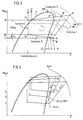
- Overheating is the temperature difference between the gaseous refrigerant t2 at the end of the evaporator and the saturation temperature as a wet steam / oil mixture at the same pressure p2.
- This pressure is formally related to the so-called saturation temperature t p2 at the saturation line between wet steam and steam.
- curve S 'de denotes the saturation line between liquid and wet steam or curve S''denotes the saturation line between wet steam and refrigerant vapor.
- the liquid turns directly into vapor.
- the temperature values are entered for clarification.
- the superheat ⁇ t ü behind the evaporator 5 is, for example, 5 K. Under the assumed operating conditions, this leads to the refrigerant vapor behind the compressor 1 having the maximum permissible temperature t max ( ⁇ t 1max ) of e.g. 150 ° C reached.
- the superheat ⁇ t ü after the evaporator 5 is, for example, 3 K with the result that behind the compressor 1 only a temperature of the refrigerant vapor of approximately 130 ° C. is reached becomes.
- Figure 3 is also the completion of the passage through the Expansion valve 4 occurring pressure loss ⁇ p EX and the pressure loss ⁇ p V occurring in the evaporator 5 are entered.
- the ventilation of the condenser is the most unfavorable in this case, so that particularly high pressures and hot gas temperatures can occur.
- the driving state 32/2 is relatively unproblematic;
- the driving condition 64/2 is more problematic, as critical hot gas temperatures occur due to high compressor speeds.
- the overheating should be, for example, 8K, depending on the refrigerant used, the type and amount of the cooling oil.
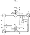
- FIG. 1 is used in the refrigerant circuit according to Figure 1, an electronically controllable thermostatic expansion valve 4 and controls it in the manner shown on the basis of a signal that from the temperature t 1 in the line 102 with a sensor 101 behind the compressor 1 and before is derived from the capacitor 2, the desired characteristic can be obtained with a control device 100 Realize in which the maximum temperature t max to be maintained there is used as a control variable for controlling the throttle point 3 in the expansion valve 4 (cf. FIG. 2).
- 1 contains a simplified and systematic clarification of FIG. 5. It differs from FIG.
- the action of the temperature t 2 or the pressure p 2 takes place on the control head 107 of the expansion valve 104.
- the action of the control signal derived in the control device 100 for the expansion valve 104 takes place via an actuating member (actuator) 190. In FIG. 2, this actuator is activated by the heating plate 91 educated.
- control device 100 leads a further line to a clutch 108.
- a further sensor 110 which determines the rotational speed (s) of the drive shaft, is provided on the drive shaft 109 'of the compressor 1 and is likewise supplied as an input variable to the control device 100 and can also be taken into account there to improve the control loop timing behavior.
- a third sensor t3 measures the temperature of the air-side evaporator surface or the air temperature after evaporation to detect any ice formation on the air-side evaporator surface. If the temperature falls below a minimum t 3min , the control unit 100 can also influence the actuating element 190.
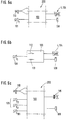
- FIG. 6 (a) shows a generalization in which the control device 100 is part of a more extensive control device 200, for example a microprocessor, which also performs other tasks (compressor control, fan control).
- the control device 100 is used to control overheating, ie to control the overheating ⁇ t ü behind the evaporator 5 in such a way that the maximum permissible temperature t 1 behind the compressor 1 does not exceed its permissible maximum value t 1 max .
- the output of the control device 100 goes to the expansion valve 4 or 104, as well as the clutch 108.
- the control unit 100 is also fed the speed from the sensor 110, which, however, can also control further units of the control device 200 with this information.
- FIG. 6 (b) schematically shows a simple form of implementation, as a low-cost solution, in which the control device 100 is implemented only by a double T switch, one of which is a contact pair in the event of a change in the setting of the setpoint on the expansion valve 4 or 104 is closed, otherwise open, and the other pair of contacts 113 is to be opened if the compressor coupling 108 has to be released.
- Figure 6 (c) shows a generalization of the concept of Figure 6 (a), which assumes that p2 and t2 do not act directly on the expansion valve 4 or 104 in the sense of a thermostatic control as shown in FIG. 2, but via external Sensors reach the control device 100 and are evaluated there, and that the control device 100 then controls a simple injection valve 115 that can be actuated by an electric motor.
- FIG. 7 shows the control loop including the measuring points in front of and behind the evaporator 5 and the compressor 1 in order to deepen the understanding of the invention
- Evaporator 5 the expansion valve (or injection valve) 4, 104 is arranged, the throttle point (corresponding to throttle point 3 in Figure 2) is adjusted by an actuator 120 (corresponding to the transmission rod 10 in Figure 2).
- This actuating member 120 is activated in its setting movement by the valve control system 130 (corresponding to the control media 9 in FIG. 2 in the components 8-13).
- the graphic design of the logic circuit 133 with the information "+" and "-" takes into account the fact that an increased pressure p2 to reduce the flow cross section of the throttle point (eg throttle point 3 in Fig. 2), but an increased temperature t2 - in Consequence of the regulation of the overheating - should lead to an increase in the flow cross section of the expansion valve 104. So you can, after appropriate conversion of the signals for t2 and p2 in converters 134 and 135, form the logic circuit 133 as a subtractor.
- a manipulated variable arrives at the second input 132 of the valve control system 130 and is derived from the two variables in the link 136 - again in the form of a subtractor, for example.
- One size corresponds to a fixed, albeit adjustable, default setting for one Setpoint of overheating ⁇ t ü .
- the presetting is carried out by the position of the spindle 13 and thus the bias of the spring 12.
- the second variable w2 which arrives at the logic circuit 136 and which is controlled by a further actuator 140, the 2 corresponds to the heating plate 90, goes out.
- the actuator 140 in turn receives its control from the control circuit 100. It is supplied with the quantity w 3, which is derived from the sensor 101 in the line 102 to the compressor 1 and corresponds to the prevailing temperature t 1 there, which corresponds to a specific maximum temperature t max , as discussed above, must not exceed.
- further control variables can be given to the control device 100, for example w z , for example as protection against icing, or z z ; the latter can be used to find further disturbance variables and / or parameters, such as compressor speed, driving speed, ambient temperature, outside temperature, etc., in the control circuit as parameters.
- Figures 8 (a), (b), (c) show the characteristics as they are have resulted in a practical implementation of the invention.
- Figure 8 (a) shows the heating power (N, measured in watts) of a heating plate 90 (according to Figure 2), which was used in a circuit according to Figure 1, Figure 5 or Figure 7.
- Figure 8 (b) shows the hot gas temperature behind the compressor 1 and Figure 8 (c) the temperature of the refrigerant vapor after the evaporator 5.
- the superheat ⁇ t ü in K is plotted on the abscissa.
- the overheating ⁇ t ü increases .
- the temperature r increases behind the compressor.
- the temperature after the evaporator drops. So there must always be a control or regulation such that, on the one hand, t 1 does not exceed its maximum value, but on the other hand, while maintaining this maximum value, maximum cooling, ie the lowest possible temperature t 2, is obtained.
- the curves according to FIG. 9a in particular the middle one, show that at an overheating temperature of ⁇ t ü about 8K there is a maximum of the evaporator power Q V.
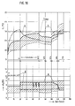
- Figure 10 now shows the behavior of an air conditioning system according to Figure 1, 5 or 7 in the vehicle under different operating conditions, wherein in the upper part of Figure 10 t1 in ° C, ie the temperature behind the compressor, and in the lower range ⁇ t ü in ° K, overheating is applied.
- the diagrams show a typical behavior of a vehicle air conditioning system at an ambient temperature of 40 ° C, at 40% relative humidity and a solar load on the vehicle of 1000 W / m2.
- the indication "speed step” means the shift position of the automatic transmission.
- the dash-dotted curve A represents the course of the temperature t 1 behind the compressor when using a conventional thermostatic expansion valve without control depending on the overheating. It shows that both relatively quickly in idle, after about 15 minutes and then again towards the end of the test sequence, in 2nd gear at 64 km / h, ie relatively high speed of the engine, the temperature t 1 of the hot gas after the compressor becomes impermissibly high.
- Curve B drawn in a thick line, shows the course with control according to the invention. It can be seen that the temperature t 1 remains below the maximum permissible value t max as a result of the regulation of the overheating. One can assume a higher ⁇ t ü as the setpoint, since one can regulate if it gets too high.
- the hatched area is the area in which regulation or control can take place when a controllable thermostatic expansion valve is used. The overheating is entered in the lower area of FIG.
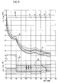
- FIG. 11 shows the course of the temperature t Lik in the vehicle in the headspace under the same operating conditions.
- the dash-dotted line drawn in strong lines indicates the course of the curve in a conventional thermostatic expansion valve which cannot be controlled; curve B, which is drawn in a strong line, indicates the course of the headspace temperature t Lik when the thermostatic expansion valve is activated as a function of the overheating.
- curve B the lowering of the temperature in the invention takes place more strongly than in the prior art, but that at low temperatures, which would result in an excessively high temperature downstream of the compressor, as a result of the curtailment of the Overheating, there is no further reduction in the headspace temperature, but a stabilization with a slight increase occurs, which, however, is still in the range that is acceptable at all times, especially since this does not only result in excessive stress on the air conditioning system, but also a possibly too uncomfortable cooling can be avoided.
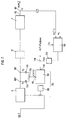
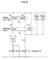
- FIG. 12 shows a simple circuit in a low-cost version in the manner as indicated in FIG. 6 a or b, somewhat more in detail.
- the first safety chain consists of switching elements according to the state of the art.
- the normally closed contact b11 opens when the hot gas temperature is too high, for example at t1> 150 ° C.
- the normally closed contact b21 opens when the evaporator ices up (icing protection), for example at t3 ⁇ 0 ° C.
- the switch B z with the further normally closed contact b z can take over further safety functions.
- M1 denotes the coupling of the compressor to its drive.
- the coil K1 receives a relay current and thus closes the contact K1 in a second chain, which is used to regulate the overheating by the expansion valve.
- the contacts b12 and b22 of the duo switches B1 and B2 and the switches B3 and Bx are open during normal operation of the refrigeration system, as a result of which the PTC heating plate 90 of the thermostatic expansion valve 4 or 104 according to FIG. 2 is not energized. In this case, the valve works with a high, optimal performance overheating.
- the switches B3 and BX can be used to pick up additional influencing variables. At the same time, additional switches can be provided.
- the circuit according to FIG. 12 can be expanded as desired, as indicated by the arrow at the top right in FIG. 12.
Landscapes
- Engineering & Computer Science (AREA)
- Physics & Mathematics (AREA)
- Thermal Sciences (AREA)
- Mechanical Engineering (AREA)
- General Engineering & Computer Science (AREA)
- Fluid Mechanics (AREA)
- Air-Conditioning For Vehicles (AREA)
- Control Of Positive-Displacement Pumps (AREA)
- Devices That Are Associated With Refrigeration Equipment (AREA)
Claims (10)
- Système de réfrigération destiné à être mis en service à bord d'un véhicule automobile et comprenant un compresseur (1), un condenseur (2) et un évaporateur (5) ainsi qu'une soupape thermostatique de détente (4, 104) commandée électriquement et montée entre le condenseur (2) et l'évaporateur (5), ce dernier comprenant un organe d'actionnement (90, 120, 190) commandé électriquement et qui peut être commandé pour le réglage de la surchauffe (Δtü) de la vapeur de l'agent réfrigérant par un signal qui est déduit de la température (t₁) régnant dans le conduit (102) situé entre le compresseur (1) et le condenseur (2) ainsi que de la température (t₂) régnant dans le conduit (103) situé derrière l'évaporateur (5), la température (t₁) étant détectable au moyen d'un capteur (101), caractérisé en ce que signal déduit de la température (t₁) attaque l'organe d'actionnement (90, 120, 190) de la soupape de détente (4, 104) de manière qu'aie lieu un réglage de la surchauffe (Δtü) de la vapeur de l'agent réfrigérant dans le conduit (103) lorsque la température (t₁) régnant dans le conduit (102) dépasse une valeur déterminée (tmax) et en ce qu'en plus la pression (P₂) régnant dans le conduit (103) situé derrière l'évaporateur (5) est utilisée pour le réglage de la surchauffe (Δtü) de la vapeur d'agent réfrigérant.
- Système de réfrigération selon la revendication 1, caractérisé en ce que, pour la protection contre le givrage de l'évaporateur, le signal déduit de la température (t₃) de la surface de l'évaporateur ou de l'air en aval de l'évaporateur (5), attaque l'organe d'actionnement (90, 120, 190) de la soupape de détente (4, 104) de manière qu'un réglage de la surchauffe (Δtü) de la vapeur d'agent réfrigérant ait lieu dans le conduit (130) situé derrière l'évaporateur (5) lorsque la température (t₃) de la surface de l'évaporateur ou de l'air se trouvant en aval de l'évaporateur (5) descend au-dessous d'une valeur déterminée.
- Système de réfrigération selon la revendication 1 ou 2, caractérisé en ce que le signal déduit du capteur (101) est converti dans un dispositif de commande (100) en un signal actionnant l'organe d'actionnement (90, 120, 120) de la soupape de détente (4, 104) et qui modifie la section de passage (3) de la soupape de détente (4, 104) dans le sens d'un agrandissement de la section de passage lorsque la température (t₁) régnant dans le conduit (102) situé entre le compresseur (1) et le condenseur (2) dépasse une valeur maximale déterminée admissible (tmax).
- Système de réfrigération selon au moins l'une des revendications précédentes, caractérisé en ce qu'un capteur (101) est prévu dans le conduit (102) situé entre le compresseur (1) et le condenseur (2) pour la détection de la température (t₁) et en ce que le signal qu'il en déduit est converti dans un dispositif de commande (5) en un signal actionnant l'organe d'actionnement (90, 120, 120) de la soupape de détente (4, 104) et qui modifie la section de passage (3) de la soupape de détente (4, 104) dans le sens d'une réduction de la section de passage lorsque la température (t₁) régnant dans le conduit (102) situé entre le compresseur (1) et le condenseur (2) descend au-dessous d'une valeur déterminée.
- Système de réfrigération selon au moins l'une des revendications précédentes, caractérisé en ce que l'effet de la pression (p₂) et de la température (t₂) de la vapeur de l'agent réfrigérant derrière (6) l'évaporateur (5) sur le système de réglage de soupape (8, 9, 10) de la soupape de détente (4, 104) est déterminé de manière que, lorsque la température (t₁) régnant dans le conduit (102) situé derrière le compresseur (1) n'atteint pas la valeur maximale admissible (tmax), il se produit dans le conduit (103) situé derrière l'évaporateur (5) une surchauffe (Δtü) à laquelle la capacité (Qv) de l'évaporateur (5) est un maximum.
- Système de réfrigération selon au moins l'une des revendications précédentes, caractérisé en ce que la surchauffe (Δtü) est réglée à environ 8K.
- Système de réfrigération selon la revendication 3 ou 4, caractérisé en ce que le dispositif de commande (100) comprend des contacts (112, 113 ; b₁₂) qui déclenchent ou enclenchent la commande de la soupape de détente (4, 104) en cas de dépassement vers le bas ou vers le haut d'une température déterminée dans le conduit (102) situé entre le compresseur (1) et le condenseur (2).
- Système de réfrigération selon au moins l'une des revendications précédentes, caractérisé en ce que le dispositif de commande (100) comprend d'autres dispositifs pour provoquer une modification de la surchauffe (Δtü) en fonction d'autres paramètres (wz, Zz).
- Système de réfrigération selon au moins l'une des revendications précédentes, caractérisé en ce qu'en cas de dépassement de la température maximale admissible (t₁) dans le conduit (102) situé en aval du compresseur (1), il se produit une coupure entre le moteur (109) d'entraînement du compresseur (1) et ce dernier.
- Système de réfrigération selon au moins l'une des revendications précédentes, caractérisé en ce que le dispositif de commande (100) traite également la vitesse de rotation du compresseur ou du moteur, qui représente une grandeur perturbatrice principale, pour l'amélioration de la fonction de transfert du circuit de réglage.
Applications Claiming Priority (2)
| Application Number | Priority Date | Filing Date | Title |
|---|---|---|---|
| DE4005728 | 1990-02-23 | ||
| DE4005728A DE4005728A1 (de) | 1990-02-23 | 1990-02-23 | Kaelteanlage |
Publications (3)
| Publication Number | Publication Date |
|---|---|
| EP0443099A2 EP0443099A2 (fr) | 1991-08-28 |
| EP0443099A3 EP0443099A3 (en) | 1993-02-03 |
| EP0443099B1 true EP0443099B1 (fr) | 1995-10-11 |
Family
ID=6400812
Family Applications (1)
| Application Number | Title | Priority Date | Filing Date |
|---|---|---|---|
| EP90121437A Expired - Lifetime EP0443099B1 (fr) | 1990-02-23 | 1990-11-09 | Système de réfrigération |
Country Status (3)
| Country | Link |
|---|---|
| EP (1) | EP0443099B1 (fr) |
| DE (2) | DE4005728A1 (fr) |
| ES (1) | ES2079418T3 (fr) |
Families Citing this family (14)
| Publication number | Priority date | Publication date | Assignee | Title |
|---|---|---|---|---|
| WO1994017346A1 (fr) * | 1993-01-19 | 1994-08-04 | Parker-Hannifin Corporation | Systeme de regulation de debit pour fluides de travail |
| JPH0849943A (ja) * | 1994-08-08 | 1996-02-20 | Yamaha Motor Co Ltd | エンジン駆動式熱ポンプ装置 |
| FR2725778B1 (fr) * | 1994-10-14 | 1996-12-13 | Soprano | Climatiseur pilote par un dispositif fournissant une mesure relative au fluide frigorigene utilise |
| DE4438683A1 (de) * | 1994-10-29 | 1996-05-02 | Man Nutzfahrzeuge Ag | Klimaanlage für Fahrzeuge |
| EP0837291B1 (fr) * | 1996-08-22 | 2005-01-12 | Denso Corporation | Système frigorifique du type à compression de vapeur |
| DE19647718C2 (de) | 1996-11-19 | 1998-09-24 | Danfoss As | Verfahren zur Regelung einer Kälteanlage sowie Kälteanlage und Expansionsventil |
| DE19706663B4 (de) * | 1997-02-20 | 2007-01-11 | Behr Gmbh & Co. Kg | Verfahren zur Regelung einer Klimaanlage in einem Kraftfahrzeug |
| DE19743629C2 (de) * | 1997-10-02 | 2000-05-11 | Behr Gmbh & Co | Klimaanlage für ein Kraftfahrzeug |
| US6050098A (en) * | 1998-04-29 | 2000-04-18 | American Standard Inc. | Use of electronic expansion valve to maintain minimum oil flow |
| DE19906497C2 (de) * | 1999-02-17 | 2002-12-05 | Behr Gmbh & Co | Verfahren und Einrichtung zur Regelung einer einen Kältespeicher umfassenden Klimaanlage |
| EP1148307B1 (fr) * | 2000-04-19 | 2004-03-17 | Denso Corporation | Chauffe-eau avec pompe à chaleur |
| US6460354B2 (en) | 2000-11-30 | 2002-10-08 | Parker-Hannifin Corporation | Method and apparatus for detecting low refrigerant charge |
| DE10220416A1 (de) * | 2002-05-08 | 2003-11-20 | Behr Gmbh & Co | Thermostatisches Expansionsventil |
| DE102004042887B3 (de) * | 2004-09-04 | 2006-01-19 | Audi Ag | Klimaanlage für ein Fahrzeug, insbesondere für ein Kraftfahrzeug |
Family Cites Families (13)
| Publication number | Priority date | Publication date | Assignee | Title |
|---|---|---|---|---|
| DE2749252C3 (de) * | 1977-11-03 | 1980-09-11 | Danfoss A/S, Nordborg (Daenemark) | Betätigungsvorrichtung für die Verstellung des Verschlußstücks eines Ventils |
| DE3212979A1 (de) * | 1982-04-07 | 1983-10-13 | Brown, Boveri & Cie Ag, 6800 Mannheim | Klimaanlage |
| FR2538518B1 (fr) * | 1982-12-22 | 1986-04-04 | Elf Aquitaine | Procede et dispositif de surveillance et de commande d'un evaporateur |
| US4542852A (en) * | 1984-03-05 | 1985-09-24 | The Singer Company | Vibration damping device for thermostatic expansion valves |
| JPS61197967A (ja) * | 1985-02-26 | 1986-09-02 | 株式会社ボッシュオートモーティブ システム | 冷房サイクル |
| DE3706152A1 (de) * | 1987-02-26 | 1988-09-08 | Sueddeutsche Kuehler Behr | Verfahren zur steuerung einer kraftfahrzeugklimaanlage und kraftfahrzeugklimaanlage zur durchfuehrung des verfahrens |
| DE3714120C1 (de) * | 1987-04-28 | 1988-04-21 | Emerson Electric Gmbh | Steueranordnung fuer ein Expansionsventil einer Kaelteanlage |
| JP2516986B2 (ja) * | 1987-07-06 | 1996-07-24 | 株式会社豊田自動織機製作所 | 車両空調用冷凍回路 |
| DE3815619A1 (de) * | 1988-05-07 | 1989-11-16 | Sueddeutsche Kuehler Behr | Einrichtung zur kuehlung elektrischer schaltschraenke |
| JP2834139B2 (ja) * | 1988-05-11 | 1998-12-09 | 株式会社日立製作所 | 冷凍装置 |
| DE3818584A1 (de) * | 1988-06-01 | 1989-12-14 | Hermle Kg Berthold | Kuehlvorrichtung fuer eine zentrifuge |
| DE3829101A1 (de) * | 1988-08-27 | 1990-03-01 | Sueddeutsche Kuehler Behr | Thermostatisches expansionsventil |
| US4878355A (en) * | 1989-02-27 | 1989-11-07 | Honeywell Inc. | Method and apparatus for improving cooling of a compressor element in an air conditioning system |
-
1990
- 1990-02-23 DE DE4005728A patent/DE4005728A1/de not_active Withdrawn
- 1990-11-09 EP EP90121437A patent/EP0443099B1/fr not_active Expired - Lifetime
- 1990-11-09 ES ES90121437T patent/ES2079418T3/es not_active Expired - Lifetime
- 1990-11-09 DE DE59009769T patent/DE59009769D1/de not_active Expired - Fee Related
Also Published As
| Publication number | Publication date |
|---|---|
| EP0443099A2 (fr) | 1991-08-28 |
| ES2079418T3 (es) | 1996-01-16 |
| EP0443099A3 (en) | 1993-02-03 |
| DE59009769D1 (de) | 1995-11-16 |
| DE4005728A1 (de) | 1991-08-29 |
Similar Documents
| Publication | Publication Date | Title |
|---|---|---|
| EP0443099B1 (fr) | Système de réfrigération | |
| DE3713869C2 (fr) | ||
| EP0640753B1 (fr) | Système de refroidissement pour un moteur à combustion interne | |
| DE2757832C2 (de) | Kühlanlage mit geschlossenem Kältemittelkreis | |
| DE3832226C2 (fr) | ||
| DE3706152A1 (de) | Verfahren zur steuerung einer kraftfahrzeugklimaanlage und kraftfahrzeugklimaanlage zur durchfuehrung des verfahrens | |
| EP0356642B1 (fr) | Soupape thermostatique de détente | |
| EP2828589A1 (fr) | Installation frigorifique | |
| DE102007010645A1 (de) | Verfahren zum Steuern einer Kompressionskälteanlage und eine Kompressionskälteanlage | |
| DE10053426C2 (de) | Klimaanlage für Fahrzeuge | |
| EP1355207A1 (fr) | Procédé de fonctionnement pour un système frigorifique à compression et système frigorifique à compression | |
| EP1350068B1 (fr) | Procede pour reguler un appareil de refroidissement | |
| DE4132719C2 (de) | Mehrtemperaturen-Kühlschrank | |
| DE102019109379A1 (de) | Verfahren zum Klimatisieren eines Fahrzeuginnenraums mit großem Volumen und hierfür eingerichtete Klimaanlage | |
| DE102012208819A1 (de) | Verfahren für die steuerung und regelung von kälteanlagen und wärmepumpen mit luftbeaufschlagtem verdampfer | |
| EP3922932A1 (fr) | Procédé de fonctionnement d'une installation de réfrigération à compression et installation de réfrigération à compression | |
| EP3548812A1 (fr) | Procédé pour faire fonctionner un compresseur frigorifique à vitesse variable | |
| DE3329661A1 (de) | Regelung von temperaturen, temperaturdifferenzen bzw. fuellstaenden in kaeltemittelkreislaeufen | |
| WO2018100166A1 (fr) | Procédé pour faire fonctionner un compresseur frigorifique à vitesse variable | |
| EP0762064A1 (fr) | Réglage d'écoulement du réfrigérant d'une pompe à chaleur et procédé | |
| EP0138094B1 (fr) | Réfrigérateur | |
| EP3922924B1 (fr) | Procédé de fonctionnement d'une installation de réfrigération à compression et installation de réfrigération à compression | |
| EP4336126A1 (fr) | Installation frigorifique et procédé de fonctionnement d'une installation frigorifique | |
| DE19743629C2 (de) | Klimaanlage für ein Kraftfahrzeug | |
| WO2018100165A1 (fr) | Procédé pour faire fonctionner un compresseur frigorifique à moteur électrique à vitesse variable |
Legal Events
| Date | Code | Title | Description |
|---|---|---|---|
| PUAI | Public reference made under article 153(3) epc to a published international application that has entered the european phase |
Free format text: ORIGINAL CODE: 0009012 |
|
| 17P | Request for examination filed |
Effective date: 19901109 |
|
| AK | Designated contracting states |
Kind code of ref document: A2 Designated state(s): DE ES FR GB IT SE |
|
| PUAL | Search report despatched |
Free format text: ORIGINAL CODE: 0009013 |
|
| AK | Designated contracting states |
Kind code of ref document: A3 Designated state(s): DE ES FR GB IT SE |
|
| 17Q | First examination report despatched |
Effective date: 19941201 |
|
| ITF | It: translation for a ep patent filed | ||
| GRAA | (expected) grant |
Free format text: ORIGINAL CODE: 0009210 |
|
| AK | Designated contracting states |
Kind code of ref document: B1 Designated state(s): DE ES FR GB IT SE |
|
| REF | Corresponds to: |
Ref document number: 59009769 Country of ref document: DE Date of ref document: 19951116 |
|
| GBT | Gb: translation of ep patent filed (gb section 77(6)(a)/1977) |
Effective date: 19951113 |
|
| ET | Fr: translation filed | ||
| REG | Reference to a national code |
Ref country code: ES Ref legal event code: FG2A Ref document number: 2079418 Country of ref document: ES Kind code of ref document: T3 |
|
| PLBE | No opposition filed within time limit |
Free format text: ORIGINAL CODE: 0009261 |
|
| STAA | Information on the status of an ep patent application or granted ep patent |
Free format text: STATUS: NO OPPOSITION FILED WITHIN TIME LIMIT |
|
| 26N | No opposition filed | ||
| PGFP | Annual fee paid to national office [announced via postgrant information from national office to epo] |
Ref country code: GB Payment date: 19981026 Year of fee payment: 9 |
|
| PG25 | Lapsed in a contracting state [announced via postgrant information from national office to epo] |
Ref country code: GB Free format text: LAPSE BECAUSE OF NON-PAYMENT OF DUE FEES Effective date: 19991109 |
|
| GBPC | Gb: european patent ceased through non-payment of renewal fee |
Effective date: 19991109 |
|
| PGFP | Annual fee paid to national office [announced via postgrant information from national office to epo] |
Ref country code: ES Payment date: 20011115 Year of fee payment: 12 |
|
| PGFP | Annual fee paid to national office [announced via postgrant information from national office to epo] |
Ref country code: SE Payment date: 20011121 Year of fee payment: 12 |
|
| PG25 | Lapsed in a contracting state [announced via postgrant information from national office to epo] |
Ref country code: SE Free format text: LAPSE BECAUSE OF NON-PAYMENT OF DUE FEES Effective date: 20021110 Ref country code: ES Free format text: LAPSE BECAUSE OF NON-PAYMENT OF DUE FEES Effective date: 20021110 |
|
| EUG | Se: european patent has lapsed | ||
| PGFP | Annual fee paid to national office [announced via postgrant information from national office to epo] |
Ref country code: FR Payment date: 20031120 Year of fee payment: 14 |
|
| PGFP | Annual fee paid to national office [announced via postgrant information from national office to epo] |
Ref country code: DE Payment date: 20031204 Year of fee payment: 14 |
|
| REG | Reference to a national code |
Ref country code: ES Ref legal event code: FD2A Effective date: 20031213 |
|
| PG25 | Lapsed in a contracting state [announced via postgrant information from national office to epo] |
Ref country code: DE Free format text: LAPSE BECAUSE OF NON-PAYMENT OF DUE FEES Effective date: 20050601 |
|
| PG25 | Lapsed in a contracting state [announced via postgrant information from national office to epo] |
Ref country code: FR Free format text: LAPSE BECAUSE OF NON-PAYMENT OF DUE FEES Effective date: 20050729 |
|
| REG | Reference to a national code |
Ref country code: FR Ref legal event code: ST |
|
| PG25 | Lapsed in a contracting state [announced via postgrant information from national office to epo] |
Ref country code: IT Free format text: LAPSE BECAUSE OF NON-PAYMENT OF DUE FEES;WARNING: LAPSES OF ITALIAN PATENTS WITH EFFECTIVE DATE BEFORE 2007 MAY HAVE OCCURRED AT ANY TIME BEFORE 2007. THE CORRECT EFFECTIVE DATE MAY BE DIFFERENT FROM THE ONE RECORDED. Effective date: 20051109 |