EP0443105A1 - Porte pivotante d'un barrage hydro-technique - Google Patents
Porte pivotante d'un barrage hydro-technique Download PDFInfo
- Publication number
- EP0443105A1 EP0443105A1 EP90121844A EP90121844A EP0443105A1 EP 0443105 A1 EP0443105 A1 EP 0443105A1 EP 90121844 A EP90121844 A EP 90121844A EP 90121844 A EP90121844 A EP 90121844A EP 0443105 A1 EP0443105 A1 EP 0443105A1
- Authority
- EP
- European Patent Office
- Prior art keywords
- water
- ballast
- operating position
- dam
- closure
- Prior art date
- Legal status (The legal status is an assumption and is not a legal conclusion. Google has not performed a legal analysis and makes no representation as to the accuracy of the status listed.)
- Withdrawn
Links
- 238000010276 construction Methods 0.000 title description 5
- XLYOFNOQVPJJNP-UHFFFAOYSA-N water Substances O XLYOFNOQVPJJNP-UHFFFAOYSA-N 0.000 claims abstract description 153
- 238000009825 accumulation Methods 0.000 claims description 37
- 206010016807 Fluid retention Diseases 0.000 abstract 5
- 238000011144 upstream manufacturing Methods 0.000 abstract 2
- 238000005192 partition Methods 0.000 description 5
- 239000000428 dust Substances 0.000 description 3
- 230000000694 effects Effects 0.000 description 3
- 230000005484 gravity Effects 0.000 description 3
- 238000007654 immersion Methods 0.000 description 3
- 238000005452 bending Methods 0.000 description 2
- 230000007246 mechanism Effects 0.000 description 2
- 238000000034 method Methods 0.000 description 2
- 239000000126 substance Substances 0.000 description 2
- 239000004793 Polystyrene Substances 0.000 description 1
- 206010053648 Vascular occlusion Diseases 0.000 description 1
- 238000013459 approach Methods 0.000 description 1
- 230000000903 blocking effect Effects 0.000 description 1
- 239000003795 chemical substances by application Substances 0.000 description 1
- 230000009189 diving Effects 0.000 description 1
- 239000006260 foam Substances 0.000 description 1
- 230000009931 harmful effect Effects 0.000 description 1
- 229920002223 polystyrene Polymers 0.000 description 1
- 230000001681 protective effect Effects 0.000 description 1
Images


Classifications
-
- E—FIXED CONSTRUCTIONS
- E02—HYDRAULIC ENGINEERING; FOUNDATIONS; SOIL SHIFTING
- E02B—HYDRAULIC ENGINEERING
- E02B7/00—Barrages or weirs; Layout, construction, methods of, or devices for, making same
- E02B7/20—Movable barrages; Lock or dry-dock gates
- E02B7/40—Swinging or turning gates
- E02B7/44—Hinged-leaf gates
Definitions
- the invention relates to a hinged closure of a hydrotechnical dust structure and can predominantly in hydrotechnical dust structures with a large width of the passage opening, e.g. are used in protective dikes that are set up in the vicinity of large port cities for their flood protection and work under the influence of wind waves.
- Folding closures are understood to mean the generally known closures, which contain water accumulation bodies which have a horizontal pivot axis above a support which is below the water level, e.g. have on the base of the weir and are pivoted into the working position, as a rule with the action of air, air being supplied to the interior of a water dam body.
- Closures of this type are generally used to block off passage openings with a large width (from 100 m upwards), which is why they consist of several water accumulation bodies that work independently of one another across the width of a passage opening.
- a disadvantage of this closure is that when the waves in the port area are blocked, the water accumulators periodically rotate against each other at a relatively large angle under the effect of wind waves when the passage is closed off, which creates larger gaps between adjacent water accumulation bodies, causing water to flow from the upper position into the lower position drains away. For this reason, this closure is insufficiently effective under conditions of swell in the port area.
- a flip-top closure of a hydro-technical dam structure is known (SU -A- 1225890), in which, in contrast to the flip-top closure described above, each water dam has a vibration-reducing means which is designed as a two-part joint, one end of which is connected via a joint to the water dam and the other End is connected via a joint to the weir sole, a joint of this joint piece being connected to the piston rod of a hydraulic cylinder, the body of which, in turn, is connected in an articulated manner to the water accumulation body.
- the closure has a low level of operational reliability and repair suitability because drive mechanisms, namely hydraulic cylinders and the two-part joint pieces connected to them are arranged under water.
- the invention is based on a hinged closure of a hydro-technical dam structure (US-A-4103497), which has a water dam, which has an interior, is connected on its base to the weir base via a horizontally extending axis and is pivotably arranged about the said axis in the vertical plane , means for supplying air into said interior space for pivoting the water accumulation body and means for reducing the vibrations of the water accumulation body, which is designed as a flexible element (a rope, a chain) which connects the weir sole to the central part of the water accumulation body. Said flexible element is stretched when the water accumulation body is in the blocking position, as a result of which vibrations of this water accumulation body are reduced under the conditions of the waves.
- a hydro-technical dam structure US-A-4103497
- This closure has a higher operational reliability in comparison with the closure according to SU -A- 1225890, because it does not contain any moving mechanisms (hydraulic cylinders) arranged under water.
- a flexible element prevents the deflection of the water dam body from the operating position in only one direction (in the clamping direction of the flexible element), which limits the effectiveness of the closure in a swell.
- said flexible member is exposed to a through opening, typically 20 to 30 hours, throughout the entire closure period. These ridges are done with a wave frequency that is about 5 to 7. This back of a flexible element creates dynamic stresses on the horizontal axis and the water accumulation body, whereby the operational reliability of the closure is reduced to a certain extent.
- the invention has for its object to provide a hinged closure of a hydro-technical dust structure, in which a means for reducing vibrations Water baffle has such a construction and is arranged so that vibrations of the water baffle under the action of waves are reduced and the operational reliability of the closure is increased by increasing the operational reliability of the elements of said means for reducing vibrations.
- the means for reducing vibrations of the Water baffle is designed as a buoyancy and ballast, which are arranged on the non-dynamic side of the water baffle and rigidly connected to it, when the water baffle is in a position from a predetermined operating position to the headwater at the maximum water level gradient between the top and is deflected to the underwater, the ballast appears above the water level and, when the water accumulation body is in a position which is deflected from this operating position towards the underwater, the buoyancy means is partially inserted below the water level is diving.
- a predetermined operating position of the water dam at the maximum water level gradient between the upper and lower water is understood to be that position which the water dam will assume in the values of these water levels expected after the passage opening has been closed off.
- the said operating position depends on the dimensions, the shape and the weight of a water dam body as well as on the dimensions and the hydraulic condition of a port area and is carried out according to a known method calculated or simulated hydraulically.
- the water dam occupies this operating position most of the time when the passage opening is closed in the event of a flood.
- the reliability of the closure according to the invention is based on the fact that, in contrast to known designs, the means for reducing vibrations is not exposed to any harmful effects from the water medium.
- the base area of the buoyancy means and the upper ballast area come to coincide with the water level in the lower position.
- This structural design of the closure causes a moment of force that tends to return the water accumulator to the operating position, even with its small pivoting movements, whereby the operational effectiveness of the closure is further increased.
- ballast it is advisable to design the ballast as a container filled with water.
- This constructive design ensures optimal conditions for disassembling and repairing the water block body, because one before performing this work Can drain water from the tank.
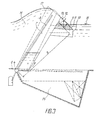
- the hinged closure is arranged in a passage opening 1 (Fig.1) and consists of several sections across the width of the passage opening 1, each of which comprises a separate water baffle 2.
- Each water baffle 2 is connected on its base 3 (FIG. 2) with the aid of a horizontally arranged axis 4 with an immovable support, specifically with a weir base 5, and can be pivoted out about said axis 4.
- An opening 6 is made in the base area 3, via which the interior 7 of the closure communicates with the surrounding medium.
- the closure has a means for supplying compressed air into the interior 7 of the water accumulator body 2 with any generally known construction, which comprises a (not shown) source of compressed air which is connected to the interior 7 via a pipeline 8.
- a container 10 is rigidly attached, for example welded, to the water damming body 2 on its pressure-free side (on the underwater side 9), which is divided into two cells by a horizontal partition 11, of which the upper cell 12 a buoyancy cell and the lower cell 13 is filled with water and constitutes a ballast cell.
- the buoyancy cell 12 can be filled with any substance whose specific weight is far below the specific water weight, for example with foam polystyrene.
- the ballast cell 13 can be filled not only with water, but also with another medium, the specific weight of which is close to the specific water weight.
- the buoyancy cell 12 and the ballast cell 13 together form the means for reducing the vibration of the water accumulation body 2.
- the capacity of the cells 12, 13, substances with which these cells are filled, and the distances between their centers of gravity from the water accumulation body 2 are calculated using known methods, one of which is the condition of a compactness of the water accumulation body 2, which is expedient so that dimensions of a recess 14 in the weir sole for accommodating the water accumulation body 2 are kept as small as possible, and on the other hand is based on the condition that restoring force moments are to be generated, which effectively prevent the water dam 2 from rocking.
- the buoyancy of the buoyancy cell 12 should be so great that no full immersion of the water accumulation body 2 is prevented when its interior 7 is completely filled with water.
- the horizontal partition 11, which divides the container 10 into two cells 12 and 13, is approximately at the level of the water level 15 of the underwater 9 when the water dam 2 is in the predetermined operating position at the maximum water level gradient between the headwater 16 and the underwater 9 .
- a distance of this partition 11 from said water level 15 is to be dimensioned such that an alternating immersion of the buoyancy cell 12 and an emergence of the ballast cell 13 are ensured when the water accumulation body 2 swings.
- the means for reducing the vibration of the water accumulation body 2 can not be considered a through the partition 11 into the cells 12 and 13 divided container 10 are carried out, but have a different construction, which consists for example of a separate buoyancy means and a separate ballast.
- the buoyancy means and / or the ballast can be designed as a whole with the water accumulation body.
- the flip lock works as follows.
- each water dam 2 (FIG. 2) floats by pivoting about the axis 4.
- the buoyancy cell 12 makes it easier for the water accumulation body 2 to emerge at the beginning when it is still in the horizontal position and the air supplied is distributed over the entire surface of the water accumulation body 2 in the interior 7. If the water damming body 2 is in the predetermined operating position at the maximum water level gradient between the upper water 16 and the lower water 9, 16 waves roll onto it from the side of the upper water during a wind wave. If a wave crest 17 (FIG.
- Vibration reduction of the water accumulation bodies 2 of the closure has the consequence that the angles between two adjacent water accumulation bodies 2 are significantly reduced during their deflections from operating positions which are caused by wave energy, as a result of which gaps are reduced or disappear at all, causing water from the upper position 16 flows into the lower position 9.
- the closure is lowered into the recess 14 in the weir base 5 when there is no water gradient between the upper water 16 and the lower water 9. So that the closure is lowered, air is let into the atmosphere from the interior 7 escape, whereby water from the port area penetrates into this interior 7 through an opening, the water dam 2 swings about its axis 4 and lowers into the niche 14.
Landscapes
- Engineering & Computer Science (AREA)
- Structural Engineering (AREA)
- General Engineering & Computer Science (AREA)
- Mechanical Engineering (AREA)
- Civil Engineering (AREA)
- Revetment (AREA)
Applications Claiming Priority (2)
| Application Number | Priority Date | Filing Date | Title |
|---|---|---|---|
| SU4790517 | 1990-02-21 | ||
| SU4790517 | 1990-02-21 |
Publications (1)
| Publication Number | Publication Date |
|---|---|
| EP0443105A1 true EP0443105A1 (fr) | 1991-08-28 |
Family
ID=21495758
Family Applications (1)
| Application Number | Title | Priority Date | Filing Date |
|---|---|---|---|
| EP90121844A Withdrawn EP0443105A1 (fr) | 1990-02-21 | 1990-11-15 | Porte pivotante d'un barrage hydro-technique |
Country Status (1)
| Country | Link |
|---|---|
| EP (1) | EP0443105A1 (fr) |
Cited By (1)
| Publication number | Priority date | Publication date | Assignee | Title |
|---|---|---|---|---|
| AT404268B (de) * | 1996-06-10 | 1998-10-27 | Falkinger Walter Ing | Schwimmwehr |
Citations (4)
| Publication number | Priority date | Publication date | Assignee | Title |
|---|---|---|---|---|
| FR859954A (fr) * | 1939-06-08 | 1941-01-03 | Neyret Beylier & Piccard Picte | Vanne à marée |
| FR1183891A (fr) * | 1957-10-04 | 1959-07-15 | Digues-clapets | |
| DE1634016A1 (de) * | 1967-05-02 | 1971-02-25 | Krupp Gmbh | Schwimmtor fuer Schleusen od.dgl. |
| JPS58143008A (ja) * | 1982-02-18 | 1983-08-25 | Mitsubishi Heavy Ind Ltd | バラストタンク付き水門扉 |
-
1990
- 1990-11-15 EP EP90121844A patent/EP0443105A1/fr not_active Withdrawn
Patent Citations (4)
| Publication number | Priority date | Publication date | Assignee | Title |
|---|---|---|---|---|
| FR859954A (fr) * | 1939-06-08 | 1941-01-03 | Neyret Beylier & Piccard Picte | Vanne à marée |
| FR1183891A (fr) * | 1957-10-04 | 1959-07-15 | Digues-clapets | |
| DE1634016A1 (de) * | 1967-05-02 | 1971-02-25 | Krupp Gmbh | Schwimmtor fuer Schleusen od.dgl. |
| JPS58143008A (ja) * | 1982-02-18 | 1983-08-25 | Mitsubishi Heavy Ind Ltd | バラストタンク付き水門扉 |
Non-Patent Citations (1)
| Title |
|---|
| PATENT ABSTRACTS OF JAPAN vol. 7, no. 261 (M-257)(1406) 19. November 1983 & JP-A-58 143 008 (MITSUBISHI JUKOGYO K.K. ) 25. August 1983 * |
Cited By (1)
| Publication number | Priority date | Publication date | Assignee | Title |
|---|---|---|---|---|
| AT404268B (de) * | 1996-06-10 | 1998-10-27 | Falkinger Walter Ing | Schwimmwehr |
Similar Documents
| Publication | Publication Date | Title |
|---|---|---|
| DE69101309T2 (de) | Überlaufschwelle für aussergewöhnliche Hochwässer für Dämme mit mindestens zwei Überlaufschwellen. | |
| DE3013136C2 (fr) | ||
| DE2716554A1 (de) | Zusammenfallbare und ausdehnbare sperre, beispielsweise fuer einen wasserweg | |
| DE2538990A1 (de) | Wasserfahrzeug zum zusammenraffen und einsammeln schwimmenden treibgutes | |
| DE2718991A1 (de) | Steuerbares bzw. einstellbares wehr | |
| DE2053974A1 (de) | Schwimmfähige Arbeitsplattform | |
| DE3305409A1 (de) | Regenabschlagwerk | |
| DE102013210341A1 (de) | Abdichtungssystem | |
| DE2838431C2 (de) | Klapptor zum Sperren von Flüssen, Kanälen, Docks u.ä | |
| EP0443105A1 (fr) | Porte pivotante d'un barrage hydro-technique | |
| DE3808575A1 (de) | Vorrichtung zum abschotten eines raumes | |
| WO2010115918A2 (fr) | Dispositif non destructif pour générer de l'énergie à partir de vagues | |
| DE3241595A1 (de) | Schwimmender ueberlauf zum ableiten von fluessigkeiten aus einem becken, insbesondere zum ableiten von gereinigtem abwasser aus einem klaerbecken | |
| DE1634156B2 (de) | Vorrichtung zum aufbringen einer schicht aus bituminoesem material auf den boden unter wasser | |
| DE2757704A1 (de) | Gewaessersperre, insbesondere hochwassersperre | |
| DE20300565U1 (de) | Hochwasserschutzeinrichtung | |
| AT314434B (de) | Klappschleuse für die vorübergehende Sperrung von Zugängen zu Innengewässern beim ansteigenden Wasserspiegel des Außenwassers | |
| DE811100C (de) | Verfahren und Einrichtung zum Einsetzen eines Notverschlusses fuer wasserbauliche Anlagen | |
| DE3502243A1 (de) | Vorrichtung zum verschliessen von gewaessern | |
| EP0443095A1 (fr) | Barrage hydro-technique | |
| BE1031856B1 (de) | Ökologische uferschutzstruktur auf der basis poröser steinblöcke | |
| DE4301137C1 (de) | Stauklappenwehr | |
| DE3106199A1 (de) | Verstellbare unterstuetzung einer unterwasserrohrleitung | |
| DE3153005T1 (de) | Vorrichtung zum Entfernen von Öl und Unrat vom Wasser | |
| DE2555523C3 (de) | Einrichtung zum Absperren von Stollen, insbesondere des Saugrohres einer Wasserkraftanlage |
Legal Events
| Date | Code | Title | Description |
|---|---|---|---|
| PUAI | Public reference made under article 153(3) epc to a published international application that has entered the european phase |
Free format text: ORIGINAL CODE: 0009012 |
|
| AK | Designated contracting states |
Kind code of ref document: A1 Designated state(s): BE DE FR GB IT NL |
|
| STAA | Information on the status of an ep patent application or granted ep patent |
Free format text: STATUS: THE APPLICATION IS DEEMED TO BE WITHDRAWN |
|
| 18D | Application deemed to be withdrawn |
Effective date: 19920229 |