EP0443181A1 - Soupape papillon - Google Patents
Soupape papillon Download PDFInfo
- Publication number
- EP0443181A1 EP0443181A1 EP90125019A EP90125019A EP0443181A1 EP 0443181 A1 EP0443181 A1 EP 0443181A1 EP 90125019 A EP90125019 A EP 90125019A EP 90125019 A EP90125019 A EP 90125019A EP 0443181 A1 EP0443181 A1 EP 0443181A1
- Authority
- EP
- European Patent Office
- Prior art keywords
- valve
- airfoil
- torque
- flow
- passage
- Prior art date
- Legal status (The legal status is an assumption and is not a legal conclusion. Google has not performed a legal analysis and makes no representation as to the accuracy of the status listed.)
- Granted
Links
Images


Classifications
-
- F—MECHANICAL ENGINEERING; LIGHTING; HEATING; WEAPONS; BLASTING
- F02—COMBUSTION ENGINES; HOT-GAS OR COMBUSTION-PRODUCT ENGINE PLANTS
- F02M—SUPPLYING COMBUSTION ENGINES IN GENERAL WITH COMBUSTIBLE MIXTURES OR CONSTITUENTS THEREOF
- F02M7/00—Carburettors with means for influencing, e.g. enriching or keeping constant, fuel/air ratio of charge under varying conditions
-
- F—MECHANICAL ENGINEERING; LIGHTING; HEATING; WEAPONS; BLASTING
- F02—COMBUSTION ENGINES; HOT-GAS OR COMBUSTION-PRODUCT ENGINE PLANTS
- F02D—CONTROLLING COMBUSTION ENGINES
- F02D9/00—Controlling engines by throttling air or fuel-and-air induction conduits or exhaust conduits
- F02D9/08—Throttle valves specially adapted therefor; Arrangements of such valves in conduits
- F02D9/10—Throttle valves specially adapted therefor; Arrangements of such valves in conduits having pivotally-mounted flaps
- F02D9/1005—Details of the flap
- F02D9/101—Special flap shapes, ribs, bores or the like
-
- F—MECHANICAL ENGINEERING; LIGHTING; HEATING; WEAPONS; BLASTING
- F02—COMBUSTION ENGINES; HOT-GAS OR COMBUSTION-PRODUCT ENGINE PLANTS
- F02D—CONTROLLING COMBUSTION ENGINES
- F02D9/00—Controlling engines by throttling air or fuel-and-air induction conduits or exhaust conduits
- F02D9/08—Throttle valves specially adapted therefor; Arrangements of such valves in conduits
- F02D9/10—Throttle valves specially adapted therefor; Arrangements of such valves in conduits having pivotally-mounted flaps
-
- F—MECHANICAL ENGINEERING; LIGHTING; HEATING; WEAPONS; BLASTING
- F16—ENGINEERING ELEMENTS AND UNITS; GENERAL MEASURES FOR PRODUCING AND MAINTAINING EFFECTIVE FUNCTIONING OF MACHINES OR INSTALLATIONS; THERMAL INSULATION IN GENERAL
- F16K—VALVES; TAPS; COCKS; ACTUATING-FLOATS; DEVICES FOR VENTING OR AERATING
- F16K1/00—Lift valves or globe valves, i.e. cut-off apparatus with closure members having at least a component of their opening and closing motion perpendicular to the closing faces
- F16K1/16—Lift valves or globe valves, i.e. cut-off apparatus with closure members having at least a component of their opening and closing motion perpendicular to the closing faces with pivoted closure-members
- F16K1/18—Lift valves or globe valves, i.e. cut-off apparatus with closure members having at least a component of their opening and closing motion perpendicular to the closing faces with pivoted closure-members with pivoted discs or flaps
- F16K1/22—Lift valves or globe valves, i.e. cut-off apparatus with closure members having at least a component of their opening and closing motion perpendicular to the closing faces with pivoted closure-members with pivoted discs or flaps with axis of rotation crossing the valve member, e.g. butterfly valves
- F16K1/222—Shaping of the valve member
Definitions
- the present invention relates to a rotary valve widely used to open and close a flow passage or control the flow rate at an intermediate position of the passage of the air supply system of an automobile engine, an air-conditioning equipment, plant pipeline, or an evacuating apparatus.
- a rotary valve is utilized as the air feeding throttle valve of the automobile engine because it has a simple construction and adjusts flow rate easily.
- the throttle valve is mechanically interlocked with an accelerator stepped by a driver. That is, the force generated by the driver's stepping of the accelerator is directly transmitted to the valve.
- the force necessary for operating the valve is much smaller than the force required for the driver to step the accelerator. Therefore, there is no difficulty in operating the valve.
- the inventors aim to improve the torque to be applied to the valve. In order to achieve the aim, they tried to allow the valve which is driven by a servo motor and the entire control system thereof to have a high performance and be miniaturized. Many people have reported their theoretical and experimental investigations regarding the characteristic of the throttle valve (generally called butterfly valve).
- Mr. M. J. Morris. et al. made a series of experiments to analyze unbalanced aerodynamic torque applied to the valve in their thesis "Peak torque characteristics of butterfly valves, American Society of Mechanical Engineers FED Vol. 54, P63 - 66, 1987". They measured static pressure applied to a valve disk and found the torque characteristic that torque increases to a maximum at a certain intermediate valve disk angle.
- Mr. Kato et al. analyzed the characteristic of torque applied to the valve utilizing a computer simulation.
- their report “On the numerical analysis of characteristics for two dimensional model of butterfly valves” (Research Report No. 55, 1983, Kogakuin University), they performed numerical calculations solving a simultaneous equation consisting of the equation of Navie-Storks and an equation of continuity in an aerodynamic flow. They found flow condition, flow speed, and pressure distribution to make an analysis including the torque characteristic of a valve.
- a desirable flow rate can be obtained by the butterfly valve when it is positioned at a predetermined angle in a flow with high speed and accuracy. If a great torque (unbalanced torque) is applied by fluid resistance to the valve which imposes a load on the motor and if the torque is greatly dependent on the valve disk angle, a great torque is a big obstacle in achieving a stabilized control system.
- Apparatuses of an automobile are required to be compact and simple in construction due to its limited space and power supply. Therefore, it is difficult for a compact electric motor having a limited power to rotate the valve disk with a high response and accuracy against a big unbalanced torque applied to the valve.
- Fig. 13 shows the construction of a conventional rotary valve comprising a valve shaft 2 rotatably mounted at a certain position of a flow passage 1 and flat airfoils 3 and 4 mounted on either side of the shaft 2.
- the arrow at the left end shows the flow direction.
- the passage 1 is closed with the flat airfoils 3 and 4 perpendicular to the flow direction, the flow is interrupted.
- the airfoils 3 and 4 rotate clockwise, the valve is opened.
- the analysis of the flow in the vicinity of the conventional valve of the above construction has been conducted. The condition under which the analysis has been made is described later.
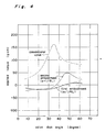
- the relationship between the valve disk angle ⁇ and torque T is shown by the chain line of Fig. 4. As shown by the graph, torque T has a peak value when the angle ⁇ which the airfoils 3 and 4 make with the vertical line is in the vicinity of 35°.
- the problem that the rotary valve is subjected to a big torque due to fluid resistance occurs not only in the air feed throttle valve for use in an automobile, but also in an electric actuator-driven butterfly valve for use in plants.
- a rotary valve comprising: a first airfoil moving downstream when the valve is opened; a second airfoil moving upstream when the valve is opened; a valve body including the first and second airfoils; a shaft for supporting the valve body; and a passage for rotatably accommodating the valve body through the shaft and guiding a fluid, wherein the first airfoil is concaved and/or the second airfoil is convexed.
- FIG. 1A is a model view showing the valve of one of the aspects of the present invention
- Fig. 1B which is a model view showing the conventional art
- the valve comprising a valve shaft 100, a first airfoil 101, and a second airfoil 102 is accommodated in a flow passage 103.
- a nozzle between the end of the first airfoil 101 and the wall of the passage 103 and a nozzle between the end of the second airfoil 102 and the wall of the passage 103 are denoted as a first gap 104 and a second gap 105, respectively.
- the direction of the stream B' is changed greatly in the vicinity of the end of the upper surface of the second airfoil 102, and then the stream B' progresses toward the second gap 105. Therefore, the velocity of the fluid flowing along the upper surface of the second airfoil 102 is small. From Bernoulli's theorem, where U is velocity of fluid; P is static pressure, and ⁇ is density of fluid. Accordingly, in the upstream side of the valve, the static pressure P over the first airfoil 101 is low because the flow velocity U is high there while the static pressure P over the second airfoil 102 is high because the flow velocity is low.
- a lift is generated in the periphery of the wings of an airplane by the static pressure difference between the flow velocity above and below the wing.
- a moment in the valve-closing direction is generated about the shaft 100 by the difference of the static pressures of the airfoils, that is, the difference between the flow velocity above the upper surface of the first airfoil 101 and that above the upper surface of the second airfoil 102.
- the valve according to one of the aspects of the present invention comprises a valve shaft 200, a concaved first airfoil 201 and a convexed second airfoil 202.
- a nozzle between the end of the first airfoil 201 and the wall of a flow passage 203 and a nozzle between the end of the second airfoil 202 and the wall of the passage 203 are denoted as a first gap 204 and a second gap 205, respectively.
- the flow is separated into two streams A and B in the upstream side of the valve, and the streams A and B flow toward the first and second gaps 204 and 205, respectively.
- the stream A flows along the upper surface of the first airfoil 201 toward the first gap 204 in the condition in which the first airfoil 201 forms an obtuse angle with the wall of the passage 203. Therefore, the velocity of the stream A is low, i.e., the static pressure becomes maximum, thus approaching zero at the bottom thereof just like a cavity over which wind is blowing.
- the stream B flows along the upper surface of the second airfoil 202 toward the first gap 205 in the condition in which the second airfoil 202 forms an acute angle with the wall of the passage 203.
- the flow velocity of the stream B becomes maximum at the top point of the convexed second airfoil while the static pressure is minimum there.
- a moment in the valve-opening direction is generated by the increase of the static pressure along the upper surface of the first airfoil 201 and the fall of the static pressure along the upper surface of the second airfoil 202 as shown by the arrow C of Fig. 1A.
- the feature of the valve according to the aspect of the present invention is that the difference in the static pressures along the upper surface of the first and second airfoils 201 and 202 is reduced by providing the valve having airfoils curved to satisfy the following condition.
- a concave or convex surface formed only on the first or second airfoil is capable of reducibly applying torque to the valve because a moment is generated in a valve-opening direction opposed to the direction of the moment generated according to the conventional valve.
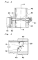
- Fig. 2 is a sectional view of a rotary valve
- Fig. 3 is a sectional view taken along the line A-A of Fig. 2.
- a valve comprising a shaft 10, a first airfoil 20, and a second airfoil 30 is mounted on the center of a flow passage 40 serving as an air intake cylinder.
- Reference numerals 50 and 60 shown in Fig. 3 denote a first gap and a second gap. Fluid flows in the direction shown by the arrow shown in the left end of Fig. 3.
- the shaft 10 is driven by a motor 70 through gears 80 and 90.
- a return spring 91 mounted on the right end of the shaft 10 urges the shaft 10 so that the return spring 91 closes the valve in emergency.
- valve body comprising the first and second airfoils 20 and 30 are perpendicular to the passage 40, the valve is closed. With the clockwise rotation of the first and second airfoils 20 and 30, the valve is opened.
- This basic construction is similar to that of the conventional rotary valve.
- torque to be applied to the rotating valve body by a fluid in opening the valve can be reduced because of an improved sectional configuration of the first and second airfoils 20 and 30.
- the first and second airfoils 20 and 30 are sine-curved. Therefore, the valve is approximately in the shape of an inverted S.
- the mechanism of the valve capable of reducing torque has been numerically analyzed for a planar two-dimensional throttle valve model in comparison with the conventional valve.
- the opposing walls of the passage are parallel with each other. The condition is as follows on the assumption that the valve is mounted on an automobile.
- Fig. 4 shows the relationship between applied torque T and valve disk angle ⁇ obtained by the analysis of static pressure around the valve performed on the valve comprising the first and second airfoils 20 and 30 according to the first embodiment.
- the a 1 ⁇ 4 L, where a is the length corresponding to the wave crest of the sine curve, and L is the length corresponding to the length of the straight line between the shaft 10 and the end of the first and second airfoils 20 and 30.
- Fig. 4 also shows the result obtained by analyzing applied torque characteristic of the conventional valve in the above-described conditions 1 through 4 described previously.
- the dynamic pressure applied to the first airfoil 101 of the embodiment is smaller than that applied to the first airfoil 201 of the conventional valve whereas the static pressure applied to the former is larger than that applied to the latter.
- the dynamic pressure applied to the second airfoil 205 of the embodiment is larger than that applied to the second airfoil 205 of the conventional valve whereas the static pressure applied to the former is smaller than that applied to the latter. Consequently, the torque can be applied to the valve of the embodiment in a reduced amount. As understood from the velocity diagram shown in Figs.
- velocity vectors are varied from each other depending on a place whereas in the downstream side of the flow, velocity vectors are not varied greatly from each other. This fact indicates that the main factor which decides torque depends mainly on the configuration of the airfoil in the upstream side.
- the flow rate of the second gap is larger than that of the first gap.
- Fig. 7 shows the pressure difference over the airfoils between the valve of the present and the conventional valve.
- x-coordinate is taken along the airfoil surface, the position of the shaft is zero in x-direction, and x-direction toward the first gap 50 is the positive side.
- the ordinate axis is the pressure difference ⁇ P between the upstream side and the downstream side of the airfoil.
- the abscissa axis is x L and non-dimensional where L is the length corresponding to the length of the straight line between the shaft 10 and the end of the first and second airfoils 20 and 30.
- the pressure difference ⁇ P is minimum in the end of the first airfoil and maximum in the end of the second airfoil as shown by the chain line of Fig. 7. As shown in the graph, an unbalanced pressure is applied to the conventional valve about the shaft thereof.
- This phenomenon is caused by the fact that the fluid flows along the upper surface of the first airfoil which forms an obtuse angle with the wall of the passage. Therefore, the static pressure above the first airfoil is maximum.
- the fluid flows along the upper surface of the second airfoil which forms an acute angle with the wall of the passage. Therefore, the static pressure above the second airfoil is minimum as described previously.
- the valve of the embodiment is in an inverted S configuration, however, this depends on a direction in which the valve is viewed. If the valve is viewed from the backside of the drawing sheet of Fig. 3, the configuration of the valve is S-shaped.
- Fig. 4 shows by one-dot chain line the torque characteristic of the valve of the second embodiment in which the length (a) is one eighth of the length L of the airfoil.
- the torque T applied to the valve of the second embodiment is smaller than that of the conventional valve. Since the torque T becomes greater with the increase of the valve disk angle ⁇ , it is preferable to use the valve at a small angle.
- the first and second airfoils 20 and 30 can be embodied in the following configurations.
- they are convexed smoothly along flow, i.e., preferably, they are smoothly curved like a sine curve or a circular arc as shown in Fig. 3. But they can be V-shaped as shown in Fig. 8.
- the airfoil is also formed to be quadrangular, and the fluid flows only along the passage. Therefore, the assumption based on the numerical analysis of a two-dimensional fluid made with reference to Fig. 6 generally coincides with the actual flow direction.
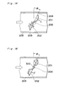
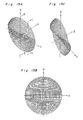
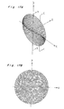
- a flow occurs in the direction perpendicular to the sheet showing Fig. 14, which is not considered by two-dimension analysis.
- the fluid flows downstream between the end of the first airfoil 201 and the wall of the passage and between the end of the second airfoil 202 and the wall of the passage as shown by the arrows C and D.
- the flow perpendicular to the sheet is not a flow along the concaved and convexed surface of the airfoils.
- the feature of the present invention is based on the theoretical ground that the airfoils have the configuration to satisfy the following:
- Fig. 16 which is a sectional view of the valve of Fig. 15, the fluid flows along the end portion of the first and second airfoils 201 and 202, and in C' and D' directions, but the speed of each flow is not as high as that of the flow which occurs in such a configuration which is curved only in the flow direction as described in the above item (I).
- the fluid flows both along the upper surface of the first airfoil which forms an obtuse angle with the wall of the passage and along the upper surface of the second airfoil which forms an acute angle with the wall of the passage.
- the valve of Fig. 15 has the effect of the present invention. That is, the torque can be greatly reduced.
- the flat portion is provided in the center of the valve to fasten the first and second airfoils 201 and 202 to the shaft 200 with bolts through holes 207 in Fig. 15F.
- Fig. 17 shows a valve not having a flat portion in the center thereof. According to this configuration, the inclination of the airfoil with respect to Z-axis is varied depending on a position along x-axis. Therefore, it is difficult to fix the airfoils to the shaft.
- both the first and second airfoils 20 and 30 are symmetrical with respect to the shaft.
- the present invention can be embodied by modifying the curved configuration of the first and second airfoils 20 and 30 and curvature thereof. Torque can be applied to the valve in a varied manner by making the first and second airfoils 20 and 30 asymmetrical with respect to the shaft 10.
- first airfoil 20 is concaved in the flowing direction of the fluid while the second airfoil 30 remains flat.
- the second airfoil 30 is convexed in the flowing direction of the fluid while the first airfoil 20 is flat.
- the configuration of the passage 40 can be altered to change the direction of the flow in the vicinity of the airfoils 20 and 30.
- torque can be applied to the valve in a reduced amount although the valve is not shown in the drawings.
- the valve according to the present invention can be used not only as an air feeding throttle valve for use in an automobile engine, but also as a flow rate control butterfly valve for use in an air-conditioning plant and a chemical plant, a vacuum pressure control valve for use in a vacuum equipment.
- the airfoil of the valve according to the present invention is capable of reducing torque.
- the airfoil has either of the following configurations:
- Static pressure is applied to the upper and lower airfoils in a balanced condition by adopting either the configuration of the above item 1 or 2 or both items 1 and 2.
- torque is reducibly applied to the valve.
- a larger diameter valve than the conventional one can be mounted on an equipment because of the following reason.
- a throttle valve reduces the ratio of resistance to inhaled air as greatly as possible. Therefore, the use of a large diameter valve is desired.
- torque is applied to the valve in proportion to the cube of a valve diameter. Therefore, there is a limitation to the increase of the inner diameter of a flow passage.
- a control system can be constructed with a small electric actuator comprising the valve of the present invention.
- valve of present invention enables an electronic control of the flow rate.
Landscapes
- Engineering & Computer Science (AREA)
- General Engineering & Computer Science (AREA)
- Mechanical Engineering (AREA)
- Chemical & Material Sciences (AREA)
- Combustion & Propulsion (AREA)
- Lift Valve (AREA)
- Valve Housings (AREA)
- Check Valves (AREA)
Applications Claiming Priority (4)
| Application Number | Priority Date | Filing Date | Title |
|---|---|---|---|
| JP1335613A JPH03194135A (ja) | 1989-12-25 | 1989-12-25 | 回動板式弁 |
| JP335613/89 | 1989-12-25 | ||
| JP60181/90 | 1990-03-12 | ||
| JP6018190 | 1990-03-12 |
Publications (2)
| Publication Number | Publication Date |
|---|---|
| EP0443181A1 true EP0443181A1 (fr) | 1991-08-28 |
| EP0443181B1 EP0443181B1 (fr) | 1997-05-14 |
Family
ID=26401248
Family Applications (1)
| Application Number | Title | Priority Date | Filing Date |
|---|---|---|---|
| EP90125019A Expired - Lifetime EP0443181B1 (fr) | 1989-12-25 | 1990-12-20 | Soupape papillon |
Country Status (3)
| Country | Link |
|---|---|
| EP (1) | EP0443181B1 (fr) |
| KR (1) | KR950000605B1 (fr) |
| DE (1) | DE69030720T2 (fr) |
Cited By (6)
| Publication number | Priority date | Publication date | Assignee | Title |
|---|---|---|---|---|
| EP0503492A3 (en) * | 1991-03-08 | 1992-12-02 | Matsushita Electric Industrial Co., Ltd. | Rotary valve |
| EP0721059A3 (fr) * | 1995-01-09 | 1997-02-12 | Toyota Motor Co Ltd | Vanne papillon |
| EP1319817A1 (fr) * | 2001-12-17 | 2003-06-18 | Delphi Technologies, Inc. | Soupape à clapet pour un passage d'écoulement d'un fluide |
| WO2008058779A1 (fr) * | 2006-11-16 | 2008-05-22 | Pierburg Gmbh | Dispositif de régulation pour un moteur à combustion interne |
| EP2037101A1 (fr) * | 2007-09-13 | 2009-03-18 | Magneti Marelli Powertrain S.p.A. | Papillon des gaz pour moteur à combustion interne |
| CN102644513A (zh) * | 2012-05-12 | 2012-08-22 | 中国兵器工业集团第七0研究所 | 一种发动机节气门蝶阀 |
Families Citing this family (1)
| Publication number | Priority date | Publication date | Assignee | Title |
|---|---|---|---|---|
| US9897214B2 (en) | 2015-11-04 | 2018-02-20 | Honeywell International Inc. | Off-set and sine-wave shaped butterfly plate to reduce aero-torque and reduce actuator size |
Citations (7)
| Publication number | Priority date | Publication date | Assignee | Title |
|---|---|---|---|---|
| US2010694A (en) * | 1934-07-16 | 1935-08-06 | A D Macdonell | Air feed control means |
| US2095263A (en) * | 1936-04-25 | 1937-10-12 | Gen Electric | Butterfly valve |
| US3516640A (en) * | 1967-09-06 | 1970-06-23 | Nat Res Dev | Butterfly valve |
| US3677297A (en) * | 1969-09-22 | 1972-07-18 | Serck Industries Ltd | Butterfly valves |
| GB1423335A (en) * | 1973-10-09 | 1976-02-04 | Cafe Bar Internal Pty Ltd | Butterfly valves |
| US3960177A (en) * | 1975-03-12 | 1976-06-01 | Baumann Hans D | Low torque and low noise butterfly valve disc |
| US4275867A (en) * | 1977-03-17 | 1981-06-30 | Keystone International, Inc. | Valve assembly and method |
-
1990
- 1990-12-20 DE DE69030720T patent/DE69030720T2/de not_active Expired - Fee Related
- 1990-12-20 EP EP90125019A patent/EP0443181B1/fr not_active Expired - Lifetime
- 1990-12-24 KR KR1019900021658A patent/KR950000605B1/ko not_active Expired - Fee Related
Patent Citations (7)
| Publication number | Priority date | Publication date | Assignee | Title |
|---|---|---|---|---|
| US2010694A (en) * | 1934-07-16 | 1935-08-06 | A D Macdonell | Air feed control means |
| US2095263A (en) * | 1936-04-25 | 1937-10-12 | Gen Electric | Butterfly valve |
| US3516640A (en) * | 1967-09-06 | 1970-06-23 | Nat Res Dev | Butterfly valve |
| US3677297A (en) * | 1969-09-22 | 1972-07-18 | Serck Industries Ltd | Butterfly valves |
| GB1423335A (en) * | 1973-10-09 | 1976-02-04 | Cafe Bar Internal Pty Ltd | Butterfly valves |
| US3960177A (en) * | 1975-03-12 | 1976-06-01 | Baumann Hans D | Low torque and low noise butterfly valve disc |
| US4275867A (en) * | 1977-03-17 | 1981-06-30 | Keystone International, Inc. | Valve assembly and method |
Cited By (6)
| Publication number | Priority date | Publication date | Assignee | Title |
|---|---|---|---|---|
| EP0503492A3 (en) * | 1991-03-08 | 1992-12-02 | Matsushita Electric Industrial Co., Ltd. | Rotary valve |
| EP0721059A3 (fr) * | 1995-01-09 | 1997-02-12 | Toyota Motor Co Ltd | Vanne papillon |
| EP1319817A1 (fr) * | 2001-12-17 | 2003-06-18 | Delphi Technologies, Inc. | Soupape à clapet pour un passage d'écoulement d'un fluide |
| WO2008058779A1 (fr) * | 2006-11-16 | 2008-05-22 | Pierburg Gmbh | Dispositif de régulation pour un moteur à combustion interne |
| EP2037101A1 (fr) * | 2007-09-13 | 2009-03-18 | Magneti Marelli Powertrain S.p.A. | Papillon des gaz pour moteur à combustion interne |
| CN102644513A (zh) * | 2012-05-12 | 2012-08-22 | 中国兵器工业集团第七0研究所 | 一种发动机节气门蝶阀 |
Also Published As
| Publication number | Publication date |
|---|---|
| EP0443181B1 (fr) | 1997-05-14 |
| DE69030720T2 (de) | 1997-09-04 |
| KR910012516A (ko) | 1991-08-08 |
| KR950000605B1 (ko) | 1995-01-26 |
| DE69030720D1 (de) | 1997-06-19 |
Similar Documents
| Publication | Publication Date | Title |
|---|---|---|
| US6808162B2 (en) | Rotary 2-way servovalve | |
| US5771929A (en) | Low noise ball valve assembly with airfoil insert | |
| US6016832A (en) | Valve for controlling gas mass flow | |
| EP0443181A1 (fr) | Soupape papillon | |
| US3981283A (en) | Engine exhaust gas recirculating control | |
| US10544879B2 (en) | Sonic flow control valve | |
| CA1235616A (fr) | Regulateur de regime de ralenti | |
| CN118090125B (zh) | 一种吹气襟翼式高速风洞阵风发生器及发生方法 | |
| JPH0574692B2 (fr) | ||
| JPH04214936A (ja) | 回動板式弁 | |
| EP0503492A2 (fr) | Vanne papillon | |
| Luo et al. | The mechanism of jet vectoring using synthetic jet actuators | |
| JPS6229723A (ja) | タ−ボ過給機 | |
| US4450807A (en) | Suction air throttling device of diesel engine | |
| JPS6388221A (ja) | 排気タ−ビン過給機 | |
| EP0076612A1 (fr) | Obturateur d'étranglement | |
| JPH03194135A (ja) | 回動板式弁 | |
| JPH064031Y2 (ja) | 吸気制御弁装置 | |
| CN215673626U (zh) | 一种电动微调高真空挡板阀 | |
| JPS6158923A (ja) | タ−ボチヤ−ジヤのサ−ジ防止装置 | |
| JPS6032353Y2 (ja) | 過給機付エンジンの吸気装置 | |
| CN2234080Y (zh) | 流量计的盒式芯子 | |
| JP2007321635A (ja) | 内燃機関の吸気制御装置 | |
| JP3460137B2 (ja) | 気化器の減速装置 | |
| JPS63302168A (ja) | 可変ベンチユリ式気化器の可動弁 |
Legal Events
| Date | Code | Title | Description |
|---|---|---|---|
| PUAI | Public reference made under article 153(3) epc to a published international application that has entered the european phase |
Free format text: ORIGINAL CODE: 0009012 |
|
| 17P | Request for examination filed |
Effective date: 19901220 |
|
| AK | Designated contracting states |
Kind code of ref document: A1 Designated state(s): DE FR GB |
|
| 17Q | First examination report despatched |
Effective date: 19931005 |
|
| GRAG | Despatch of communication of intention to grant |
Free format text: ORIGINAL CODE: EPIDOS AGRA |
|
| GRAH | Despatch of communication of intention to grant a patent |
Free format text: ORIGINAL CODE: EPIDOS IGRA |
|
| GRAH | Despatch of communication of intention to grant a patent |
Free format text: ORIGINAL CODE: EPIDOS IGRA |
|
| GRAA | (expected) grant |
Free format text: ORIGINAL CODE: 0009210 |
|
| AK | Designated contracting states |
Kind code of ref document: B1 Designated state(s): DE FR GB |
|
| REF | Corresponds to: |
Ref document number: 69030720 Country of ref document: DE Date of ref document: 19970619 |
|
| ET | Fr: translation filed | ||
| PLBE | No opposition filed within time limit |
Free format text: ORIGINAL CODE: 0009261 |
|
| STAA | Information on the status of an ep patent application or granted ep patent |
Free format text: STATUS: NO OPPOSITION FILED WITHIN TIME LIMIT |
|
| 26N | No opposition filed | ||
| PGFP | Annual fee paid to national office [announced via postgrant information from national office to epo] |
Ref country code: FR Payment date: 19981209 Year of fee payment: 9 |
|
| PGFP | Annual fee paid to national office [announced via postgrant information from national office to epo] |
Ref country code: GB Payment date: 19981224 Year of fee payment: 9 |
|
| PGFP | Annual fee paid to national office [announced via postgrant information from national office to epo] |
Ref country code: DE Payment date: 19981229 Year of fee payment: 9 |
|
| PG25 | Lapsed in a contracting state [announced via postgrant information from national office to epo] |
Ref country code: GB Free format text: LAPSE BECAUSE OF NON-PAYMENT OF DUE FEES Effective date: 19991220 |
|
| GBPC | Gb: european patent ceased through non-payment of renewal fee |
Effective date: 19991220 |
|
| PG25 | Lapsed in a contracting state [announced via postgrant information from national office to epo] |
Ref country code: FR Free format text: LAPSE BECAUSE OF NON-PAYMENT OF DUE FEES Effective date: 20000831 |
|
| PG25 | Lapsed in a contracting state [announced via postgrant information from national office to epo] |
Ref country code: DE Free format text: LAPSE BECAUSE OF NON-PAYMENT OF DUE FEES Effective date: 20001003 |
|
| REG | Reference to a national code |
Ref country code: FR Ref legal event code: ST |