EP0443236A1 - Axialmagnetfeld-Vakuumschalter - Google Patents
Axialmagnetfeld-Vakuumschalter Download PDFInfo
- Publication number
- EP0443236A1 EP0443236A1 EP90306838A EP90306838A EP0443236A1 EP 0443236 A1 EP0443236 A1 EP 0443236A1 EP 90306838 A EP90306838 A EP 90306838A EP 90306838 A EP90306838 A EP 90306838A EP 0443236 A1 EP0443236 A1 EP 0443236A1
- Authority
- EP
- European Patent Office
- Prior art keywords
- electrode
- coil conductor
- electrode structure
- main electrode
- main
- Prior art date
- Legal status (The legal status is an assumption and is not a legal conclusion. Google has not performed a legal analysis and makes no representation as to the accuracy of the status listed.)
- Ceased
Links
- 239000004020 conductor Substances 0.000 claims abstract description 110
- RYGMFSIKBFXOCR-UHFFFAOYSA-N Copper Chemical group [Cu] RYGMFSIKBFXOCR-UHFFFAOYSA-N 0.000 claims abstract description 22
- 230000001154 acute effect Effects 0.000 claims 1
- 230000015556 catabolic process Effects 0.000 description 3
- 229910052802 copper Inorganic materials 0.000 description 3
- 239000010949 copper Substances 0.000 description 3
- 239000003989 dielectric material Substances 0.000 description 2
- 230000000694 effects Effects 0.000 description 2
- 230000002093 peripheral effect Effects 0.000 description 2
- 125000006850 spacer group Chemical group 0.000 description 2
- VYZAMTAEIAYCRO-UHFFFAOYSA-N Chromium Chemical compound [Cr] VYZAMTAEIAYCRO-UHFFFAOYSA-N 0.000 description 1
- 230000004323 axial length Effects 0.000 description 1
- 238000010276 construction Methods 0.000 description 1
- 239000000463 material Substances 0.000 description 1
- 238000013021 overheating Methods 0.000 description 1
- 238000004904 shortening Methods 0.000 description 1
- 229910001220 stainless steel Inorganic materials 0.000 description 1
- 239000010935 stainless steel Substances 0.000 description 1
- 238000003466 welding Methods 0.000 description 1
Images



Classifications
-
- H—ELECTRICITY
- H01—ELECTRIC ELEMENTS
- H01H—ELECTRIC SWITCHES; RELAYS; SELECTORS; EMERGENCY PROTECTIVE DEVICES
- H01H33/00—High-tension or heavy-current switches with arc-extinguishing or arc-preventing means
- H01H33/60—Switches wherein the means for extinguishing or preventing the arc do not include separate means for obtaining or increasing flow of arc-extinguishing fluid
- H01H33/66—Vacuum switches
-
- H—ELECTRICITY
- H01—ELECTRIC ELEMENTS
- H01H—ELECTRIC SWITCHES; RELAYS; SELECTORS; EMERGENCY PROTECTIVE DEVICES
- H01H33/00—High-tension or heavy-current switches with arc-extinguishing or arc-preventing means
- H01H33/60—Switches wherein the means for extinguishing or preventing the arc do not include separate means for obtaining or increasing flow of arc-extinguishing fluid
- H01H33/66—Vacuum switches
- H01H33/664—Contacts; Arc-extinguishing means, e.g. arcing rings
- H01H33/6642—Contacts; Arc-extinguishing means, e.g. arcing rings having cup-shaped contacts, the cylindrical wall of which being provided with inclined slits to form a coil
Definitions
- the present invention relates to a vacuum interrupter and more particularly to an improved electrode structure for a vacuum interrupter. Still more particularly, the invention relates to an improved electrical connector and main electrode structure forming a part of the electrodes for a vacuum interrupter.
- a vacuum interrupter for handling a high current generally includes a pair of main electrodes disposed in a vacuum vessel so that at least one of the pair is movable toward and away from the other, coil conductors mounted on the rear surfaces of the main electrodes, and conductor rods extending to the exterior of the vacuum vessel from the rear surfaces of the coil conductors.
- Current flows from one of the conductor rods to the other through the coil conductors and main electrodes.
- one of the conductor rods is urged by an actuator for the purpose of interrupting the current, at least one of the main electrodes is moved away from the other, and an arc current is caused to flow Between the spaced electrodes.
- This arc current is dispersed into a plurality of filament-like arc currents by a magnetic field created by the flow current through the coil conductors.
- Electrical connectors provide a bridge for current flow between the main electrode and the coil conductor.
- the main electrodes When the main electrodes are in the closed position of contact and in contact with each other, current flows through the points of contact between the main electrodes. Thus, current flows through the main electrode between path defined by the electrical connectors and the points of contact. Because the points of contact between the main electrodes varies with the construction of each main electrode, it is impossible to predict the correct path through the main electrode.
- the current will flow through the periphery of the min electrode, when the distance to the electrical connector is shortest and thus where ohmic resistance is lowest.
- the point of contact will be in the middle of the main electrodes, where the distance and the electrical connector is greatest and ohmic resistance consequently is much higher. As resistance increases the likelihood of thermal breakdown also increases. Oftentimes the thermal breakdown results in the main electrodes welding together at their middle. Once the main electrodes weld together, it becomes extremely difficult to separate them.
- U.S. Patent No. 3,946,179 discloses a coil conductor that comprises a plurality of conductive arms connected to arcuate sections.
- the arms connect at one end to a conductor rod and diverge in a generally radial direction therefrom to connect to an arcuate section at the other end.
- the arcuate sections extend circumferentially from the arms and connect to a main electrode.
- Current flows from the rod to the main electrode through the spaced arms and associated arcuate sections.
- the one-turn current produces a uniform axial magnetic field that produces the diffuse, filamentary arc currents between the main electrodes.
- the current will be forced through a region of relatively high resistance, causing the temperature of the main electrode to increase, until thermal breakdown results.
- the main electrodes weld together and cannot be separated.
- a uniform axial magnetic field is maximized, thereby providing an arc current that is more evenly distributed.
- the axial magnetic field is maximized by reducing the radial magnetic field through the use of a uniform cylindrical coil conductor.
- the invention disclosed a structure support rod to reduce mechanical stress.
- current is forced through the points of contact between the main electrodes. As a result, current tends to flow in the center of the main electrodes, thereby increasing the resistance of the main electrodes and shortening the life of the main electrodes.
- the improved vacuum interrupter includes an electrode structure with a main electrode for maintaining a low resistance current path.
- the main electrode has a ring-shaped protrusion on its center side for contacting the opposing main electrode.
- the improved electrode structure also includes a coil conductor for increasing the axial magnetic field within the vacuum vessel.
- a number of electrical connectors extend from the opposing end of the coil conductor for providing current to the main electrode.
- the ring-shaped protrusion on the main electrode provides a contact point in a region that is closest to the electrical connectors.
- a copper ring is interposed between the electrical connector and main electrodes to maintain current at the periphery of the main electrode.
- the coil conductor includes a plurality of inclined slits, at least two, formed on a cylindrical body, defining separate current paths of approximately one-half turn each around the circumference of the cylindrical coil conductor. Current flows axially through an external conductor rod, radially through a conductor disk, and then axially through the coil conductor and the several current paths defined thereon.
- Two substantially identical electrode structures are provided in the vacuum vessel so that the inclined slits on each of the opposing coil conductors are generally parallel.
- current flows from a first external conductor rod, through a first conductor disk, and then through the several current paths defined by the coil conductor to an electrical connector.
- Current flows through the electrical connector to the copper disc to the periphery of the main electrode to the protrusion on the main electrode.
- the current passes from the protrusion on a first main electrode to the protrusion on the opposing electrode structure, which is, in effect, a mirror image of the first electrode structure.
- the slits and current paths on the two opposing conductor coils are aligned such that the current effectively flows through one full turn as it passes through the vacuum vessel.
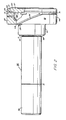
- a vacuum interrupter constructed in accordance with the preferred embodiment of the present invention includes a vacuum vessel 15, a movable electrode structure 25 displaced along the central axis of vessel 15, a stationary electrode structure 30 disposed along the central axis of the vacuum vessel 15 opposite the movable electrode structure 25, and a bellows 28 for displacing the movable electrode structure 25 axially within the vessel 15. Displacing the movable electrode structure 25 from the stationary electrode structure 30 causes current flowing between the two electrode structures to arc across the gap between the structures, as discussed more fully herein.
- vacuum vessel 15 preferably comprises a pair of end plates 8, 9 mounted on both ends of a cylindrical member 10.
- End plates 8, 9 have a generally circular configuration with a radius r and a central circular aperture 14 therethrough.
- Cylindrical member 10 also has a radius r and is constructed of an electrically insulative material.
- End plates 8, 9 fixedly attach to and enclose both ends of cylindrical member 10 to define a controlled environment within the vessel 15.
- the external conductor rod 35 is constructed of an electrically conductive material, such as copper, and includes an external end 38, an internal end 40 having an outer diameter slightly less than that of the external end, a transversal groove 31 around the circumference of rod 35 and a circumferential lip 39 defined by the juncture of the external and internal ends 38, 40.
- the conductor rod 35 also includes a central bore 37 extending axially through the rod 35.
- the groove 31 engages the end plate 9 adjacent to the central aperture 14 with the external end 38 of rod 35 extending therefrom externally of the vacuum vessel 15 and the internal end 40 of the rod 35 protruding through aperture 14 into the interior of vacuum vessel 15 along the central axis of the vessel.
- the central bore 37 receives one end of the structural support rod 23 to concentrically align and mechanically support the electrode structure.
- the coil conductor 20 constructed in accordance with the preferred embodiment comprises a generally cylindrical structure 44, integrally attached to connector section 61.
- the cylindrical structure 44 includes an internal end 51, a lower end 59 and a plurality of inclined slits 26 machined into the cylindrical structure 44 along its entire axial length.
- Cylindrical structure 44 and connector section 61 are constructed of an electrically conductive material.
- connection section 61 has an outer diameter to fit into the base of cylindrical structure 44, and has a lip 88 that abuts the lower end 59 of structure 44.
- Connector section 61 includes a bore 81 extending therethrough for receiving the support rod 23 and a recess 16 in exterior end 11 for receiving rod 35.
- Slits 26 continue through the cylindrical structure 44, into connector section 61, when the slits intersect bore 81.
- the connector section engages the lip 39 of rod 35 in recess 16.
- Slits 26 extend from the internal end 51 of cylindrical structure 44 and spiral approximately 180° along the circumference of the coil conductor 20.
- the plurality of slits 26 are generally equally spaced along the surface of the coil conductor 20 to define a plurality of current paths 55 of approximately one-half turn each about the circumference of the coil conductor 20.
- three slits 26 are provided defining three current paths 55.
- any number of slits 26 may be provided.
- the angle of incidence between each slit 26 and the interior end 51 of coil 20 may be arbitrarily chosen, but in the preferred embodiment, is approximately 20 degrees.
- the interior end 51 of tubular coil conductor 20 electrically connects to the main electrode 17 through a plurality of electrical connectors 12 associated one each with a respective current path 55.
- connectors 12 may comprise integral projections formed on the interior end 51 of coil conductor 20 or on the adjoining surface of the main electrode 17.
- connectors 12 may comprise electrically conducting clips permanently mounted to the interior end 51 of coil conductor 21 at the end of current path 55 adjacent to slit 26.
- Copper ring 65 is interposed between the electrical connectors 12 of coil conductor 20 and the main electrode 17. Copper ring 65 preferably has an outer diameter equal to the outer diameter of coil conductor 20 and an inner diameter equal to the inner diameter of coil conductor 20.
- the main electrode 17 comprises an electrically conductive circular disk that connects electrically to electrical connectors 12 of coil conductor 20 through ring 65.
- Main electrode 17 preferably is constructed of chrome copper and has a diameter approximately equal to the diameter of coil conductor 20.
- the main electrode 17 includes an interior surface 57 facing the main electrode 17 of the opposing electrode structure and a back surface 48 facing the interior end 51 of coil conductor 20 and adjoining copper ring 65.
- the interior surface 57 of the main electrode 17 includes a ring-shaped protrusion 85 forming a contact surface along the periphery of the main electrode 17.
- the back surface 48 of the main electrode 17 includes a peripheral groove 93 for receiving copper ring 65.
- structural support rod 23 is constructed of a high dielectric material and includes a stainless steel spacer 42 fixedly attached to the back surface 48 of main electrode 17 and a rod portion 46 extending through the electrode structure 30, along the central axis of vessel 15.
- Rod portion 46 of support rod 23 has a diameter slightly less than the inner diameter of the bore 37 in conductor rod 35. The rod portion 46 extends through coil conductor 20, end plate 9 and into bore 37 in external conductor rod 35, thereby co-axially aligning electrode structure 30 and reducing stress on coil conductor 20 and main electrode 17.
- movable electrode structure 25 is constructed in a manner substantially the same as the stationary electrode structure 30 described supra .
- the bellows 28 is any conventional bellows assembly having an interior end 75 engaging the exterior end 11' of coil conductor 20, an outer end 77 mounted to end plate 8, and a body portion 80 through which external conductor rod 35' extends. Interior end 75 receives therein the exterior end 11' of coil conductor 95.
- the bellows drives an actuator (not shown) mounted on the rod 35' to move rod 35' axially.
- the coil conductor 95 of movable electrode 60 comprises a plurality of slits 27 and electrical connectors 24 defining a plurality of current paths 56.
- a copper ring 65' is provided to facilitate the flow of current between the main electrode 17' and electrical connectors 24.
- the inclined slits 26, 27 are positioned approximately parallel to one another, with electrical connectors 12, 24 directly aligned.
- an arc current flows across the electrode structures 25, 30. Current flows through one turn by passing through one current path 55, through connector 12, copper ring 65 main electrodes 17 and 17', through copper ring 65' and connector 24 and through current path 56.
- the preferred embodiment of the invention has been shown in use with the electrode structure disclosed in U.S. Patent No. 4,837,481.
- the principles of the present invention may be utilized with other electrode structures.
- the present invention may be used with the electrode structure disclosed in U.S. Patent No. 4,871,808, as described hereafter.
- the stationary electrode structure 30 constructed in accordance with the alternative embodiment comprises an external conductor rod 135 extending through the central aperture 14 of end plate 109, a conductor disk 119, a tubular coil conductor 120 electrically connected at one end to disk 119, a main electrode 117 electrically connected to coil conductor 120 and a structural support rod 123 extending along the central axis of the electrode structure 130.
- the external conductor rod 135 is constructed of an electrically conductive material and includes an external end 138, an internal end 140 having an outer diameter slightly less than that of the external end, and a circumferential lip 139 defined by the juncture of the external and internal ends 138, 140.
- the conductor rod 35 also includes a central bore 137 extending axially through the rod 35.
- the lip 139 engages the end plate 109 adjacent to the central aperture 14 with the external end 138 of rod 135 extending therefrom externally of the vacuum vessel 15 and the internal end 140 of the rod 135 protruding through aperture 14 into the interior of vacuum vessel 15 along the central axis of the vessel.
- the central bore 137 receives one end of the structural support rod 123 to concentrically align and mechanically support the electrode structure.
- the conductor disk 119 comprises a generally cylindrical plate of electrically conductive material having a first outer diameter approximately the same as the outer diameter of the coil conductor 120.
- Conductor disk 119 also includes an axially extending aperture 149 for receiving therethrough the internal end 140 of the conductor rod 135.
- the conductor disk 119 fixedly attaches to the end plate 9 with the aperture 149 thereof co-axially aligned with central aperture 14 of end plate 9.
- the internal portion 140 of rod 135 extends through the aperture 149 of the conductor disk 119 to give the electrode structure 130 structural stability.
- the tubular coil conductor 20 constructed in accordance with the alternative embodiment comprises a uniform cylindrical structure 144 with an external end 147 engaging the conductor disk 119, an internal end 151, and a plurality of inclined slits 126 machined into the cylindrical structure 144.
- Cylindrical structure 144 is constructed of an electrically conductive material having a generally fixed radius, and connects electrically to conductor disk 119.
- Slits 126 extend from the internal end 151 of cylindrical structure 144 and spiral approximately 180° along the circumference of the cylindrical structure 144.
- the plurality of slits 126 are generally equally spaced along the surface of the cylindrical structure 144 to define a plurality of current paths 155 of approximately one-half turn each about the circumference of the tubular coil conductor 120.
- three slits 126 are provided defining three current paths 55.
- any number of slits 126 may be provided.
- the angle of incidence between each slit 126 and the interior end 151 of coil 120 may be arbitrarily chosen, but in the preferred embodiment, is approximately 20 degrees.
- the interior end 151 of tubular coil conductor 120 electrically connects to the main electrode 117 through a plurality of electrical connectors 112 associated one each with a respective current path 155.
- connectors 112 may be permanently attached to copper ring 165.
- connectors 112 then are mounted to the interior end 151 of coil conductor 121 at the end of current path 155 adjacent to slit 126.
- connectors 12 may comprise integral projections formed on the interior end 151 of coil conductor 120.
- the copper ring 165 has an outer diameter approximately equal to the outer diameter of tubular coil conductor 120, and an inner diameter that is slightly less than the inner diameter of tubular coil conductor 120.
- the main electrode 117 has the same structure as described in the preferred embodiment and comprises an electrically conductive circular disk that connects electrically the copper ring 165.
- Main electrode 117 has a diameter approximately equal to the diameter of coil conductor 120 and defines an interior surface 157 facing the main electrode 117 of the opposing electrode structure and a back surface 148 facing the interior end 151 of coil conductor 120 and adjoining electrical connectors 112.
- the interior surface 157 of the main electrode 117 includes a ring-shaped protrusion 185 forming a contact surface along the periphery of the main electrode 117.
- the main electrodes when in the closed position, contact each other at protrusion 185.
- the back surface 148 of the main electrode 117 includes a peripheral groove 193 for receiving ring 165.
- structural support rod 123 is constructed of a high dielectric material and includes a spacer 142 fixedly attached to the back surface 148 of main electrode 117 and a rod portion 146 extending through the electrode structure 130, along the central axis of vessel 15.
- Rod portion 146 of support rod 123 has a diameter slightly less than the inner diameter of the bore 137 in conductor rod 135.
- the rod portion 146 extends through coil conductor 120, conductor disk 119, end plate 9 and into bore 137 in external conductor rod 135, thereby co-axially aligning electrode structure 130 and reducing stress on coil conductor 120 and main electrode 117.
- movable electrode structure 25 is constructed in a manner substantially the same as the stationary electrode structure 30 described supra . Further details of the movable electrode structure 25 are disclosed in U.S. Patent No. 4,871,828.
Landscapes
- High-Tension Arc-Extinguishing Switches Without Spraying Means (AREA)
Applications Claiming Priority (2)
| Application Number | Priority Date | Filing Date | Title |
|---|---|---|---|
| US459449 | 1983-01-20 | ||
| US07/459,449 US4982059A (en) | 1990-01-02 | 1990-01-02 | Axial magnetic field interrupter |
Publications (1)
| Publication Number | Publication Date |
|---|---|
| EP0443236A1 true EP0443236A1 (de) | 1991-08-28 |
Family
ID=23824823
Family Applications (1)
| Application Number | Title | Priority Date | Filing Date |
|---|---|---|---|
| EP90306838A Ceased EP0443236A1 (de) | 1990-01-02 | 1990-06-22 | Axialmagnetfeld-Vakuumschalter |
Country Status (5)
| Country | Link |
|---|---|
| US (1) | US4982059A (de) |
| EP (1) | EP0443236A1 (de) |
| JP (1) | JPH03222221A (de) |
| KR (1) | KR910014971A (de) |
| CA (1) | CA2018340A1 (de) |
Cited By (1)
| Publication number | Priority date | Publication date | Assignee | Title |
|---|---|---|---|---|
| US6870118B2 (en) | 2001-09-12 | 2005-03-22 | Kabushiki Kaisha Meidensha | Contact for vacuum interrupter, and vacuum interrupter using same |
Families Citing this family (39)
| Publication number | Priority date | Publication date | Assignee | Title |
|---|---|---|---|---|
| KR100361390B1 (ko) * | 1994-11-16 | 2003-02-19 | 이턴 코포레이션 | 진공차단기,진공차단기용접점코일조립체및원주전극코일의제조방법 |
| DE19503661A1 (de) * | 1995-01-24 | 1996-07-25 | Slamecka Ernst | Vakuumschalter-Kontaktanordnung |
| MY119298A (en) * | 1996-09-13 | 2005-04-30 | Cooper Ind Inc | Encapsulated vacuum interrupter and method of making same |
| US5777287A (en) * | 1996-12-19 | 1998-07-07 | Eaton Corporation | Axial magnetic field coil for vacuum interrupter |
| GB2338111B (en) * | 1999-02-02 | 2001-03-21 | Alstom Uk Ltd | Improvements relating to vacuum switching devices |
| JP3845534B2 (ja) * | 1999-12-01 | 2006-11-15 | 株式会社東芝 | スイッチギヤ |
| FR2841682B1 (fr) * | 2002-06-27 | 2004-12-10 | Schneider Electric Ind Sas | Ampoule a vide pour un appareil de protection electrique tel un interrupteur ou un disjoncteur |
| US6965089B2 (en) * | 2003-02-21 | 2005-11-15 | Mcgraw-Edison Company | Axial magnetic field vacuum fault interrupter |
| US6867385B2 (en) * | 2003-02-21 | 2005-03-15 | Mcgraw-Edison Company | Self-fixturing system for a vacuum interrupter |
| US7341468B2 (en) | 2005-07-29 | 2008-03-11 | Cooper Technologies Company | Separable loadbreak connector and system with shock absorbent fault closure stop |
| US7384287B2 (en) * | 2005-08-08 | 2008-06-10 | Cooper Technologies Company | Apparatus, system and methods for deadfront visible loadbreak |
| US7572133B2 (en) * | 2005-11-14 | 2009-08-11 | Cooper Technologies Company | Separable loadbreak connector and system |
| US7488916B2 (en) * | 2005-11-14 | 2009-02-10 | Cooper Technologies Company | Vacuum switchgear assembly, system and method |
| US7772515B2 (en) * | 2005-11-14 | 2010-08-10 | Cooper Technologies Company | Vacuum switchgear assembly and system |
| US20080192409A1 (en) * | 2007-02-13 | 2008-08-14 | Paul Michael Roscizewski | Livebreak fuse removal assembly for deadfront electrical apparatus |
| US20090100675A1 (en) * | 2007-02-20 | 2009-04-23 | Cooper Technologies Company | Method for manufacturing a shield housing for a separable connector |
| US7494355B2 (en) * | 2007-02-20 | 2009-02-24 | Cooper Technologies Company | Thermoplastic interface and shield assembly for separable insulated connector system |
| US7854620B2 (en) * | 2007-02-20 | 2010-12-21 | Cooper Technologies Company | Shield housing for a separable connector |
| US7950939B2 (en) * | 2007-02-22 | 2011-05-31 | Cooper Technologies Company | Medium voltage separable insulated energized break connector |
| US7666012B2 (en) | 2007-03-20 | 2010-02-23 | Cooper Technologies Company | Separable loadbreak connector for making or breaking an energized connection in a power distribution network |
| US7633741B2 (en) * | 2007-04-23 | 2009-12-15 | Cooper Technologies Company | Switchgear bus support system and method |
| US7568927B2 (en) * | 2007-04-23 | 2009-08-04 | Cooper Technologies Company | Separable insulated connector system |
| US7661979B2 (en) | 2007-06-01 | 2010-02-16 | Cooper Technologies Company | Jacket sleeve with grippable tabs for a cable connector |
| US8450630B2 (en) | 2007-06-05 | 2013-05-28 | Cooper Technologies Company | Contact backing for a vacuum interrupter |
| US7781694B2 (en) * | 2007-06-05 | 2010-08-24 | Cooper Technologies Company | Vacuum fault interrupter |
| US7695291B2 (en) | 2007-10-31 | 2010-04-13 | Cooper Technologies Company | Fully insulated fuse test and ground device |
| US7950940B2 (en) * | 2008-02-25 | 2011-05-31 | Cooper Technologies Company | Separable connector with reduced surface contact |
| US7905735B2 (en) * | 2008-02-25 | 2011-03-15 | Cooper Technologies Company | Push-then-pull operation of a separable connector system |
| US8056226B2 (en) | 2008-02-25 | 2011-11-15 | Cooper Technologies Company | Method of manufacturing a dual interface separable insulated connector with overmolded faraday cage |
| US7578682B1 (en) | 2008-02-25 | 2009-08-25 | Cooper Technologies Company | Dual interface separable insulated connector with overmolded faraday cage |
| US7670162B2 (en) | 2008-02-25 | 2010-03-02 | Cooper Technologies Company | Separable connector with interface undercut |
| US8109776B2 (en) | 2008-02-27 | 2012-02-07 | Cooper Technologies Company | Two-material separable insulated connector |
| US7811113B2 (en) * | 2008-03-12 | 2010-10-12 | Cooper Technologies Company | Electrical connector with fault closure lockout |
| US7878849B2 (en) * | 2008-04-11 | 2011-02-01 | Cooper Technologies Company | Extender for a separable insulated connector |
| US7958631B2 (en) * | 2008-04-11 | 2011-06-14 | Cooper Technologies Company | Method of using an extender for a separable insulated connector |
| KR100899127B1 (ko) * | 2008-11-19 | 2009-05-25 | (주)한동알앤씨 | 볼 마크 및 잔디교정구가 구비된 버클 |
| EP2434513B1 (de) * | 2010-09-24 | 2019-04-17 | ABB Schweiz AG | Vakuumstromunterbrecher für eine Schutzschalteranordnung |
| EP2731120A1 (de) * | 2012-11-08 | 2014-05-14 | ABB Technology AG | Vakuumschalteranordnung für einen Mittelspannungsschutzschalter mit schalenförmigen TMF-Kontakten |
| US10796867B1 (en) | 2019-08-12 | 2020-10-06 | Eaton Intelligent Power Limited | Coil-type axial magnetic field contact assembly for vacuum interrupter |
Citations (4)
| Publication number | Priority date | Publication date | Assignee | Title |
|---|---|---|---|---|
| GB1163271A (en) * | 1965-08-06 | 1969-09-04 | English Electric Co Ltd | Circuit Interrupters |
| EP0052371A2 (de) * | 1980-11-17 | 1982-05-26 | Hitachi, Ltd. | Vakuumschalter |
| US4839481A (en) * | 1988-02-16 | 1989-06-13 | Cooper Industries, Inc. | Vacuum interrupter |
| EP0349303A2 (de) * | 1988-06-29 | 1990-01-03 | Cooper Industries, Inc. | Vakuumschalter |
Family Cites Families (2)
| Publication number | Priority date | Publication date | Assignee | Title |
|---|---|---|---|---|
| DE2638700C3 (de) * | 1976-08-27 | 1983-11-10 | Siemens AG, 1000 Berlin und 8000 München | Elektrischer Vakuumschalter |
| DE3009925C2 (de) * | 1980-03-14 | 1984-03-08 | Siemens AG, 1000 Berlin und 8000 München | Kontaktstück für einen elektrischen Vakuumschalter |
-
1990
- 1990-01-02 US US07/459,449 patent/US4982059A/en not_active Expired - Lifetime
- 1990-06-05 CA CA002018340A patent/CA2018340A1/en not_active Abandoned
- 1990-06-22 EP EP90306838A patent/EP0443236A1/de not_active Ceased
- 1990-06-27 JP JP2169665A patent/JPH03222221A/ja active Pending
- 1990-06-27 KR KR1019900009741A patent/KR910014971A/ko not_active Ceased
Patent Citations (4)
| Publication number | Priority date | Publication date | Assignee | Title |
|---|---|---|---|---|
| GB1163271A (en) * | 1965-08-06 | 1969-09-04 | English Electric Co Ltd | Circuit Interrupters |
| EP0052371A2 (de) * | 1980-11-17 | 1982-05-26 | Hitachi, Ltd. | Vakuumschalter |
| US4839481A (en) * | 1988-02-16 | 1989-06-13 | Cooper Industries, Inc. | Vacuum interrupter |
| EP0349303A2 (de) * | 1988-06-29 | 1990-01-03 | Cooper Industries, Inc. | Vakuumschalter |
Cited By (1)
| Publication number | Priority date | Publication date | Assignee | Title |
|---|---|---|---|---|
| US6870118B2 (en) | 2001-09-12 | 2005-03-22 | Kabushiki Kaisha Meidensha | Contact for vacuum interrupter, and vacuum interrupter using same |
Also Published As
| Publication number | Publication date |
|---|---|
| CA2018340A1 (en) | 1991-07-02 |
| US4982059A (en) | 1991-01-01 |
| KR910014971A (ko) | 1991-08-31 |
| JPH03222221A (ja) | 1991-10-01 |
Similar Documents
| Publication | Publication Date | Title |
|---|---|---|
| US4982059A (en) | Axial magnetic field interrupter | |
| EP0349303B1 (de) | Vakuumschalter | |
| CA1224233A (en) | Vacuum interrupter | |
| US5495085A (en) | Vacuum interrupter | |
| KR100484076B1 (ko) | 진공단속기용전극조립체,축방향자계단속기용전극코일및진공단속기용전극코일제조방법 | |
| US4473731A (en) | Vacuum circuit interrupter | |
| EP0329410B1 (de) | Vakuumschalter | |
| US7721428B2 (en) | Method for making an electrode assembly | |
| US5793008A (en) | Vacuum interrupter with arc diffusing contact design | |
| CN1071481C (zh) | 用于真空断路器的圆柱形线圈和触头支承件 | |
| US5055639A (en) | Contact arrangement for a vacuum switch | |
| US20040164052A1 (en) | Self-fixturing system for a vacuum interrupter | |
| EP1294003B1 (de) | Kontaktanordnung für einen Vakuumschalter und Vakuumschalter mit einer solchen Kontaktanordnung | |
| KR100685507B1 (ko) | 진공 밸브 | |
| EP0133368B2 (de) | Kontakt für Hochstromschalter | |
| US4451813A (en) | Vacuum fuse having magnetic flux generating means for moving arc | |
| US4617434A (en) | Contact arrangement for a vacuum interrupter | |
| US4737605A (en) | Vacuum switching tube | |
| JPH1031943A (ja) | 真空スイッチ又は遮断器 | |
| US4760222A (en) | Vacuum circuit interrupter | |
| JPH06150784A (ja) | 真空バルブ | |
| JP3219483B2 (ja) | 真空バルブ | |
| JP4369161B2 (ja) | 真空遮断器用コイル電極および真空遮断器用真空バルブ | |
| JPH06150785A (ja) | 真空バルブ | |
| JPH07220587A (ja) | 真空バルブ |
Legal Events
| Date | Code | Title | Description |
|---|---|---|---|
| PUAI | Public reference made under article 153(3) epc to a published international application that has entered the european phase |
Free format text: ORIGINAL CODE: 0009012 |
|
| AK | Designated contracting states |
Kind code of ref document: A1 Designated state(s): AT BE CH DE DK ES FR GB GR IT LI LU NL SE |
|
| RBV | Designated contracting states (corrected) |
Designated state(s): DE GB IT NL |
|
| 17P | Request for examination filed |
Effective date: 19920221 |
|
| 17Q | First examination report despatched |
Effective date: 19940210 |
|
| GRAG | Despatch of communication of intention to grant |
Free format text: ORIGINAL CODE: EPIDOS AGRA |
|
| STAA | Information on the status of an ep patent application or granted ep patent |
Free format text: STATUS: THE APPLICATION HAS BEEN REFUSED |
|
| 18R | Application refused |
Effective date: 19960726 |