EP0443343B1 - Dispositif pour tisser un tissu à surface rugueuse - Google Patents
Dispositif pour tisser un tissu à surface rugueuse Download PDFInfo
- Publication number
- EP0443343B1 EP0443343B1 EP91101038A EP91101038A EP0443343B1 EP 0443343 B1 EP0443343 B1 EP 0443343B1 EP 91101038 A EP91101038 A EP 91101038A EP 91101038 A EP91101038 A EP 91101038A EP 0443343 B1 EP0443343 B1 EP 0443343B1
- Authority
- EP
- European Patent Office
- Prior art keywords
- shaft
- warp threads
- pile warp
- effect
- mechanical loom
- Prior art date
- Legal status (The legal status is an assumption and is not a legal conclusion. Google has not performed a legal analysis and makes no representation as to the accuracy of the status listed.)
- Expired - Lifetime
Links
- 230000000694 effects Effects 0.000 claims description 30
- 239000004744 fabric Substances 0.000 claims description 22
- 230000033764 rhythmic process Effects 0.000 claims description 2
- 238000009941 weaving Methods 0.000 description 18
- 238000007792 addition Methods 0.000 description 7
- 230000008878 coupling Effects 0.000 description 5
- 238000010168 coupling process Methods 0.000 description 5
- 238000005859 coupling reaction Methods 0.000 description 5
- 241000309551 Arthraxon hispidus Species 0.000 description 1
- 229910052782 aluminium Inorganic materials 0.000 description 1
- XAGFODPZIPBFFR-UHFFFAOYSA-N aluminium Chemical compound [Al] XAGFODPZIPBFFR-UHFFFAOYSA-N 0.000 description 1
- 230000015572 biosynthetic process Effects 0.000 description 1
- 238000006243 chemical reaction Methods 0.000 description 1
- 239000011248 coating agent Substances 0.000 description 1
- 238000000576 coating method Methods 0.000 description 1
- 230000001276 controlling effect Effects 0.000 description 1
- 230000007423 decrease Effects 0.000 description 1
- 239000011796 hollow space material Substances 0.000 description 1
- 238000000265 homogenisation Methods 0.000 description 1
- 239000000463 material Substances 0.000 description 1
- 229910052751 metal Inorganic materials 0.000 description 1
- 239000002184 metal Substances 0.000 description 1
- 239000007769 metal material Substances 0.000 description 1
- 238000012544 monitoring process Methods 0.000 description 1
- 230000010355 oscillation Effects 0.000 description 1
- 230000001105 regulatory effect Effects 0.000 description 1
Images
Classifications
-
- D—TEXTILES; PAPER
- D03—WEAVING
- D03D—WOVEN FABRICS; METHODS OF WEAVING; LOOMS
- D03D39/00—Pile-fabric looms
- D03D39/22—Terry looms
Definitions
- the invention relates to a device for producing a seersucker fabric on weaving machines, whereby the finished fabric consisting of base warp threads, effect or pile warp threads and weft threads has an oscillating forward and backward movement superimposed at the binding point of the normal fabric withdrawal movement in a rhythm of 1: 1, equal to the plain weave characteristic of seersucker , is communicated in such a way that the effect or pile warp threads are given a length allowance in comparison to the basic warp threads and the device is connected to a drive derived from the main gear of the weaving machine.
- the necessary differential movement between the base warp sheet and the effect or pile warp sheet is achieved so that the length allowance was achieved by the naturally different tensions (tension difference between the effect or pile warp sheet and the base warp sheet).
- tension difference between the effect or pile warp sheet and the base warp sheet are achieved in the prior art see also EP-A-0 352 791 by a different drive of the pile warp beam compared to the basic warp beam of the weaving machine.
- the intended length addition for the effect or pile warp threads can only be achieved more or less by chance. It is therefore only possible to adjust the length allowance with relatively large variations. So far, when the weft thread is struck, the slightly more smoothly adjusted effect or pile warp threads are carried more strongly than the basic warp threads, which results in the desired length addition.
- the invention as set out in claim 1, characterized in that on the output side of the weaving machine after the weaving point of the fabric, a first shaft, which extends over the width of the weaving machine, is rotatably movable at its free ends by one in the respective weaving machine -Housing wall is supported bearing and an eccentric disc is fixedly connected to the first shaft near the bearing in question and wherein each eccentric disc is in operative connection with a scanning roller of a rotatably arranged on a bearing plate roller lever and wherein each roller lever via a coupling with an oscillating in the area of is connected to the aforementioned bearing plate associated clamp holder and wherein the clamp holder also receive the free ends of a second shaft extending across the weaving machine width, and which clamp holder are received in a pivot bearing arranged eccentrically to the longitudinal axis of the second shaft.
- the first shaft of the device according to the invention is connected with respect to its drive to a drive derived from the main gear of the weaving machine.
- the oscillation movement can be generated in several ways. So it is also conceivable, for example, to provide two mutually displaceable rollers, each of which can be fed onto the tissue, the rollers then taking up the tissue between them in the manner of a shear effect and being pivoted at right angles to the plane of the tissue, so that this also results in one Back and forth movement of the tissue is achieved.
- the invention therefore treads a completely new path in that it is proposed for the first time that the oscillating movement only be carried out on the exit side of the weaving machine and thus on the finished fabric, that is to say behind and as close as possible to the weaving point of the fabric, which is crucial.
- the pivotable arm arranged behind the warp beam with the deflection shaft is designed with as little mass as possible.
- the deflecting shaft will be designed as a hollow shaft and the swivel arm with its deflecting shaft will be made of light metal (light material).
- the pile chain is driven by a motor that can be controlled as precisely as possible in terms of speed and torque.
- a conventional weaving machine is provided, which is still modified on the inlet side, as will be explained in more detail below.
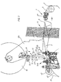
- the device 1 according to the invention is provided on the outlet side, which is arranged in the vicinity of the drawing-in roller 2 of the weaving machine and over which the fabric 3 runs (cf. FIG. 1).
- Shafts 6 are available.
- the compartment 4 is thus formed as a front compartment, while the rear compartment 7 is formed beyond the shafts.
- a deflecting shaft 13 is also fixedly arranged on the superstructure bracket 25 and serves to deflect the effect or pile warp threads 14 which are pulled off the pile warp beam 15.
- the pivot arm 12 is pivotally mounted, its pivot point 16 being adjustable in the arrow directions 17. This makes it possible to influence the rear compartment 7 in the altitude.
- the sensor shaft 11 has the task of acting simultaneously as a coating roller and as a dancer roller. It is important here that the effect or pile warp yarn sheet 14 is not divided by the arm 12 itself, because the sheet is deflected beyond the arm 12 via the sensing shaft 11.
- the pile warp beam 15 is motor-driven by a drive (not shown in more detail) via a motor that is precisely regulated in terms of speed and torque in order to ensure a low-tension withdrawal of the effect or pile warp threads 14.
- the swivel arm 12 is acted upon in the arrow direction 18 by a spring arrangement (not shown in more detail), so that it receives a certain pretension in the arrow direction 18 in order to load the effect or pile warp thread family 14 with a pretension, which, however, is very slight.
- the sensing shaft 11 thus pivots in the arrow directions 18, 19 shown about the pivot point 16.
- the swivel arm 12 serves as a sensing arm. That is to say, at position 20, a machine-specific proximity switch is arranged, to which a corresponding actuating element 21 on the sensing arm 12 is assigned.
- the distance 22 between these two elements is closely monitored by control electronics. This distance 22 is used as a control variable for controlling the speed of rotation for driving the pile chain beam 15. This ensures that the set of effect or pile warp threads 14 is always pulled off the pile warp beam 15 with a constant tension.
- the swivel arm 12 is designed with as little mass as possible in order to ensure a quick reaction.
- the sensing shaft 11 is formed from a thin-walled, hollow material;
- the swivel arm 12 is dimensioned as small as possible and made from a light metal material, for example aluminum or the like.
- the pivot bearing in the pivot point 16 is designed as smoothly as possible, e.g. designed as a ball bearing.
- the pivot arms 12 are on a common shaft, i.e. thus mounted on a common pivot point 16 which - as stated above - is vertically adjustable in the arrow directions 17.
- the fabric 3 is allowed to oscillate beyond the binding point 5 in order to achieve the desired high length addition in the case of effect or pile warp threads in comparison to the basic warp threads.
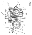
- the device consists in particular of a shaft 44 on which two eccentric disks 45 are arranged in a rotationally fixed manner at a mutual distance.
- the shaft is supported on the vertical side walls of the weaving machine housing 46. This shaft together with the shaft 36 extend over the entire width of the loom.
- FIG. 2 only one right-hand eccentric disk 45 is shown, while on the opposite side of the machine 46 a similar, identical eccentric disc is arranged.
- a roller lever 27 is pivotally mounted in a pivot bearing 28, a roller 29 running on the eccentric 45.
- the roller 29 is pressed against the eccentric disk 45 via a coupling 30, the coupling 30 consisting in particular of two joint rod heads 31 and 32, the joint rod head 31 engaging in an elongated hole 33 and being continuously displaceable there.
- the other joint rod head 32 is pivotally articulated on a clamp holder 34, which clamp holder 34 is pivotably mounted in a pivot bearing 35 on the bearing plate 26.
- the clamp holder 34 clamps a shaft 36, the clamp holder being shown in two different pivot positions.
- a pivot position is designated with position 34 '.
- the function of the device is as follows:
- the fabric 3 comes into the device 1 as a dashed line 37 (FIG. 2) and is deflected downward via the shaft 36.
- the shaft 36 is driven oscillating in the arrow directions 38 around the pivot bearing 35.
- the drive takes place via the eccentric disc 45, which rests non-positively on the roller 29.
- the roller 29 is deflected around the pivot bearing 28 and, via the infinitely adjustable coupling 30, the clamp holder 34 is pivotally driven in the arrow directions 38 around the bearing 35. So there is an oscillating movement, the frequency of which depends on the speed of the eccentric discs 45.
- One rotation of the eccentric discs 45 takes place per shot, so that an oscillating movement per Shot takes place.
- the entire tissue 3 is informed of an oscillating movement in the arrow directions 40, 41.
- This ensures that the effect or pile warp sheet 14 and the base warp sheet 24 are carried forward in the direction of arrow 41, but when moving back in the direction of arrow 40, the smoothly pivoting arm 12 ensures that the effect or pile warp sheet 14 remains, while the base warp sheet 24, which is under higher tension, due to its spring load, is relieved and thus decreases.
- the spring loading is achieved in a manner known per se by the basic match tree 42, which is spring-loaded and thus tensions the basic warp thread family in the direction of arrow 40.
- the base warp yarn sheet 24 will move backwards (also in the arrow direction 40) and take a larger path, while the pile warp yarn sheet 14 is not moved in the arrow direction 40 but remains there.
- the size of the desired length allowance can be set on the coupling 30.
- a length allowance could thus be set within relatively wide limits because this only depends on the setting of this device 1. Experiments by the applicant have shown that length addition of more than 41% is easy to achieve. The maximum upper limit is limited by the fabric properties.
Landscapes
- Engineering & Computer Science (AREA)
- Textile Engineering (AREA)
- Looms (AREA)
- Woven Fabrics (AREA)
Claims (6)
- Dispositif pour fabriquer un tissu à surface rugueuse sur des métiers à tisser, le tissu achevé, comprenant des fils de chaîne de fond, des fils de fantaisie ou des fils de chaîne de poil et des fils de trame, étant animé d'un mouvement alternatif oscillatoire se superposant, au point de liage, au mouvement normal d'enlèvement du tissu, au rythme 1:1 comme pour l'armure toile caractériqtique de tissus à surfaces rugueuses, de telle sorte que les fils de fantaisie ou de chaîne de poil subissent une augmentation de longueur comparativement aux fils de chaîne de fond, avec un entraînement dérivé de l'entraînement principal du métier a tisser, dispositif caractérisé par le fait que, côté sortie du métier à tisser et après le point de liage du tissu, un premier arbre (44) dépassant de la largeur du métier à tisser est supporté à mouvement rotatoire, par ses extrémités libres, par un palier (43) logé dans la paroi (46) du carter du métier à tisser ; par le fait qu'un disque (45) à excentrique est relié à l'arbre (44) à proximité du palier (43) considéré ; par le fait que chaque disque à excentrique est en liaison interactive avec un galet palpeur (29) d'un levier (27) à galet, agencé à mouvement rotatoire sur une plaque de portée (26) par le fait que chaque levier (27) à galet est relié, par l'intermédiaire d'une biellette (30), à un support de coincement (34) monté de manière oscillante ; par le fait que les supports de coincement (34) reçoivent les extrémités libres d'un second arbre (36) dépassant de la largeur du métier à tisser ; et par le fait que chaque support de coincement (34) est reçu par un palier de pivotement (35) agencé excentriquement par rapport à l'axe longitudinal de l'arbre (36).
- Dispositif selon la revendication 1, caractérisé par le fait que l'entraînement dérivé de l'entraînement principal est en liaison interactive avec le premier arbre (44).
- Dispositif selon la revendication 2, caractérisé par le fait que les disques (45) à excentriques du second arbre (36) impriment, à ce dernier, un mouvement alternatif pour chaque duite du métier à tisser.
- Dispositif selon la revendication 1, caractérisé par le fait que le levier (27) à galet présente un trou oblong (33) décrivant une courbe, dans lequel s'engage une tête d'articulation (31) reliant la biellette (30) au levier (27) à galet.
- Dispositif selon la revendication 4, caractérisé par le fait que la biellette (30) est réglable en continu ou par paliers, par l'intermédiaire de la tête d'articulation (31) s'engageant dans le trou oblong (33).
- Dispositif selon la revendication 5, caractérisé par le fait que des crans et des repères gradués (39) sont prévus, latéralement, sur la longueur du trou oblong (33).
Applications Claiming Priority (2)
| Application Number | Priority Date | Filing Date | Title |
|---|---|---|---|
| DE4005751A DE4005751A1 (de) | 1990-02-23 | 1990-02-23 | Seersucker-einrichtung |
| DE4005751 | 1990-02-23 |
Publications (2)
| Publication Number | Publication Date |
|---|---|
| EP0443343A1 EP0443343A1 (fr) | 1991-08-28 |
| EP0443343B1 true EP0443343B1 (fr) | 1994-06-15 |
Family
ID=6400827
Family Applications (1)
| Application Number | Title | Priority Date | Filing Date |
|---|---|---|---|
| EP91101038A Expired - Lifetime EP0443343B1 (fr) | 1990-02-23 | 1991-01-28 | Dispositif pour tisser un tissu à surface rugueuse |
Country Status (4)
| Country | Link |
|---|---|
| US (1) | US5099890A (fr) |
| EP (1) | EP0443343B1 (fr) |
| JP (1) | JPH05214636A (fr) |
| DE (2) | DE4005751A1 (fr) |
Families Citing this family (9)
| Publication number | Priority date | Publication date | Assignee | Title |
|---|---|---|---|---|
| DE4310840C1 (de) * | 1993-04-02 | 1994-01-13 | Dornier Gmbh Lindauer | Verfahren und Vorrichtung zur Beeinflussung der Zugspannung in einer Polkettfadenschar beim Herstellen von Frottiergewebe auf Webmaschinen |
| DE19530222C1 (de) * | 1995-08-17 | 1996-06-05 | Dornier Gmbh Lindauer | Steuersystem für die Polkette zur Herstellung von Frottiergewebe auf Webmaschinen |
| DE19530333C2 (de) * | 1995-08-17 | 1997-08-28 | Univ Eberhard Karls | Amplifikation von Pilzzellen-DNA sowie Verfahren zum Nachweisen von Pilzzellen in klinischem Material |
| DE10023445A1 (de) | 2000-05-12 | 2001-11-29 | Dornier Gmbh Lindauer | Frottierwebmaschine |
| DE10023444A1 (de) * | 2000-05-12 | 2001-11-29 | Dornier Gmbh Lindauer | Frottierwebmaschine |
| DE10054851A1 (de) | 2000-05-12 | 2002-05-29 | Dornier Gmbh Lindauer | Frottierwebmaschine |
| DE102005028127A1 (de) * | 2005-06-10 | 2006-12-14 | Picanol N.V. | Frottierwebmaschine |
| EP2180092B1 (fr) * | 2008-10-24 | 2012-11-21 | Groz-Beckert KG | Tendeur de largeur doté d'un dispositif de serrage et d'ouvrir |
| DE102011009765B3 (de) * | 2011-01-28 | 2011-11-10 | Lindauer Dornier Gmbh | Webmaschine mit verfahrbaren Begrenzungsmitteln sowie ein Verfahren zum Herstellen eines Gewebes |
Family Cites Families (9)
| Publication number | Priority date | Publication date | Assignee | Title |
|---|---|---|---|---|
| DD58072A (fr) * | ||||
| CH552693A (de) * | 1972-05-23 | 1974-08-15 | Sulzer Ag | Webmaschine zur herstellung von frottiergewebe. |
| CH564621A5 (fr) * | 1973-04-06 | 1975-07-31 | Sulzer Ag | |
| CH609386A5 (fr) * | 1976-01-20 | 1979-02-28 | Rueti Ag Maschf | |
| DE2817185B2 (de) * | 1978-04-20 | 1980-07-17 | Lindauer Dornier Gesellschaft Mbh, 8990 Lindau | Polkettfadenabwickelvorrichtung für eine Frottierwebmaschine |
| CH646472A5 (de) * | 1980-08-26 | 1984-11-30 | Saurer Ag Adolph | Einrichtung zum spannen der kettfadenscharen einer webmaschine. |
| EP0083905B2 (fr) * | 1982-01-13 | 1990-10-31 | GebràDer Sulzer Aktiengesellschaft | Métier pour tissu éponge comportant un élargisseur s'étendant dans la direction trame entre le pergne et la poitrinière |
| US4721134A (en) * | 1986-08-04 | 1988-01-26 | West Point Pepperell, Inc. | Terry loop ratio control device |
| JPH0718071B2 (ja) * | 1988-07-27 | 1995-03-01 | 津田駒工業株式会社 | サッカー織機 |
-
1990
- 1990-02-23 DE DE4005751A patent/DE4005751A1/de not_active Withdrawn
-
1991
- 1991-01-28 DE DE59101903T patent/DE59101903D1/de not_active Expired - Fee Related
- 1991-01-28 EP EP91101038A patent/EP0443343B1/fr not_active Expired - Lifetime
- 1991-02-22 JP JP3050338A patent/JPH05214636A/ja active Pending
- 1991-02-25 US US07/661,051 patent/US5099890A/en not_active Expired - Fee Related
Also Published As
| Publication number | Publication date |
|---|---|
| US5099890A (en) | 1992-03-31 |
| JPH05214636A (ja) | 1993-08-24 |
| DE59101903D1 (de) | 1994-07-21 |
| EP0443343A1 (fr) | 1991-08-28 |
| DE4005751A1 (de) | 1991-08-29 |
Similar Documents
| Publication | Publication Date | Title |
|---|---|---|
| DE69713348T2 (de) | Kettfadenkontrollvorrichtung zur herstellung von drehgewebe auf webmaschinen | |
| EP2126173B1 (fr) | Porte-fils de métier mécanique | |
| DE10128538B4 (de) | Webmaschine zum Herstellen eines Drehergewebes | |
| EP0443343B1 (fr) | Dispositif pour tisser un tissu à surface rugueuse | |
| EP0902109A1 (fr) | Dispositif de fournissage et de pinçage de fil de trame contrÔlable et ensemble de dispositifs pour la minimalisation des déchets de fil de trame pour le tissage sur métiers à tisser, plus particulièrement métiers à tisser à griffes | |
| EP0333930B1 (fr) | Métier à jet d'air | |
| EP0450120A1 (fr) | Procédé et dispositif de gaze pour la réalisation des fausses lisières d'un tissu double sur métier à doubles grittes | |
| DE20210613U1 (de) | Vorrichtung zum Nadeln eines Vlieses | |
| EP1299586B1 (fr) | Dispositif pour former un tissu de gaze | |
| DE2541990B2 (de) | Übernahmegreifer fur Webmaschinen | |
| EP0083905A1 (fr) | Métier pour tissu éponge comportant un élargisseur s'étendant dans la direction trame entre le pergne et la poitrinière | |
| EP3257983A1 (fr) | Métier à aiguilles pour tisser les rubans et procédé de tissage correspondant | |
| DE102008035434B4 (de) | Stoffdrücker einer Stickmaschine | |
| DE4132696C2 (de) | Breithalter und dessen Verwendung bei einer Webmaschine | |
| DE2333858C3 (de) | Vorrichtung zum Bewegen einer Wirknadel einer schützenlosen Webmaschine | |
| CH623869A5 (en) | Method for the guidance of weft threads, especially in jet-weaving machines, and device for carrying out this method. | |
| CH671784A5 (fr) | ||
| EP0358748B1 (fr) | Guide-etoffe | |
| DE9413705U1 (de) | Schaftvorrichtung | |
| DE2901497A1 (de) | Aufwickelvorrichtung zum direkten ziehen von glasfaser aus einer duesenplatte zur herstellung einer praezisionswicklung | |
| CH559793A5 (en) | Warp yarn let-off motion control - has a control unit for drive motor acting on positioning of the back rest | |
| DE19703002A1 (de) | Vorrichtung zum Schären einer Fadenschar auf einem Kettbaum | |
| WO2020025411A1 (fr) | Dispositif destiné à régler la tension de chaîne de fils de chaîne | |
| WO2025237686A1 (fr) | Appareil de régulation de tension de bord de tissu, machine à tisser comprenant un tel appareil et procédé de régulation de tension de bord de tissu | |
| EP0187181B1 (fr) | Métier à tisser |
Legal Events
| Date | Code | Title | Description |
|---|---|---|---|
| PUAI | Public reference made under article 153(3) epc to a published international application that has entered the european phase |
Free format text: ORIGINAL CODE: 0009012 |
|
| AK | Designated contracting states |
Kind code of ref document: A1 Designated state(s): BE CH DE FR GB IT LI |
|
| 17P | Request for examination filed |
Effective date: 19911216 |
|
| 17Q | First examination report despatched |
Effective date: 19931206 |
|
| GRAA | (expected) grant |
Free format text: ORIGINAL CODE: 0009210 |
|
| AK | Designated contracting states |
Kind code of ref document: B1 Designated state(s): BE CH DE FR GB IT LI |
|
| REF | Corresponds to: |
Ref document number: 59101903 Country of ref document: DE Date of ref document: 19940721 |
|
| ITF | It: translation for a ep patent filed | ||
| GBT | Gb: translation of ep patent filed (gb section 77(6)(a)/1977) |
Effective date: 19940818 |
|
| ET | Fr: translation filed | ||
| PLBE | No opposition filed within time limit |
Free format text: ORIGINAL CODE: 0009261 |
|
| STAA | Information on the status of an ep patent application or granted ep patent |
Free format text: STATUS: NO OPPOSITION FILED WITHIN TIME LIMIT |
|
| 26N | No opposition filed | ||
| PGFP | Annual fee paid to national office [announced via postgrant information from national office to epo] |
Ref country code: DE Payment date: 19960116 Year of fee payment: 6 |
|
| PGFP | Annual fee paid to national office [announced via postgrant information from national office to epo] |
Ref country code: GB Payment date: 19961217 Year of fee payment: 7 |
|
| PGFP | Annual fee paid to national office [announced via postgrant information from national office to epo] |
Ref country code: CH Payment date: 19961218 Year of fee payment: 7 |
|
| PGFP | Annual fee paid to national office [announced via postgrant information from national office to epo] |
Ref country code: FR Payment date: 19961227 Year of fee payment: 7 |
|
| PGFP | Annual fee paid to national office [announced via postgrant information from national office to epo] |
Ref country code: BE Payment date: 19970106 Year of fee payment: 7 |
|
| PG25 | Lapsed in a contracting state [announced via postgrant information from national office to epo] |
Ref country code: DE Effective date: 19971001 |
|
| PG25 | Lapsed in a contracting state [announced via postgrant information from national office to epo] |
Ref country code: GB Free format text: LAPSE BECAUSE OF NON-PAYMENT OF DUE FEES Effective date: 19980128 |
|
| PG25 | Lapsed in a contracting state [announced via postgrant information from national office to epo] |
Ref country code: LI Free format text: LAPSE BECAUSE OF NON-PAYMENT OF DUE FEES Effective date: 19980131 Ref country code: FR Free format text: THE PATENT HAS BEEN ANNULLED BY A DECISION OF A NATIONAL AUTHORITY Effective date: 19980131 Ref country code: CH Free format text: LAPSE BECAUSE OF NON-PAYMENT OF DUE FEES Effective date: 19980131 Ref country code: BE Free format text: LAPSE BECAUSE OF NON-PAYMENT OF DUE FEES Effective date: 19980131 |
|
| BERE | Be: lapsed |
Owner name: LINDAUER DORNIER G.M.B.H. Effective date: 19980131 |
|
| REG | Reference to a national code |
Ref country code: CH Ref legal event code: PL |
|
| GBPC | Gb: european patent ceased through non-payment of renewal fee |
Effective date: 19980128 |
|
| REG | Reference to a national code |
Ref country code: FR Ref legal event code: ST |
|
| PG25 | Lapsed in a contracting state [announced via postgrant information from national office to epo] |
Ref country code: IT Free format text: LAPSE BECAUSE OF NON-PAYMENT OF DUE FEES;WARNING: LAPSES OF ITALIAN PATENTS WITH EFFECTIVE DATE BEFORE 2007 MAY HAVE OCCURRED AT ANY TIME BEFORE 2007. THE CORRECT EFFECTIVE DATE MAY BE DIFFERENT FROM THE ONE RECORDED. Effective date: 20050128 |