EP0443418B1 - Machine textile - Google Patents
Machine textile Download PDFInfo
- Publication number
- EP0443418B1 EP0443418B1 EP91101966A EP91101966A EP0443418B1 EP 0443418 B1 EP0443418 B1 EP 0443418B1 EP 91101966 A EP91101966 A EP 91101966A EP 91101966 A EP91101966 A EP 91101966A EP 0443418 B1 EP0443418 B1 EP 0443418B1
- Authority
- EP
- European Patent Office
- Prior art keywords
- textile
- control unit
- belt
- drive
- machine according
- Prior art date
- Legal status (The legal status is an assumption and is not a legal conclusion. Google has not performed a legal analysis and makes no representation as to the accuracy of the status listed.)
- Expired - Lifetime
Links
Images

Classifications
-
- D—TEXTILES; PAPER
- D01—NATURAL OR MAN-MADE THREADS OR FIBRES; SPINNING
- D01H—SPINNING OR TWISTING
- D01H9/00—Arrangements for replacing or removing bobbins, cores, receptacles, or completed packages at paying-out or take-up stations ; Combination of spinning-winding machine
- D01H9/18—Arrangements for replacing or removing bobbins, cores, receptacles, or completed packages at paying-out or take-up stations ; Combination of spinning-winding machine for supplying bobbins, cores, receptacles, or completed packages to, or transporting from, paying-out or take-up stations ; Arrangements to prevent unwinding of roving from roving bobbins
-
- B—PERFORMING OPERATIONS; TRANSPORTING
- B65—CONVEYING; PACKING; STORING; HANDLING THIN OR FILAMENTARY MATERIAL
- B65H—HANDLING THIN OR FILAMENTARY MATERIAL, e.g. SHEETS, WEBS, CABLES
- B65H67/00—Replacing or removing cores, receptacles, or completed packages at paying-out, winding, or depositing stations
- B65H67/04—Arrangements for removing completed take-up packages and or replacing by cores, formers, or empty receptacles at winding or depositing stations; Transferring material between adjacent full and empty take-up elements
- B65H67/0428—Arrangements for removing completed take-up packages and or replacing by cores, formers, or empty receptacles at winding or depositing stations; Transferring material between adjacent full and empty take-up elements for cans, boxes and other receptacles
-
- D—TEXTILES; PAPER
- D01—NATURAL OR MAN-MADE THREADS OR FIBRES; SPINNING
- D01G—PRELIMINARY TREATMENT OF FIBRES, e.g. FOR SPINNING
- D01G21/00—Combinations of machines, apparatus, or processes, e.g. for continuous processing
-
- D—TEXTILES; PAPER
- D01—NATURAL OR MAN-MADE THREADS OR FIBRES; SPINNING
- D01H—SPINNING OR TWISTING
- D01H5/00—Drafting machines or arrangements ; Threading of roving into drafting machine
-
- B—PERFORMING OPERATIONS; TRANSPORTING
- B65—CONVEYING; PACKING; STORING; HANDLING THIN OR FILAMENTARY MATERIAL
- B65H—HANDLING THIN OR FILAMENTARY MATERIAL, e.g. SHEETS, WEBS, CABLES
- B65H2701/00—Handled material; Storage means
- B65H2701/30—Handled filamentary material
- B65H2701/31—Textiles threads or artificial strands of filaments
Definitions
- the invention relates to a textile machine according to the preamble of claim 1.
- the feed and discharge unit seen in terms of control and drive, are fully integrated into the drive and control unit of the textile processing machine.
- Today's drive technology especially the single drive via electric motors, enables a very finely tuned and controllable drive, whereby the communication of individual drive groups can also be carried out easily and with almost no losses.
- a textile processing machine which delivers the textile material, in this case a sliver, to a can filling station provided with its own drive. Differences in the delivery speed of the sliver between the textile processing machine and the subsequent can filling station are detected by a sensor device and the drive of the can filling station is regulated according to the values determined in the process.
- the central filling computer and the textile processing machine are controlled by a central control computer.
- this system is not readily transferable to the supply of textile material by means of a supply device to the textile processing machine.
- a supply device to the textile processing machine.
- a feed unit can also be started independently of the subsequent textile processing machine. This is particularly necessary when a new batch of textile material has to be set up and positioned accordingly for transfer to the textile processing machine. This is particularly the case if a part of the discarded textile material is kept on hold as a reserve material.
- FR-A 25 87 042 proposes that the position of "Flexafeed" flaps on a card be recorded by a central control unit in order to determine the new routes and destinations of a transport trolley depending on the flap position.
- the dispensing unit on the card has no control of its own, so that a material jam on the textile machine cannot be avoided.
- DE-OS 32 37 864 describes the closest prior art to a textile machine for processing textile material with a control and drive unit and a feed device for feeding textile material which is removed from the textile material store associated with the feed device.
- the textile processing machine is also assigned a tape storage device, which delivers the textile material to the corresponding storage device.
- DE-OS 32 37 864 also shows that the feed device is equipped with an independent control and drive unit. This also applies to the tape storage.
- This solution is disadvantageous, as shown below. If a transport system takes over filled cans from the textile machine on the conveyor, the operation of the feed device continues without a can change being taken into account. This can lead to belt jams or undesired belt warping in the textile machine. This malfunction caused by the feeding device must be avoided.
- This solution also presents difficulties when connecting an end of the tape that is running out to a new tape to be introduced. There is a risk of incorrect positioning of the tape end, since the feed device runs at a lower speed when the reserve tape is switched on in the start-up phase and the processing speed of the dispensing device cannot be controlled to the state of the reserve tape feed.
- the invention is based on the object of designing the individual drive and control concepts of both a feed device and a belt storage of a textile-processing machine in such a way that interaction with transport systems for sliver material is possible from the point of view of automation.
- Automation can be understood on the one hand to mean the automatic tracking of textile material without stopping the textile processing machine and on the other hand the connection to an automatic transport system for the textile material.
- the solution according to the invention has the advantage that the feed speed can be controlled in synchronization with the processing speed.
- Another advantage results from the possibility that a failure of a thread band can be reported to the control computer of the transport system in the feed device. It is thus achieved that a connection of an outgoing sliver to the start of a switched-on reserve sliver is possible by exact sliver end positioning.
- each conveyor belt of a feed device has its own drive motor which is guided by the control unit of the feed device. This enables a targeted and separate reserve band connection.
- the conveyor belts for the work belt and reserve belt are preferably combined in pairs.
- the conveyor belts each have a withdrawal device for withdrawing the sliver from a can.
- an attenuator was connected in the connection path between the corresponding control and regulating devices.
- stepper motors results in an exact determination of the position during the entire transport process of the sliver, e.g. a beginning of a sliver, seen in the direction of transport.
- electronically commutated brushless motors e.g. DC motors have the advantage that the drive of the conveyor belt can also work in the overload range at short notice and without problems.
- the teaching claimed by the invention provides a good possibility of regulating the entire system through direct control.
- the independent drive also shortens the drive distances and thus also reduces losses.
- the drives can be designed specifically for the individual purpose.
- the proposed control, regulation and drive-related separation enables better allocation and communication to an assigned automatic transport system for the textile material.
- Figure 1 shows a textile processing machine, e.g. a route 1, which is provided with a drafting system, not shown.
- a feed table 2 is provided as the feed unit, and a belt storage 3 is provided as the delivery unit.
- Cans A, R for removing fiber slivers are set up along the feed table 2.
- the space which the cans A, R occupy is generally also referred to as a can rack 4.
- empty spaces can also be provided for receiving cans by the transport unit. This can improve the logistics of the transport system and thus its effectiveness.
- the directional arrow P shows the feed and the direction of passage of the textile material before it reaches the tape storage 3.
- a transport system T 1 with a driverless transport vehicle 5 guided over a guideline 6 is assigned to the feed table 2 or the can frame 4.
- the transport vehicle 5 is controlled by a control computer 7. This means that the transport vehicle receives the drive command or the drive order from the control computer 7 via a connection 8.
- the connection 8 can be wireless, via a connection cable or via a communication station.
- the drive 9 of the feed table 2 and the sensor system 10 is shown schematically.
- the drive 9 is connected to a control unit 13 via a path 11 and the sensor system 10 via a path 12.
- the control unit 13 communicates via the line 14 with the control computer 7 of the transport system T 1 .
- the paths 15 and 16 form a communication option between the control unit 17 of the drive unit 18 of the route 1.
- the schematically illustrated sensor system 19 of the route 1 is connected to the control unit 17 via the path 21.
- the two connections 22 and 23 enable communication between the control unit 17 and the control unit 24 of the tape storage unit 3.
- the control unit 24 is connected via the paths 25 to a schematically illustrated drive 26 and via the path 27 to a sensor system 28 of the tape storage unit 3.
- the control computer 30 communicates via a connection 32 with a transport vehicle 31, which is guided via a guide 33.
- a can F 2 is in the filling station, while an empty can F 1 is ready for tracking.
- F3 denotes a filled can, which was ejected from the tape storage 3 after the filling process and is ready for reception by the transport vehicle 31.
- the guideline 33 is provided with a reversing loop 34.
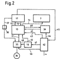
- FIG. 2 shows a more detailed breakdown of the drive and control mechanism for the feed table 2.
- a motor electronics 35 which acts on a motor 36.
- a connection 37 into which an attenuator 38 is switched on.
- the motor electronics 35 or the motor 36 receives a command signal via this connection 37 in order to ensure the synchronization with respect to the feed speed of the textile material and the processing speed.
- the motor electronics are controlled via the path 11 by the control unit 13.
- the lines 40 and 41 represent a connection between the control unit 13 and a display and operating unit 39.
- a voltage supply unit 42 supplies the display and operating unit via line 44, the control unit 13 via line 43, and the sensor system via line 47 10 and via line 46 the motor electronics 35 with current.
- the power supply 42 is switched on by the control unit 17 of the line 1 via the line 45. In the specific case, this means that the voltage supply 42 only becomes effective when the control unit 17 or. route 1 is switched on.
- the connection 48 between the sensor system 10 and the motor electronics 35 makes it possible to intervene directly in the motor electronics for motor control. In certain cases, this allows the reaction time to change the engine speed to be shortened, since the computer unit of the control unit 13 is bypassed.
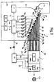
- FIG. 3 An exemplary embodiment is shown in FIG. 3, the feed table 2 being composed of a total of eight individual conveyor belts B 1 to B 8 .
- Each conveyor belt B 1 to B 8 is equipped with a separate drive motor 36 1 to 36 8 .
- the drive motors 36 1 to 36 8 are each located above a draw-off point above a can, only one can A being shown because of the better overview.
- the other seven cans are assigned accordingly.
- swiveling pressure rollers 49 are assigned to each of the withdrawal points. During operation, these rollers 49 move in the direction of the respective conveyor belt B 1 to B 8 and thereby enable the respective sliver to be pulled off by the clamping between the conveyor belt and the pressure roller 49.
- sliver 50 at the transfer point 52 submitted the route 1.
- the slivers 50 released in the process are combined at this transfer point 52 (not shown) to form a sliver fleece before it is fed to the drafting system of the section 1.
- the other slivers also called reserve belts 51 in this operating state, are in the starting position below a sensor row S and are switched on in accordance with the failure of a sliver 50, i.e. one of the conveyor belts B 1 to B 8 must be started up and switched on via the respective motor 36 .
- the monitoring of the slivers or the sliver break can also take place directly in the area of the withdrawal points.
- the transport vehicle 5 with the guideline 6 is only indicated schematically here.
- the line 1 and the tape storage 3 are connected to form a unit, which are controlled by a control unit 17.
- the sensor system 19 of the route 1 and the sensor system 28 of the tape storage 3 are connected to the control unit 17 via the paths 21 and 27.
- the special indication of the respective drive unit has been omitted.
- a control signal is transmitted from route 1 via control unit 17 and control unit 13 to the individual electronic control units 35 1 to 35 8 of motors 36 1 to 36 8 .
- An attenuator 38 is installed in the path 16 provided for this purpose to damp short-wave signals.
- Each can parking space is assigned a can sensor 53, which is connected to the control unit 13 via a line 54 and the sensor system 10 and the path 12. For reasons of clarity, only one sensor 53 was shown in the example in FIG. 3.
- the sensors 53 can also on the one hand to check whether a jug is present, or on the other hand to check the contents of the jug. These signals received by the sensors 53 are relevant for the provision of cans and for the preparation of the tracking of a reserve belt.
- the further insertion of the fiber slivers 50 into the subsequent drafting device or the fiber sliver that subsequently emerges from the drafting device into the sliver storage can be done manually or automatically.
- the engine speed of the motors 36 1 to 36 8 is adjusted according to the control dynamics of the drafting system of the route 1 via the path 16.
- a sliver breaks down as a result of a sliver break or an empty can, after notification via the sensor system 10, the corresponding conveyor belt B is switched on with the reserve belt 51, in such a way that the end of the sliver running out coincides with the start of the connected reserve belt 51 covered. This requires an exact sensor system and an exact start of the corresponding conveyor belt.
- the report of a failed sliver or an empty can is transmitted by the control unit 13 via the line 14 to the control computer 7 of the transport system T 1 . With this transmission, the position of the stand of the empty can is also transmitted, whereby the host computer can transmit a clear driving order to the transport vehicle 5 for picking up and replacing the corresponding can with a new filled can.
- a further transport system T 2 was not shown in FIG. 3. However, the structure could be similar to that shown in the example in FIG. 1.
- the example according to FIG. 1 differs essentially from that in FIG. 3 in that the section 1 and the tape storage 3 each have their own control and drive unit, which communicate with one another via the respective control unit 17 or 24. Otherwise, the example according to FIG. 1 differs insignificantly from the example according to FIG. 3.
- FIG. 3 only the feed table 2 was shown in a special embodiment and with a finer structure.
- the additional transport system T 2 in the example of FIG. 1 has the task of conveying empty cans F 1 to the band deposit and to transport away the full cans F3 ejected in this band deposit 3.
- the control unit 30 of this transport system T 2 is connected to the control unit 24 of the tape storage 3 via the path 29.
Landscapes
- Engineering & Computer Science (AREA)
- Textile Engineering (AREA)
- Mechanical Engineering (AREA)
- Spinning Or Twisting Of Yarns (AREA)
Claims (7)
- Machine textile pour la transformation de matière textile, comprenant une installation d'amenée (2), servant à l'amenée de matière textile, ainsi qu'une station (3) pour le dépôt du ruban, monté en aval de la machine textile, et qui transmet la matière textile fournie à des accumulateurs (F2) correspondant et est équipé d'unités de commande séparées (13, 17, 24), caractérisée en ce que l'unité de commande (13, 24) de l'installation d'amenée (2) et/ou de la station (3) de dépôt du ruban est en liaison avec une unité de commande (30, 7) d'un système de transport automatique (T1 , T2).
- Machine textile selon la revendication 1, caractérisée en ce que l'installation d'amenée (2) est composée de plusieurs bandes transporteuses tournant (B1 - B8) qui transportent la matière textile vers la machine (1) transformant la matière textile sous forme de rubans de fibres (50, 51).
- Machine textile selon la revendication 2, caractérisée en ce qu'à chaque bande transporteuse (B1 - B8) il est attribué un moteur de commande (361 - 368) qui est relié à une unité de commande électronique (351 - 358) et en ce que l'unité de commande électronique respective (351 - 358) est reliée à l'unité de commande (13).
- Machine textile selon la revendication 2, caractérisée en ce que le nombre de bandes transporteuses (B1 - B8) est plus grand que le nombre de rubans de fibres (50, 51) a recueillir par la machine transformant la matière textile.
- Machine textile selon la revendication 4, caractérisée en ce que les bandes transporteuses (B1 - B8) sont groupées par deux, l'une constituant la bande de travail et l'autre la bande de réserve (B1, B2).
- Machine texile selon la revendication 2, caractérisée en ce que les bandes transporteuses (B1 - B8) sont pourvues d'une installation d'extraction (49) servant au retrait des rubans de fibres (50, 51) de l'accumulateur (A) de matière textile respectif attribué.
- Machine texile selon la revendication 2, caractérisée en ce que la voie (37) connectant l'unité (17) de commande et de régulation de la machine (1) transformant la matière textile et l'électronique de commande (35) des moteurs (36) de commande d'une installation d'amenée (2) est pourvue d'un atténuateur (38) servant à la filtration de signaux à ondes courtes.
Applications Claiming Priority (3)
| Application Number | Priority Date | Filing Date | Title |
|---|---|---|---|
| CH557/90A CH681632A5 (fr) | 1990-02-21 | 1990-02-21 | |
| CH55790 | 1990-02-21 | ||
| CH557/90 | 1990-02-21 |
Publications (3)
| Publication Number | Publication Date |
|---|---|
| EP0443418A1 EP0443418A1 (fr) | 1991-08-28 |
| EP0443418B1 true EP0443418B1 (fr) | 1996-10-23 |
| EP0443418B2 EP0443418B2 (fr) | 2001-11-21 |
Family
ID=4189767
Family Applications (1)
| Application Number | Title | Priority Date | Filing Date |
|---|---|---|---|
| EP91101966A Expired - Lifetime EP0443418B2 (fr) | 1990-02-21 | 1991-02-13 | Machine textile |
Country Status (6)
| Country | Link |
|---|---|
| US (1) | US5226212A (fr) |
| EP (1) | EP0443418B2 (fr) |
| JP (1) | JPH06316819A (fr) |
| CH (1) | CH681632A5 (fr) |
| CS (1) | CS38391A2 (fr) |
| DE (1) | DE59108289D1 (fr) |
Families Citing this family (3)
| Publication number | Priority date | Publication date | Assignee | Title |
|---|---|---|---|---|
| DE19719765A1 (de) | 1997-05-10 | 1998-11-12 | Rieter Ingolstadt Spinnerei | Verfahren und Vorrichtung zum Transportieren einer Kannengruppe |
| DE19809875B4 (de) * | 1998-03-07 | 2014-01-02 | Trützschler GmbH & Co Kommanditgesellschaft | Vorrichtung zum Zuführen von Faserbändern an Streckwerken von Spinnereimaschinen, insbesondere von Strecken |
| CN111910302B (zh) * | 2019-05-09 | 2024-07-02 | 北自所(北京)科技发展股份有限公司 | 预并至条并卷的条筒自动输送暂存系统及方法 |
Family Cites Families (17)
| Publication number | Priority date | Publication date | Assignee | Title |
|---|---|---|---|---|
| US3443287A (en) * | 1962-02-09 | 1969-05-13 | Schubert & Salzer Maschinen | Can changing in strand material handling |
| CH546286A (it) * | 1971-06-22 | 1974-02-28 | Montecchi Federico | Dispositivo per l'alimentazione automatica di nastri di fibre tessili raccolti in vasi a macchine operatrici quali pettinatrici, stiratoi, mescolatrici. |
| JPS5022626B2 (fr) * | 1972-10-19 | 1975-08-01 | ||
| US4179773A (en) * | 1978-04-27 | 1979-12-25 | Platt Saco Lowell Limited | Means for severing and compacting coiled sliver |
| DE3237864C2 (de) * | 1982-10-13 | 1996-05-23 | Truetzschler Gmbh & Co Kg | Verfahren und Vorrichtung zum Steuern und Regeln einer Spinnereivorbereitungsanlage |
| IN161184B (fr) * | 1983-06-21 | 1987-10-17 | Rieter Ag Maschf | |
| DE3324461C1 (de) * | 1983-07-07 | 1984-10-25 | Trützschler GmbH & Co KG, 4050 Mönchengladbach | Vorrichtung zum Trennen eines Faserbandes beim Kannenwechsel an Spinnereivorbereitungsmaschinen |
| US4735040A (en) * | 1985-04-30 | 1988-04-05 | Buro Patent Ag | Method of and apparatus for the automatic feeding of filled cans and the automatic removal of empty cans from the spinning units of a spinning machine |
| DE3532172A1 (de) * | 1985-09-10 | 1987-03-12 | Truetzschler & Co | Vorrichtung zum automatischen transport mindestens einer kanne zwischen einer faserbandabliefernden spinnereimaschine und einer faserbandgespeisten spinnereimaschine |
| DE3733632C2 (de) * | 1987-10-05 | 1998-04-23 | Truetzschler Gmbh & Co Kg | Vorrichtung bei einer Karde oder Krempel zur Vergleichmäßigung des Faserbandes oder -vlieses |
| US4807430A (en) * | 1987-10-22 | 1989-02-28 | Walker Magnetics Group, Inc. | Thread wrapping apparatus |
| DE3821238A1 (de) * | 1988-06-23 | 1989-12-28 | Rieter Ag Maschf | Verfahren und vorrichtung zur herstellung eines gleichmaessigen faserbandes |
| IL90789A0 (en) * | 1988-08-05 | 1990-01-18 | Rieter Ag Maschf | Textile machine with drawframes |
| PT91966B (pt) * | 1988-11-03 | 1995-08-09 | Rieter Ag Maschf | Mesa de entrada dupla |
| PT91964B (pt) * | 1988-11-03 | 1995-09-12 | Rieter Ag Maschf | Mesa de entrada de uma estiradeira |
| CH677782A5 (fr) * | 1988-11-28 | 1991-06-28 | Rieter Ag Maschf | |
| US5067202A (en) * | 1989-07-26 | 1991-11-26 | Maschinenfabrik Rieter Ag | Method of maintaining a predetermined quantity of sliver in a card and/or drawframe |
-
1990
- 1990-02-21 CH CH557/90A patent/CH681632A5/de not_active IP Right Cessation
-
1991
- 1991-02-12 US US07/655,294 patent/US5226212A/en not_active Expired - Lifetime
- 1991-02-13 DE DE59108289T patent/DE59108289D1/de not_active Expired - Fee Related
- 1991-02-13 EP EP91101966A patent/EP0443418B2/fr not_active Expired - Lifetime
- 1991-02-14 CS CS91383A patent/CS38391A2/cs unknown
- 1991-02-19 JP JP3024554A patent/JPH06316819A/ja active Pending
Also Published As
| Publication number | Publication date |
|---|---|
| EP0443418B2 (fr) | 2001-11-21 |
| JPH06316819A (ja) | 1994-11-15 |
| US5226212A (en) | 1993-07-13 |
| CS38391A2 (en) | 1991-09-15 |
| CH681632A5 (fr) | 1993-04-30 |
| EP0443418A1 (fr) | 1991-08-28 |
| DE59108289D1 (de) | 1996-11-28 |
Similar Documents
| Publication | Publication Date | Title |
|---|---|---|
| EP0296547B1 (fr) | Procédé et dispositif pour la jonction automatique d'un ruban de fibres discontinues | |
| DE3919542A1 (de) | Automatische spulmaschine mit einem kops- und huelsentransportsystem mit mehreren transportschleifen | |
| EP0272398A1 (fr) | Dispositif pour transférer des produits imprimés arrivant en une ligne vers la ligne d'alimentation d'une station de transformation | |
| DE2230644C3 (de) | Vorrichtung zum automatischen Zuführen von Textilfaserbändern aus Behältern zu Verarbeitungsmaschinen | |
| DE102012016482A1 (de) | Spinnkops- und Hülsentransportsystem für eine Kreuzspulen herstellende Textilmaschine | |
| EP1006069B1 (fr) | Bobinoir automatique à fil croisé et procédé de fonctionnement d'un bobinoir automatique à fil croisé | |
| EP0443418B1 (fr) | Machine textile | |
| DE19905856B4 (de) | Hülsenliefereinrichtung für eine Kreuzspulen herstellende Textilmaschine | |
| EP0374431A2 (fr) | Bobinoir automatique avec bande transporteuse pour supports de bobines | |
| EP0344102A2 (fr) | Dispositif d'assemblage de produits imprimés | |
| DE102007038871B4 (de) | Verfahren zum Anspinnen an Textilmaschinen mit einer Mehrzahl von Spinnstellen | |
| EP0329602B1 (fr) | Procédé et dispositif pour emmagasiner et convertir des produits plats de préférence arrivant dans une formation en écailles | |
| DE3902978C2 (fr) | ||
| DE4211112C2 (de) | Vorrichtung zum Beliefern eines Spulautomaten mit aufrechtstehend auf Spulentransportteller aufgesteckten Kopsen | |
| EP0367042B1 (fr) | Table d'alimentation double | |
| DE102009050582A1 (de) | Verfahren zum Anspinnen einer Offenend-Rotorspinnvorrichtung | |
| DE4233819C2 (de) | Verfahren zum Betreiben einer automatischen Spulmaschine bei Partiewechsel | |
| EP0569772B1 (fr) | Procédé et dispositif pour la fabrication d'un nombre donné de bobines pleines croisées sur une machine de bobinage à spires croisées | |
| DE102018132459A1 (de) | Kreuzspulen herstellende Textilmaschine mit einer Kreuzspulentransporteinrichtung | |
| EP4021835B1 (fr) | Dispositif d'alimentation en tubes destiné à une machine textile qui produit des bobines croisées | |
| DE19749024B4 (de) | Spinnanlage mit Vorspinnmaschinen und mit Ringspinnmaschinen | |
| DE4210815C2 (de) | Zuführeinrichtung für aufrechtstehende auf Spulentransportteller aufgesteckte Kopse zu den Spulstellen einer Spulmaschine | |
| DE3622004C2 (fr) | ||
| EP0511158A1 (fr) | Procédé et dispositif pour le transfert de canettes et tubes de bobine entre un métier à filer à anneaux et une machine à bobiner associée | |
| EP1476594B1 (fr) | Machine a texturer |
Legal Events
| Date | Code | Title | Description |
|---|---|---|---|
| PUAI | Public reference made under article 153(3) epc to a published international application that has entered the european phase |
Free format text: ORIGINAL CODE: 0009012 |
|
| AK | Designated contracting states |
Kind code of ref document: A1 Designated state(s): CH DE FR GB IT LI |
|
| 17P | Request for examination filed |
Effective date: 19910917 |
|
| 17Q | First examination report despatched |
Effective date: 19940126 |
|
| GRAG | Despatch of communication of intention to grant |
Free format text: ORIGINAL CODE: EPIDOS AGRA |
|
| GRAH | Despatch of communication of intention to grant a patent |
Free format text: ORIGINAL CODE: EPIDOS IGRA |
|
| GRAH | Despatch of communication of intention to grant a patent |
Free format text: ORIGINAL CODE: EPIDOS IGRA |
|
| GRAA | (expected) grant |
Free format text: ORIGINAL CODE: 0009210 |
|
| AK | Designated contracting states |
Kind code of ref document: B1 Designated state(s): CH DE FR GB IT LI |
|
| PG25 | Lapsed in a contracting state [announced via postgrant information from national office to epo] |
Ref country code: GB Effective date: 19961023 |
|
| ET | Fr: translation filed | ||
| ITF | It: translation for a ep patent filed | ||
| REF | Corresponds to: |
Ref document number: 59108289 Country of ref document: DE Date of ref document: 19961128 |
|
| PGFP | Annual fee paid to national office [announced via postgrant information from national office to epo] |
Ref country code: FR Payment date: 19970114 Year of fee payment: 7 |
|
| PGFP | Annual fee paid to national office [announced via postgrant information from national office to epo] |
Ref country code: CH Payment date: 19970131 Year of fee payment: 7 |
|
| GBV | Gb: ep patent (uk) treated as always having been void in accordance with gb section 77(7)/1977 [no translation filed] |
Effective date: 19961023 |
|
| PLBQ | Unpublished change to opponent data |
Free format text: ORIGINAL CODE: EPIDOS OPPO |
|
| PLBI | Opposition filed |
Free format text: ORIGINAL CODE: 0009260 |
|
| 26 | Opposition filed |
Opponent name: TRUETZSCHLER GMBH & CO. KG Effective date: 19970616 |
|
| PLBF | Reply of patent proprietor to notice(s) of opposition |
Free format text: ORIGINAL CODE: EPIDOS OBSO |
|
| PLBQ | Unpublished change to opponent data |
Free format text: ORIGINAL CODE: EPIDOS OPPO |
|
| PLAB | Opposition data, opponent's data or that of the opponent's representative modified |
Free format text: ORIGINAL CODE: 0009299OPPO |
|
| R26 | Opposition filed (corrected) |
Opponent name: TRUETZSCHLER GMBH & CO. KG Effective date: 19970616 |
|
| PLBF | Reply of patent proprietor to notice(s) of opposition |
Free format text: ORIGINAL CODE: EPIDOS OBSO |
|
| PG25 | Lapsed in a contracting state [announced via postgrant information from national office to epo] |
Ref country code: LI Free format text: LAPSE BECAUSE OF NON-PAYMENT OF DUE FEES Effective date: 19980228 Ref country code: FR Free format text: THE PATENT HAS BEEN ANNULLED BY A DECISION OF A NATIONAL AUTHORITY Effective date: 19980228 Ref country code: CH Free format text: LAPSE BECAUSE OF NON-PAYMENT OF DUE FEES Effective date: 19980228 |
|
| REG | Reference to a national code |
Ref country code: CH Ref legal event code: PL |
|
| REG | Reference to a national code |
Ref country code: FR Ref legal event code: ST |
|
| PLBO | Opposition rejected |
Free format text: ORIGINAL CODE: EPIDOS REJO |
|
| APAC | Appeal dossier modified |
Free format text: ORIGINAL CODE: EPIDOS NOAPO |
|
| APAE | Appeal reference modified |
Free format text: ORIGINAL CODE: EPIDOS REFNO |
|
| APAC | Appeal dossier modified |
Free format text: ORIGINAL CODE: EPIDOS NOAPO |
|
| APAE | Appeal reference modified |
Free format text: ORIGINAL CODE: EPIDOS REFNO |
|
| APAC | Appeal dossier modified |
Free format text: ORIGINAL CODE: EPIDOS NOAPO |
|
| PLAW | Interlocutory decision in opposition |
Free format text: ORIGINAL CODE: EPIDOS IDOP |
|
| PUAH | Patent maintained in amended form |
Free format text: ORIGINAL CODE: 0009272 |
|
| STAA | Information on the status of an ep patent application or granted ep patent |
Free format text: STATUS: PATENT MAINTAINED AS AMENDED |
|
| 27A | Patent maintained in amended form |
Effective date: 20011121 |
|
| AK | Designated contracting states |
Kind code of ref document: B2 Designated state(s): CH DE FR GB IT LI |
|
| EN | Fr: translation not filed | ||
| PGFP | Annual fee paid to national office [announced via postgrant information from national office to epo] |
Ref country code: DE Payment date: 20040126 Year of fee payment: 14 |
|
| PG25 | Lapsed in a contracting state [announced via postgrant information from national office to epo] |
Ref country code: IT Free format text: LAPSE BECAUSE OF NON-PAYMENT OF DUE FEES;WARNING: LAPSES OF ITALIAN PATENTS WITH EFFECTIVE DATE BEFORE 2007 MAY HAVE OCCURRED AT ANY TIME BEFORE 2007. THE CORRECT EFFECTIVE DATE MAY BE DIFFERENT FROM THE ONE RECORDED. Effective date: 20050213 |
|
| PG25 | Lapsed in a contracting state [announced via postgrant information from national office to epo] |
Ref country code: DE Free format text: LAPSE BECAUSE OF NON-PAYMENT OF DUE FEES Effective date: 20050901 |
|
| APAH | Appeal reference modified |
Free format text: ORIGINAL CODE: EPIDOSCREFNO |