EP0443517B1 - Foret à embout jetable - Google Patents
Foret à embout jetable Download PDFInfo
- Publication number
- EP0443517B1 EP0443517B1 EP91102345A EP91102345A EP0443517B1 EP 0443517 B1 EP0443517 B1 EP 0443517B1 EP 91102345 A EP91102345 A EP 91102345A EP 91102345 A EP91102345 A EP 91102345A EP 0443517 B1 EP0443517 B1 EP 0443517B1
- Authority
- EP
- European Patent Office
- Prior art keywords
- insert
- shank
- sintered body
- throw
- cutting
- Prior art date
- Legal status (The legal status is an assumption and is not a legal conclusion. Google has not performed a legal analysis and makes no representation as to the accuracy of the status listed.)
- Expired - Lifetime
Links
Images

Classifications
-
- B—PERFORMING OPERATIONS; TRANSPORTING
- B23—MACHINE TOOLS; METAL-WORKING NOT OTHERWISE PROVIDED FOR
- B23B—TURNING; BORING
- B23B27/00—Tools for turning or boring machines; Tools of a similar kind in general; Accessories therefor
- B23B27/14—Cutting tools of which the bits or tips or cutting inserts are of special material
- B23B27/141—Specially shaped plate-like cutting inserts, i.e. length greater or equal to width, width greater than or equal to thickness
-
- B—PERFORMING OPERATIONS; TRANSPORTING
- B23—MACHINE TOOLS; METAL-WORKING NOT OTHERWISE PROVIDED FOR
- B23B—TURNING; BORING
- B23B51/00—Tools for drilling machines
-
- B—PERFORMING OPERATIONS; TRANSPORTING
- B23—MACHINE TOOLS; METAL-WORKING NOT OTHERWISE PROVIDED FOR
- B23B—TURNING; BORING
- B23B51/00—Tools for drilling machines
- B23B51/0002—Drills with connected cutting heads, e.g. with non-exchangeable cutting heads; Drills with a single insert extending across the rotational axis and having at least two radially extending cutting edges in the working position
- B23B51/0003—Drills with connected cutting heads, e.g. with non-exchangeable cutting heads; Drills with a single insert extending across the rotational axis and having at least two radially extending cutting edges in the working position with exchangeable heads or inserts
- B23B51/0004—Drills with connected cutting heads, e.g. with non-exchangeable cutting heads; Drills with a single insert extending across the rotational axis and having at least two radially extending cutting edges in the working position with exchangeable heads or inserts with cutting heads or inserts attached by screw means
-
- B—PERFORMING OPERATIONS; TRANSPORTING
- B23—MACHINE TOOLS; METAL-WORKING NOT OTHERWISE PROVIDED FOR
- B23B—TURNING; BORING
- B23B51/00—Tools for drilling machines
- B23B51/0002—Drills with connected cutting heads, e.g. with non-exchangeable cutting heads; Drills with a single insert extending across the rotational axis and having at least two radially extending cutting edges in the working position
- B23B51/0003—Drills with connected cutting heads, e.g. with non-exchangeable cutting heads; Drills with a single insert extending across the rotational axis and having at least two radially extending cutting edges in the working position with exchangeable heads or inserts
- B23B51/0005—Drills with connected cutting heads, e.g. with non-exchangeable cutting heads; Drills with a single insert extending across the rotational axis and having at least two radially extending cutting edges in the working position with exchangeable heads or inserts with cutting heads or inserts attached by wedge means
-
- B—PERFORMING OPERATIONS; TRANSPORTING
- B23—MACHINE TOOLS; METAL-WORKING NOT OTHERWISE PROVIDED FOR
- B23B—TURNING; BORING
- B23B51/00—Tools for drilling machines
- B23B51/0006—Drills with cutting inserts
- B23B51/0007—Drills with cutting inserts with exchangeable cutting insert
-
- B—PERFORMING OPERATIONS; TRANSPORTING
- B23—MACHINE TOOLS; METAL-WORKING NOT OTHERWISE PROVIDED FOR
- B23B—TURNING; BORING
- B23B51/00—Tools for drilling machines
- B23B51/02—Twist drills
-
- B—PERFORMING OPERATIONS; TRANSPORTING
- B23—MACHINE TOOLS; METAL-WORKING NOT OTHERWISE PROVIDED FOR
- B23B—TURNING; BORING
- B23B2200/00—Details of cutting inserts
- B23B2200/08—Rake or top surfaces
- B23B2200/081—Rake or top surfaces with projections
-
- B—PERFORMING OPERATIONS; TRANSPORTING
- B23—MACHINE TOOLS; METAL-WORKING NOT OTHERWISE PROVIDED FOR
- B23B—TURNING; BORING
- B23B2251/00—Details of tools for drilling machines
- B23B2251/02—Connections between shanks and removable cutting heads
-
- B—PERFORMING OPERATIONS; TRANSPORTING
- B23—MACHINE TOOLS; METAL-WORKING NOT OTHERWISE PROVIDED FOR
- B23B—TURNING; BORING
- B23B2251/00—Details of tools for drilling machines
- B23B2251/48—Chip breakers
-
- B—PERFORMING OPERATIONS; TRANSPORTING
- B23—MACHINE TOOLS; METAL-WORKING NOT OTHERWISE PROVIDED FOR
- B23B—TURNING; BORING
- B23B2251/00—Details of tools for drilling machines
- B23B2251/50—Drilling tools comprising cutting inserts
-
- Y—GENERAL TAGGING OF NEW TECHNOLOGICAL DEVELOPMENTS; GENERAL TAGGING OF CROSS-SECTIONAL TECHNOLOGIES SPANNING OVER SEVERAL SECTIONS OF THE IPC; TECHNICAL SUBJECTS COVERED BY FORMER USPC CROSS-REFERENCE ART COLLECTIONS [XRACs] AND DIGESTS
- Y10—TECHNICAL SUBJECTS COVERED BY FORMER USPC
- Y10S—TECHNICAL SUBJECTS COVERED BY FORMER USPC CROSS-REFERENCE ART COLLECTIONS [XRACs] AND DIGESTS
- Y10S408/00—Cutting by use of rotating axially moving tool
- Y10S408/713—Tool having detachable cutting edge
-
- Y—GENERAL TAGGING OF NEW TECHNOLOGICAL DEVELOPMENTS; GENERAL TAGGING OF CROSS-SECTIONAL TECHNOLOGIES SPANNING OVER SEVERAL SECTIONS OF THE IPC; TECHNICAL SUBJECTS COVERED BY FORMER USPC CROSS-REFERENCE ART COLLECTIONS [XRACs] AND DIGESTS
- Y10—TECHNICAL SUBJECTS COVERED BY FORMER USPC
- Y10T—TECHNICAL SUBJECTS COVERED BY FORMER US CLASSIFICATION
- Y10T407/00—Cutters, for shaping
- Y10T407/19—Rotary cutting tool
- Y10T407/1906—Rotary cutting tool including holder [i.e., head] having seat for inserted tool
- Y10T407/1934—Rotary cutting tool including holder [i.e., head] having seat for inserted tool with separate means to fasten tool to holder
- Y10T407/1938—Wedge clamp element
- Y10T407/194—Resilient clamp jaw
-
- Y—GENERAL TAGGING OF NEW TECHNOLOGICAL DEVELOPMENTS; GENERAL TAGGING OF CROSS-SECTIONAL TECHNOLOGIES SPANNING OVER SEVERAL SECTIONS OF THE IPC; TECHNICAL SUBJECTS COVERED BY FORMER USPC CROSS-REFERENCE ART COLLECTIONS [XRACs] AND DIGESTS
- Y10—TECHNICAL SUBJECTS COVERED BY FORMER USPC
- Y10T—TECHNICAL SUBJECTS COVERED BY FORMER US CLASSIFICATION
- Y10T407/00—Cutters, for shaping
- Y10T407/22—Cutters, for shaping including holder having seat for inserted tool
- Y10T407/2272—Cutters, for shaping including holder having seat for inserted tool with separate means to fasten tool to holder
- Y10T407/2282—Cutters, for shaping including holder having seat for inserted tool with separate means to fasten tool to holder including tool holding clamp and clamp actuator
- Y10T407/2286—Resiliently biased clamp jaw
- Y10T407/2288—Integral with holder
-
- Y—GENERAL TAGGING OF NEW TECHNOLOGICAL DEVELOPMENTS; GENERAL TAGGING OF CROSS-SECTIONAL TECHNOLOGIES SPANNING OVER SEVERAL SECTIONS OF THE IPC; TECHNICAL SUBJECTS COVERED BY FORMER USPC CROSS-REFERENCE ART COLLECTIONS [XRACs] AND DIGESTS
- Y10—TECHNICAL SUBJECTS COVERED BY FORMER USPC
- Y10T—TECHNICAL SUBJECTS COVERED BY FORMER US CLASSIFICATION
- Y10T407/00—Cutters, for shaping
- Y10T407/27—Cutters, for shaping comprising tool of specific chemical composition
-
- Y—GENERAL TAGGING OF NEW TECHNOLOGICAL DEVELOPMENTS; GENERAL TAGGING OF CROSS-SECTIONAL TECHNOLOGIES SPANNING OVER SEVERAL SECTIONS OF THE IPC; TECHNICAL SUBJECTS COVERED BY FORMER USPC CROSS-REFERENCE ART COLLECTIONS [XRACs] AND DIGESTS
- Y10—TECHNICAL SUBJECTS COVERED BY FORMER USPC
- Y10T—TECHNICAL SUBJECTS COVERED BY FORMER US CLASSIFICATION
- Y10T408/00—Cutting by use of rotating axially moving tool
- Y10T408/78—Tool of specific diverse material
-
- Y—GENERAL TAGGING OF NEW TECHNOLOGICAL DEVELOPMENTS; GENERAL TAGGING OF CROSS-SECTIONAL TECHNOLOGIES SPANNING OVER SEVERAL SECTIONS OF THE IPC; TECHNICAL SUBJECTS COVERED BY FORMER USPC CROSS-REFERENCE ART COLLECTIONS [XRACs] AND DIGESTS
- Y10—TECHNICAL SUBJECTS COVERED BY FORMER USPC
- Y10T—TECHNICAL SUBJECTS COVERED BY FORMER US CLASSIFICATION
- Y10T408/00—Cutting by use of rotating axially moving tool
- Y10T408/81—Tool having crystalline cutting edge
-
- Y—GENERAL TAGGING OF NEW TECHNOLOGICAL DEVELOPMENTS; GENERAL TAGGING OF CROSS-SECTIONAL TECHNOLOGIES SPANNING OVER SEVERAL SECTIONS OF THE IPC; TECHNICAL SUBJECTS COVERED BY FORMER USPC CROSS-REFERENCE ART COLLECTIONS [XRACs] AND DIGESTS
- Y10—TECHNICAL SUBJECTS COVERED BY FORMER USPC
- Y10T—TECHNICAL SUBJECTS COVERED BY FORMER US CLASSIFICATION
- Y10T408/00—Cutting by use of rotating axially moving tool
- Y10T408/89—Tool or Tool with support
- Y10T408/909—Having peripherally spaced cutting edges
- Y10T408/9098—Having peripherally spaced cutting edges with means to retain Tool to support
Definitions
- the present invention relates to the structure of a drill which is mainly adapted to drilling of steel, cast iron or super alloy, and more particularly, it relates to the structure of a high-quality throw-away tipped drill, which is excellent in wear resistance and toughness.
- a drill is one of cutting tools for drilling steel products and the like.
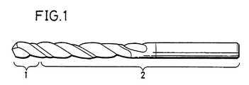
- Fig. 1 shows an exemplary structure of a twist drill.
- the twist drill is formed by a cutting portion 1 which is applied to drilling, and a shank 2 which is not concerned in cutting but mainly adapted to discharge chips and is mounted on a chuck etc. of a cutting machine such as a drilling machine.
- Another drilling tool with an interchangeable cutting insert which is considered to represent the most relevant prior art, is known from the European Patent application EP-A-0 118 806 disclosing a drilling tool comprising a shaft with at least one flute and an interchangeable cutting insert.
- the insert consists of one or two flat tips, each having a main cutting edge. At the narrow side of the tip opposite to the bit there is a fastening spigot having two lateral bearing surfaces and being coaxial to the axis of the drill.
- the insert is fixed to the shank only by utilizing the thrust force, i.e. the force acting in the direction of the rotation axis of the drill as a reaction force against the feeding movement of the drill and the torque.
- the insert is locked with the shank by rotating it in a certain locking position in engagement with recesses provided at the shank. Using this drilling tool, it is possible to change the insert depending on the cutting operation.
- materials for drills are prepared from high-speed steel and cemented carbide.
- the high-speed steel which is excellent in toughness but inferior in wear resistance, is improper for high-speed cutting.
- cemented carbide which is excellent in wear resistance and tool accuracy characteristics but brittle, may cause breakage when the same is applied to a machine tool having low rigidity, for example.
- a cutting portion and a shank of a drill are used under different loaded conditions. Therefore, different characteristics are required for the respective parts of such a drill. For example, wear resistance and adhesion resistance are required for a tip of the cutting portion, while toughness for maintaining strength of the tool is required for the shank. As to the tip of the cutting portion, further, different characteristics are required for central and outer peripheral portions thereof, since these portions are driven at different cutting speeds.
- a drill which is formed by brazing cemented carbide to its cutting portion is not applicable to deep hole drilling of an uncuttable material. If the shank is made of steel, further, significant difference is caused in thermal expansion coefficient between the same and the cemented carbide forming the cutting portion, to easily cause splitting or cracking in brazing.
- an object of the present invention is to provide a throw-away tipped drill comprising an insert which is excellent in wear resistance as well as adhesion resistance and a shank which has sufficient toughness against breakage, with no resharpening for continuous use.
- the aforementioned objects are attained by means of a drill having the features of claim 1 or claim 5.
- Such a throw-away tipped drill comprises an insert for cutting a workpiece and a shank to be mounted on a prescribed position of a cutting machine, and the insert is disengageably mechanically connected with the shank. At least a cutting edge of the insert is formed of a diamond sintered body, and the shank is made of steel.
- the diamond sintered body forming the insert preferably contains diamond in a range of at least 70 volume percent and not more than 99 volume percent.
- the insert may not entirely be formed of a diamond sintered body, but the material therefor may be prepared by bonding a diamond sintered body onto a base of cemented carbide.
- the material therefor may be prepared by bonding a diamond sintered body onto a base of cemented carbide.
- only the cutting edge of the insert may be formed of a diamond sintered body or a material prepared by bonding a diamond sintered body onto a base of cemented carbide, and connected with the remaining portion of the insert, which is made of cemented carbide, by brazing.
- at least the cutting edge of the insert may be formed of a diamond sintered body.
- an insert 31 is fitted in a shank 32 along an arrow as shown in Fig. 2, so that the insert 31 and the shank 32 are connected with each other with no screw or the like, in the so-called self-grip system.
- the insert 31 and the shank 32 are connected with each other by this connection system.
- side portions of a held portion 31a of the insert 31 are brought into contact with inner end surfaces of holding portions 33a and 33b of the shank 32 to cause frictional force, whereby the insert 31 is fixed to the shank 32.
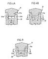
- a coolant supply hole 35 directly supplies a coolant to the cutting edge of the insert 31. Further, a chip breaker 36 is provided on the cutting edge of the insert 31, in order to part chips.
- Fig. 5 shows another example of a shank 32, which is provided with slits 34 not only in a holding portion 33a but in another holding portion 33b.
- an insert 31 is press-fitted in the shank 32 so that both holding portions 33a and 33b are simultaneously expanded, thereby holding a held portion 31a by elastic force thereof.
- Characteristics required for a drill are roughly classified into wear and adhesion resistance for an insert, and breakage resistance, which is represented by toughness, of a shank.
- At least the cutting edge of the insert may be formed of a diamond sintered body, whereby the insert is improved in wear resistance, adhesion resistance and toughness.
- diamond is extremely hard and excellent in high thermal conductivity as compared with WC and Al2O3, which are generally employed as main components for tool materials, and a diamond sintered body is also excellent in toughness.
- the drill is suitable for cutting materials such as cemented carbide, an Al alloy containing a large amount of Si, ceramics, a copper alloy, carbon, and the like.
- the diamond sintered body forming the insert preferably contains diamond in a range of at least 70 volume percent and not more than 99 volume percent since it is impossible to sufficiently improve wear resistance if the content is less than 70 volume percent, while the degree of sintering is deteriorated if the content exceeds 99 volume percent.
- the shank which is made of steel, is excellent in toughness and breakage resistance. Further, the material cost can be reduced.
- the insert and the shank are disengageably mechanically connected with each other, whereby it is possible to easily disengage and throw away the insert, which is relatively damageable and short-lived.
- the throw-away tipped drill comprises an insert for cutting a workpiece and a shank to be mounted on a prescribed position of a cutting machine, and the insert is disengageably mechanically connected with the shank. At least the cutting edge of the insert is formed of a cubic boron nitride sintered body, and the shank is made of steel.
- the cubic boron nitride sintered body forming the insert preferably contains cubic boron nitride in a range of at least 40 volume percent and not more than 80 volume percent.
- the insert may not entirely be formed of a cubic boron nitride sintered body, but the material therefor may be prepared by bonding a cubic boron nitride sintered body onto a base of cemented carbide.
- the cutting edge of the insert may be formed of a cubic boron nitride sintered body or a material obtained by bonding a diamond sintered body onto a base of cemented carbide, and connected with the remaining portion of the insert, which is made of cemented carbide, by brazing.
- at least the cutting edge of the insert may be formed of a cubic boron nitride sintered body.
- the insert and the shank of this throw-away tipped drill can be connected with each other in the system shown in Figs. 2, 3A and 3B, similarly to the above.
- At least the cutting edge of the insert may be formed of a cubic boron nitride sintered body, whereby the insert is improved in wear resistance, adhesion resistance and toughness.
- cubic boron nitride is extremely hard and excellent in thermal conductivity as compared with WC and Al2O3, which are generally employed as main components for tool materials, and a cubic boron nitride sintered body is also excellent in toughness.
- such a cubic boron nitride sintered body is also applicable to working of ferrous materials, particularly very hard steel such as hardened steel, since the same contains no carbon, dissimilarly to diamond.
- the cubic boron nitride sintered body is also capable of cutting an Ni-group or Co-group heat resistant alloy, which is regarded as an uncuttable material, and a ferrous sintered component.
- the cubic boron nitride sintered body which is employed as a material for the insert preferably contains cubic boron nitride in a range of at least 40 volume percent and not more than 80 volume percent since it is impossible to sufficiently improve wear resistance if the content is less than 40 volume percent, while continuity between particles of cubic boron nitride is structurally deteriorated to reduce toughness if the content exceeds 80 volume percent.
- a diamond or cubic boron nitride sintered body is employed as a material for at least the cutting edge of the insert and steel is employed as a material for the shank, whereby the insert is excellent in wear resistance, adhesion resistance and thermal cracking resistance (chipping resistance), while the shank is excellent in toughness and the cost can be relatively reduced.
- the insert is excellent in wear resistance, adhesion resistance and thermal cracking resistance (chipping resistance), while the shank is excellent in toughness and the cost can be relatively reduced.
- the insert and the shank are disengageably mechanically connected with each other, the insert, which is relatively damageable and short-lived, can be easily disengaged from the shank to be thrown away.
- the insert may not be resharpened for continuous use, whereby the cost can be further reduced as compared with the conventional drill, whose insert is inseparably integrated with a shank.
- the drill requires no resharpening of the insert, dispersion of sharpness and tool life is reduced and the overall length of the drill can be maintained constant, with no requirement for measurement of the drill length.
- a base material for the insert can be formed by injection molding, whereby it is possible to easily form a chip breaker or the like, to further reduce the working cost.
- a throw-away tipped drill according to a first embodiment of the present invention is formed by preparing an insert from a material obtained by bonding a diamond sintered body onto a base of cemented carbide and disengageably mechanically connecting the same with a shank of steel in the system shown in Fig. 2.
- Table 1 shows composition values of various powder materials for diamond sintered bodies forming inserts of samples. Table 1 also shows steel materials for shanks of the samples. In the samples shown in Table 1, inserts and shanks are connected with each other in the system shown in Fig. 2. In the samples A to D, the sample D does not fall within the scope of the present invention because the content (volume percent), shown by marks **, of diamond is considerably below the defined range.
- the material for the insert is out of the scope of the present invention in the point that the cutting edge of its insert is formed of coated cemented carbide.
- the material for the cutting edge of the insert is prepared from Si3N4, which is out of the scope of the present invention. Symbol * shows materials which are out of the scope of the present invention respectively.
- Performance evaluation tests for the aforementioned samples were made on drills of 8 mm in diameter, under the following conditions: Workpiece: AC4C Cutting Speed: 120 m/min., dry type (water-soluble cutting oil) Feed Rate: 0.10 mm/rev. Depth of Cut: 25 mm Criterion: Tip conditions etc. were observed after working up to end of life. Life: Generally regarded as ended when the outer peripheral flank was worn by at least 0.2 mm.
- Table 2 shows the results of the aforementioned 15 performance evaluation tests. Excellent results were obtained in the samples A to C embodying the invention as compared with comparative samples E and F. As to the sample D, the number of working holes was reduced and depth of adhesive wear of the inner peripheral face was increased with respect to the same amount of outer peripheral front flank abrasion since the amount of diamond contained in the diamond sintered body forming the insert was less than the range of 70 to 99 volume percent.
- samples of throw-away tipped drills were formed by inserts and shanks of the same materials as those for the sample A of first Example, to compare cutting characteristics as to types of connection systems f26 or the self-grip drill shown in Fig. 2 (sample G), and a comparative sample of a brazed drill, having an insert of cemented carbide, which was out of the scope of the present invention (sample J).
- Cutting conditions were as follows: Workpiece: AC4C Cutting Speed V: 50 m/min. and 150 m/min. (water-soluble cutting oil) Feed Rate: 0.1 mm/rev. Depth of Cut: 40 mm Diameter of Worked Hole: 20 mm Table 3 shows the results of the evaluated characteristics.
- Cutting characteristics represented by stability, can be regarded excellent as horizontal components, thrusts and torque values of cutting balance acting on the drills by cutting resistance are reduced and values of speed dependency are reduced.
- Embodiment 3 of the present invention is now described.
- a throw-away tipped drill according to third embodiment of the present invention is formed by preparing an insert from a material obtained by bonding a cubic boron nitride sintered body onto a base of cemented carbide and disengageably mechanically connecting the same with a shank of steel in the system shown in Fig. 2.
- Table 4 shows composition values of various powder materials for cubic boron nitride sintered bodies forming inserts of samples. Table 4 also shows steel materials for shanks of the samples. In the samples shown in Table 4, inserts and shanks are connected with each other in the system shown in Fig. 2. In the samples K to O, the samples N and O do not fall within the scope of the present invention because the contents (volume percent), shown by marks **, of cubic boron nitride powder materials are out of the defined range of 40 to 80 volume percent.
- the comparative sample P is out of the inventive scope in the point that its shank is made of K30-grade cemented carbide, although its insert is formed of a cubic boron nitride sintered body.
- Table 5 shows the results of the aforementioned 15 performance evaluation tests. Excellent results were obtained as to the samples K to M.
- the samples N and O are somewhat inferior in wear resistance and chipping resistance since the contents of cubic boron nitride in the cubic boron nitride sintered bodies forming the inserts are out of the defined range of 40 to 80 volume percent with respect to bonding phases of cemented carbide.
- Similar experiments were made as to four types of conventional drills as shown in the lower part of Table 5. It is understood from the results that the samples K to M are particularly superior in the samples.
- samples of throw-away tipped drills were formed by inserts and shanks of the same materials as those for the sample K of third embodiment, to compare cutting characteristics as to the connection system for the self-grip drill shown in Fig. 2 (sample Q), and a comparative sample of a brazed drill, having an insert of cemented carbide, which was out of the scope of the present invention (sample T).
- Cutting characteristics represented by stability, can be regarded excellent as horizontal components, thrusts and torque values of cutting balance acting on the drills by cutting resistance are reduced and values of speed dependency are reduced.
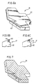
- each insert is prepared from a diamond or cubic boron nitride sintered body, specifically as shown in Fig. 6A, for example, an insert tip 43 of a diamond or cubic boron nitride sintered body is attached to a cutting edge of a base 42, which is made of cemented carbide or steel, of an insert 31.
- a tip piece formed by connecting an insert tip 43 of a diamond or cubic boron nitride sintered body onto a base tip 44 of cemented carbide by burning is engaged with a groove provided in a cutting edge of a base 42 and brazed thereto, as shown in Figs. 6B and 6C.
- the method of manufacturing inserts wherein diamond coating is applied is more preferable, because they can be produced at a low cost by injection molding and complicated figures can be easily formed.
Landscapes
- Engineering & Computer Science (AREA)
- Mechanical Engineering (AREA)
- Drilling Tools (AREA)
Claims (7)
- Foret à embout jetable comprenant un insert (31) pour découper une pièce à usiner et une tige (32) à monter sur une position prescrite de la machine de coupe, cet insert (31) étant raccordé de façon mécaniquement désengageable avec la tige (32), cette tige (32) étant en acier, dans lequel au moins un bord de coupe de l'insert (31) est réalisé en un corps fritté au diamant, la quantité de diamant contenue dans le corps fritté au diamant se situe dans une plage d'au moins 70 % en volume et ne dépasse pas 99 % en volume, ce corps fritté au diamant formant au moins le bord de coupe de l'insert (31) et contient du WC et/ou TiC et Co en plus du diamant, et dans lequel la tige (32) présente des portions de préhension gauche et droite (33a, 33b) à engager avec la portion maintenue (31a) de l'insert (31) pour maintenir celui-ci, chaque portion de préhension ayant une surface d'extrémité interne, une ou deux des portions de maintien étant dotées d'une fente (34) séparant la surface d'extrémité interne de sorte que les surfaces d'extrémité internes opposées sont déplacées sélectivement et sont déformées élastiquement lors de l'engagement entre les portions de préhension et la portion maintenue de sorte que l'insert (31) est fixé sur la tige (32) par une force élastique suivant la déformation élastique des portions de retenue (33a, 33b), provoquée lors de l'engagement de l'insert (31).
- Foret à embout jetable selon la revendication 1, dans lequel l'insert (31) est constitué d'une base (42) en carbure cémenté ou en acier et d'une pointe d'insert (43) fixée sur la base et comprenant un bord de coupe de la base (42), au moins le bord de coupe de la pointe d'insert (43) étant réalisé en un corps fritté au diamant.
- Foret à embout jetable selon la revendication 2, dans lequel la pointe d'insert (43) est fixée sur la base (42) par une pointe de base (44) par brasage.
- Foret à embout jetable selon la revendication 1 ou 2, dans lequel la surface globale de l'insert (31) est revêtue d'une pellicule au diamant.
- Foret à embout jetable comprenant un insert (31) pour couper une pièce à usiner et une tige (32) à monter sur une position prescrite de la machine de coupe, cet insert (31) étant raccordé de façon mécaniquement désengageable avec la tige (32), cette tige (32) étant réalisée en acier, dans lequel au moins un bord tranchant de l'insert (31) est formé à partir d'un corps fritté au nitrure de bore cubique, la quantité de nitrure de bore cubique contenue dans le corps fritté de nitrure de bore cubique formant cet insert se situe dans une plage d'au moins 40 % en volume et ne dépassera pas 80 % en volume, ce corps fritté au nitrure de bore cubique formant au moins le bord tranchant de l'insert (31) et contient au moins l'un de TiC, TiN et WC, et dans lequel la tige (32) présente des portions de préhension gauche et droite (33a, 33b) destinées à coopérer avec une portion retenue (31a) de l'insert (31) pour retenir celui-ci, chaque portion de retenue ayant une surface d'extrémité interne, une ou les deux des portions de retenue étant dotées d'une fente (34) séparant les surfaces d'extrémité internes de sorte que les surfaces d'extrémité internes opposées sont déplacées relativement et déformées élastiquement lors de l'engagement entre les portions de préhension et la portion retenue de sorte que l'insert (31) est fixé sur la tige (32) par force élastique suivant la déformation élastique des portions de retenue (33a, 33b), provoquée lors de l'engagement avec l'insert (31).
- Foret à embout jetable selon la revendication 5, dans lequel l'insert (31) est formé par une base (42) en carbure cémenté ou en acier et une pointe d'insert (43) fixée sur la base et comprenant un bord tranchant de la base (42), au moins le bord de coupe de la pointe d'insert (43) étant formé d'un corps fritté au nitrure de bore cubique.
- Foret à embout jetable selon la revendication 6, dans lequel la pointe d'insert (43) est fixée sur la base (42) par une pointe de base (44) par brasage.
Applications Claiming Priority (4)
| Application Number | Priority Date | Filing Date | Title |
|---|---|---|---|
| JP40645/90 | 1990-02-20 | ||
| JP4064490 | 1990-02-20 | ||
| JP40644/90 | 1990-02-20 | ||
| JP4064590 | 1990-02-20 |
Publications (3)
| Publication Number | Publication Date |
|---|---|
| EP0443517A2 EP0443517A2 (fr) | 1991-08-28 |
| EP0443517A3 EP0443517A3 (en) | 1992-02-12 |
| EP0443517B1 true EP0443517B1 (fr) | 1995-09-06 |
Family
ID=26380134
Family Applications (1)
| Application Number | Title | Priority Date | Filing Date |
|---|---|---|---|
| EP91102345A Expired - Lifetime EP0443517B1 (fr) | 1990-02-20 | 1991-02-19 | Foret à embout jetable |
Country Status (4)
| Country | Link |
|---|---|
| US (1) | US5154550A (fr) |
| EP (1) | EP0443517B1 (fr) |
| KR (1) | KR940005404B1 (fr) |
| DE (1) | DE69112665T2 (fr) |
Cited By (1)
| Publication number | Priority date | Publication date | Assignee | Title |
|---|---|---|---|---|
| US9194189B2 (en) | 2011-09-19 | 2015-11-24 | Baker Hughes Incorporated | Methods of forming a cutting element for an earth-boring tool, a related cutting element, and an earth-boring tool including such a cutting element |
Families Citing this family (36)
| Publication number | Priority date | Publication date | Assignee | Title |
|---|---|---|---|---|
| US5759623A (en) * | 1995-09-14 | 1998-06-02 | Universite De Montreal | Method for producing a high adhesion thin film of diamond on a Fe-based substrate |
| DE19545647A1 (de) * | 1995-12-07 | 1997-06-12 | Hilti Ag | Drehschlag-Wendelbohrer |
| DE19601356A1 (de) * | 1996-01-16 | 1997-07-17 | Plica Werkzeugfabrik Ag | Hartmetallplatte und damit bestückter Gesteinsbohrer sowie Verfahren zu dessen Herstellung |
| DE19757242A1 (de) * | 1997-12-22 | 1999-07-01 | Beck August Gmbh Co | Bohrwerkzeug für Bohrungen in Vollmaterial |
| US6135681A (en) * | 1998-08-21 | 2000-10-24 | Allied Machine & Engineering | Flat bottom tool |
| US6402603B1 (en) | 1998-12-15 | 2002-06-11 | Diamond Machining Technology, Inc. | Two-sided abrasive tool |
| US6261167B1 (en) | 1998-12-15 | 2001-07-17 | Diamond Machining Technology, Inc. | Two-sided abrasive tool and method of assembling same |
| US6528141B1 (en) | 1998-12-15 | 2003-03-04 | Diamond Machining Technology, Inc. | Support structure and method of assembling same |
| AU772301B2 (en) * | 1999-08-03 | 2004-04-22 | Kennametal Inc. | Drill bit having a replaceable cutting head |
| US9199315B2 (en) | 2000-06-02 | 2015-12-01 | Kennametal Inc. | Twist drill and method for producing a twist drill which method includes forming a flute of a twist drill |
| DE10207257B4 (de) * | 2002-02-21 | 2021-02-18 | Kennametal Inc. | Rundlaufschneidwerkzeug mit auswechselbarem Schneideinsatz |
| US7322776B2 (en) * | 2003-05-14 | 2008-01-29 | Diamond Innovations, Inc. | Cutting tool inserts and methods to manufacture |
| JP4782672B2 (ja) | 2003-06-03 | 2011-09-28 | サンドビック インテレクチュアル プロパティー アクティエボラーグ | 割り出し可能な切削インサート及びこの切削インサートの製造方法 |
| US20050183893A1 (en) * | 2004-01-13 | 2005-08-25 | Sandvik Ab | Indexable cutting inserts and methods for producing the same |
| US7309196B2 (en) * | 2004-10-05 | 2007-12-18 | Kennametal Inc. | Modular drill |
| DE102006005379B4 (de) * | 2006-02-03 | 2015-02-12 | Kennametal Inc. | Kombinationswerkzeug und Verfahren zur spanenden Bearbeitung eines Bohrlochs und dessen Bohrungsoberfläche |
| WO2007103939A2 (fr) * | 2006-03-06 | 2007-09-13 | Diamond Innovations, Inc. | Insert d'outil de decoupe a corps d'insert moule |
| US20100285335A1 (en) * | 2007-02-05 | 2010-11-11 | Humphrey Samkelo Lungisani Sithebe | Polycrystalline diamond (pcd) materials |
| US9139893B2 (en) | 2008-12-22 | 2015-09-22 | Baker Hughes Incorporated | Methods of forming bodies for earth boring drilling tools comprising molding and sintering techniques |
| US8505654B2 (en) * | 2009-10-09 | 2013-08-13 | Element Six Limited | Polycrystalline diamond |
| CN101949264A (zh) * | 2010-07-02 | 2011-01-19 | 大庆油田有限责任公司 | 一种井下水平钻孔用金刚石钻头及其制作方法 |
| EP2614906B1 (fr) * | 2010-09-07 | 2020-07-15 | Sumitomo Electric Hardmetal Corp. | Outil de coupe |
| US9010464B2 (en) | 2011-05-04 | 2015-04-21 | Dover BMCS Acquistion Corporation | Drill bits and drilling apparatuses including the same |
| US9662717B2 (en) * | 2011-05-23 | 2017-05-30 | Sharon-Cutwell Co., Inc. | Drilling tool |
| US20120308319A1 (en) * | 2011-06-03 | 2012-12-06 | Karthik Sampath | Rotary cutting tool having coated cutting tip and coolant holes and method of fabricating |
| DE102013205889B3 (de) | 2013-04-03 | 2014-05-28 | Kennametal Inc. | Kupplungsteil, insbesondere Schneidkopf für ein Rotationswerkzeug sowie ein derartiges Rotationswerkzeug |
| DE102013220884B4 (de) | 2013-10-15 | 2022-02-17 | Kennametal Inc. | Modulares Trägerwerkzeug sowie Werkzeugkopf |
| DE102014206796B4 (de) | 2014-04-08 | 2020-10-15 | Kennametal Inc. | Rotationswerkzeug, insbesondere Bohrer sowie Schneidkopf für ein solches Rotationswerkzeug |
| DE102015211744B4 (de) | 2015-06-24 | 2023-07-20 | Kennametal Inc. | Rotationswerkzeug, insbesondere Bohrer, und Schneidkopf für ein solches Rotationswerkzeug |
| US9937567B2 (en) | 2015-10-07 | 2018-04-10 | Kennametal Inc. | Modular drill |
| USD798922S1 (en) | 2015-10-07 | 2017-10-03 | Kennametal Inc. | Cutting head for rotary drill |
| US10071430B2 (en) | 2015-10-07 | 2018-09-11 | Kennametal Inc. | Cutting head, rotary tool and support for the rotary tool and for the accommodation of the cutting head |
| USD798921S1 (en) | 2015-10-07 | 2017-10-03 | Kennametal Inc. | Cutting head for modular drill |
| US10799958B2 (en) | 2017-08-21 | 2020-10-13 | Kennametal Inc. | Modular rotary cutting tool |
| CN112077370B (zh) | 2019-06-13 | 2024-10-01 | 肯纳金属印度有限公司 | 可转位钻头刀片 |
| CN115703157A (zh) | 2021-08-17 | 2023-02-17 | 肯纳金属印度有限公司 | 具有冷却剂系统的可转位钻头组件 |
Citations (2)
| Publication number | Priority date | Publication date | Assignee | Title |
|---|---|---|---|---|
| DE262345C (fr) * | ||||
| US4714385A (en) * | 1986-02-27 | 1987-12-22 | General Electric Company | Polycrystalline diamond and CBN cutting tools |
Family Cites Families (24)
| Publication number | Priority date | Publication date | Assignee | Title |
|---|---|---|---|---|
| US3540323A (en) * | 1968-06-17 | 1970-11-17 | Caterpillar Tractor Co | Drill having indexable carbide inserts |
| AU518306B2 (en) * | 1977-05-04 | 1981-09-24 | Sumitomo Electric Industries, Ltd. | Sintered compact for use ina cutting tool anda method of producing thesame |
| JPS6039739B2 (ja) * | 1979-01-13 | 1985-09-07 | 日本特殊陶業株式会社 | 高密度立方晶窒化硼素焼結体 |
| EP0081775B1 (fr) * | 1981-12-16 | 1986-04-09 | General Electric Company | Matériau composite extra-dur nitruré |
| JPS58143115A (ja) * | 1982-02-19 | 1983-08-25 | Akira Mineshige | 自動車エンジンの廃熱利用方法 |
| DE3306209C2 (de) * | 1983-02-23 | 1985-02-28 | Iscar Hartmetall GmbH, 7505 Ettlingen | Bohrwerkzeug mit auswechselbarem Schneideinsatz |
| US4527931A (en) * | 1983-05-27 | 1985-07-09 | Gte Laboratories Incorporated | Indexable insert for mining drill |
| JPS60122785A (ja) * | 1983-12-08 | 1985-07-01 | 三菱マテリアル株式会社 | ダイヤモンド被覆工具部材 |
| CA1248519A (fr) * | 1984-04-03 | 1989-01-10 | Tetsuo Nakai | Outil composite, et sa fabrication |
| SE454421B (sv) * | 1984-07-12 | 1988-05-02 | Sandvik Ab | Borr med utbytbar borrspets |
| JPS61136702A (ja) * | 1984-12-07 | 1986-06-24 | Hitachi Ltd | 切削工具 |
| JPS6246489A (ja) * | 1985-08-23 | 1987-02-28 | Nippon Texas Instr Kk | ダイナミツク型差動増幅器 |
| JPS62218010A (ja) * | 1986-03-19 | 1987-09-25 | Mitsubishi Metal Corp | 超硬ドリル |
| JPH0777688B2 (ja) * | 1986-06-09 | 1995-08-23 | 三菱マテリアル株式会社 | 耐欠損性のすぐれたサーメット製ドリル |
| JPS6338502A (ja) * | 1986-08-05 | 1988-02-19 | Sumitomo Metal Mining Co Ltd | 複合超硬合金及びその製造方法 |
| JPS6338501A (ja) * | 1986-08-05 | 1988-02-19 | Sumitomo Metal Mining Co Ltd | 複合超硬合金及びその製造方法 |
| DE3772671D1 (de) * | 1986-08-11 | 1991-10-10 | Sumitomo Electric Industries | Aluminiumoxyd, beschichtet mit diamant. |
| DE3864075D1 (de) * | 1987-05-20 | 1991-09-12 | Sumitomo Electric Industries | Abstechwerkzeug. |
| JPH01153228A (ja) * | 1987-12-10 | 1989-06-15 | Asahi Daiyamondo Kogyo Kk | 気相合成ダイヤモンド工具の製造法 |
| JPH01164701A (ja) * | 1987-12-18 | 1989-06-28 | Chiyoda Kagaku Kenkyusho:Kk | 次亜塩素酸ナトリウム水溶液の安定化法 |
| IE61697B1 (en) * | 1987-12-22 | 1994-11-16 | De Beers Ind Diamond | Abrasive product |
| EP0356097B1 (fr) * | 1988-08-15 | 1994-11-23 | De Beers Industrial Diamond Division (Proprietary) Limited | Elément rapporté pour outil |
| JP2744957B2 (ja) * | 1988-09-30 | 1998-04-28 | 矢崎総業株式会社 | フラットワイヤハーネス及びその製造方法 |
| FR2638461A1 (fr) * | 1988-11-03 | 1990-05-04 | Combustible Nucleaire | Produit composite abrasif comportant une partie active de materiau ultra-dur et procede de fabrication d'un tel produit |
-
1991
- 1991-02-19 EP EP91102345A patent/EP0443517B1/fr not_active Expired - Lifetime
- 1991-02-19 DE DE69112665T patent/DE69112665T2/de not_active Expired - Fee Related
- 1991-02-20 KR KR1019910002690A patent/KR940005404B1/ko not_active Expired - Fee Related
-
1992
- 1992-03-30 US US07/860,102 patent/US5154550A/en not_active Expired - Fee Related
Patent Citations (2)
| Publication number | Priority date | Publication date | Assignee | Title |
|---|---|---|---|---|
| DE262345C (fr) * | ||||
| US4714385A (en) * | 1986-02-27 | 1987-12-22 | General Electric Company | Polycrystalline diamond and CBN cutting tools |
Cited By (2)
| Publication number | Priority date | Publication date | Assignee | Title |
|---|---|---|---|---|
| US9194189B2 (en) | 2011-09-19 | 2015-11-24 | Baker Hughes Incorporated | Methods of forming a cutting element for an earth-boring tool, a related cutting element, and an earth-boring tool including such a cutting element |
| US9771497B2 (en) | 2011-09-19 | 2017-09-26 | Baker Hughes, A Ge Company, Llc | Methods of forming earth-boring tools |
Also Published As
| Publication number | Publication date |
|---|---|
| EP0443517A3 (en) | 1992-02-12 |
| KR940005404B1 (ko) | 1994-06-18 |
| DE69112665T2 (de) | 1996-04-04 |
| US5154550A (en) | 1992-10-13 |
| DE69112665D1 (de) | 1995-10-12 |
| EP0443517A2 (fr) | 1991-08-28 |
Similar Documents
| Publication | Publication Date | Title |
|---|---|---|
| EP0443517B1 (fr) | Foret à embout jetable | |
| EP0441302B1 (fr) | Foret à plaquette jetable | |
| EP0460237B1 (fr) | Foret jetable | |
| US5137398A (en) | Drill bit having a diamond-coated sintered body | |
| US5186739A (en) | Cermet alloy containing nitrogen | |
| US4971485A (en) | Cemented carbide drill | |
| EP1152858B1 (fr) | Outil et tete coupante pour dispositif d'usinage par enlevement de matiere | |
| EP1590120B1 (fr) | Fraise a bords tranchants convexes | |
| EP0983814A2 (fr) | Outil de coupe | |
| US20060045640A1 (en) | Support pads for drill heads | |
| CN113710394A (zh) | 刀片以及具备该刀片的切削刀具 | |
| EP0454114B1 (fr) | Foret à corps fritté et à revêtement de diamant | |
| US6152660A (en) | Drilling tool for bores in solid material | |
| JPH0343112A (ja) | 焼結硬質合金製ドリル | |
| WO1994008745A1 (fr) | Fraise a deux tailles a axe vertical possedant une ame de materiaux composes et un revetement en materiau dur | |
| JPH04217414A (ja) | スローアウェイ式ドリル | |
| KR940005402B1 (ko) | 드로우어웨이식 드릴 | |
| KR930011657B1 (ko) | 드로우 어웨이식 드릴 | |
| JPH04217413A (ja) | スローアウェイ式ドリル | |
| JPH04217412A (ja) | スローアウェイ式ドリル | |
| JPH04304916A (ja) | スローアウェイ式ドリル | |
| KR200336499Y1 (ko) | 공구수명 향상을 위한 솔리드형 초경 버니싱 드릴 | |
| JPS6225293Y2 (fr) | ||
| JPH0349813A (ja) | 焼結硬質合金製ドリル | |
| Hoshi et al. | High Performance Drill Geometry. I |
Legal Events
| Date | Code | Title | Description |
|---|---|---|---|
| PUAI | Public reference made under article 153(3) epc to a published international application that has entered the european phase |
Free format text: ORIGINAL CODE: 0009012 |
|
| AK | Designated contracting states |
Kind code of ref document: A2 Designated state(s): DE FR GB IT SE |
|
| PUAL | Search report despatched |
Free format text: ORIGINAL CODE: 0009013 |
|
| AK | Designated contracting states |
Kind code of ref document: A3 Designated state(s): DE FR GB IT SE |
|
| 17P | Request for examination filed |
Effective date: 19920325 |
|
| 17Q | First examination report despatched |
Effective date: 19930326 |
|
| GRAA | (expected) grant |
Free format text: ORIGINAL CODE: 0009210 |
|
| AK | Designated contracting states |
Kind code of ref document: B1 Designated state(s): DE FR GB IT SE |
|
| PG25 | Lapsed in a contracting state [announced via postgrant information from national office to epo] |
Ref country code: IT Free format text: LAPSE BECAUSE OF FAILURE TO SUBMIT A TRANSLATION OF THE DESCRIPTION OR TO PAY THE FEE WITHIN THE PRE;WARNING: LAPSES OF ITALIAN PATENTS WITH EFFECTIVE DATE BEFORE 2007 MAY HAVE OCCURRED AT ANY TIME BEFORE 2007. THE CORRECT EFFECTIVE DATE MAY BE DIFFERENT FROM THE ONE RECORDED.SCRIBED TIME-LIMIT Effective date: 19950906 Ref country code: FR Effective date: 19950906 |
|
| REF | Corresponds to: |
Ref document number: 69112665 Country of ref document: DE Date of ref document: 19951012 |
|
| PG25 | Lapsed in a contracting state [announced via postgrant information from national office to epo] |
Ref country code: SE Effective date: 19951206 |
|
| EN | Fr: translation not filed | ||
| REG | Reference to a national code |
Ref country code: GB Ref legal event code: 746 Effective date: 19960319 |
|
| PLBE | No opposition filed within time limit |
Free format text: ORIGINAL CODE: 0009261 |
|
| STAA | Information on the status of an ep patent application or granted ep patent |
Free format text: STATUS: NO OPPOSITION FILED WITHIN TIME LIMIT |
|
| 26N | No opposition filed | ||
| REG | Reference to a national code |
Ref country code: GB Ref legal event code: IF02 |
|
| PGFP | Annual fee paid to national office [announced via postgrant information from national office to epo] |
Ref country code: GB Payment date: 20030219 Year of fee payment: 13 |
|
| PGFP | Annual fee paid to national office [announced via postgrant information from national office to epo] |
Ref country code: DE Payment date: 20030227 Year of fee payment: 13 |
|
| PG25 | Lapsed in a contracting state [announced via postgrant information from national office to epo] |
Ref country code: GB Free format text: LAPSE BECAUSE OF NON-PAYMENT OF DUE FEES Effective date: 20040219 |
|
| PG25 | Lapsed in a contracting state [announced via postgrant information from national office to epo] |
Ref country code: DE Free format text: LAPSE BECAUSE OF NON-PAYMENT OF DUE FEES Effective date: 20040901 |
|
| GBPC | Gb: european patent ceased through non-payment of renewal fee |
Effective date: 20040219 |