EP0443773B1 - Metallschneidwerkzeug - Google Patents
Metallschneidwerkzeug Download PDFInfo
- Publication number
- EP0443773B1 EP0443773B1 EP91301171A EP91301171A EP0443773B1 EP 0443773 B1 EP0443773 B1 EP 0443773B1 EP 91301171 A EP91301171 A EP 91301171A EP 91301171 A EP91301171 A EP 91301171A EP 0443773 B1 EP0443773 B1 EP 0443773B1
- Authority
- EP
- European Patent Office
- Prior art keywords
- tubular
- shim
- insert
- base portion
- cutting tool
- Prior art date
- Legal status (The legal status is an assumption and is not a legal conclusion. Google has not performed a legal analysis and makes no representation as to the accuracy of the status listed.)
- Expired - Lifetime
Links
Images


Classifications
-
- B—PERFORMING OPERATIONS; TRANSPORTING
- B23—MACHINE TOOLS; METAL-WORKING NOT OTHERWISE PROVIDED FOR
- B23C—MILLING
- B23C5/00—Milling-cutters
- B23C5/16—Milling-cutters characterised by physical features other than shape
- B23C5/20—Milling-cutters characterised by physical features other than shape with removable cutter bits or teeth or cutting inserts
- B23C5/22—Securing arrangements for bits or teeth or cutting inserts
- B23C5/2204—Securing arrangements for bits or teeth or cutting inserts with cutting inserts clamped against the walls of the recess in the cutter body by a clamping member acting upon the wall of a hole in the insert
- B23C5/2208—Securing arrangements for bits or teeth or cutting inserts with cutting inserts clamped against the walls of the recess in the cutter body by a clamping member acting upon the wall of a hole in the insert for plate-like cutting inserts
-
- B—PERFORMING OPERATIONS; TRANSPORTING
- B23—MACHINE TOOLS; METAL-WORKING NOT OTHERWISE PROVIDED FOR
- B23C—MILLING
- B23C2210/00—Details of milling cutters
- B23C2210/16—Fixation of inserts or cutting bits in the tool
- B23C2210/166—Shims
-
- Y—GENERAL TAGGING OF NEW TECHNOLOGICAL DEVELOPMENTS; GENERAL TAGGING OF CROSS-SECTIONAL TECHNOLOGIES SPANNING OVER SEVERAL SECTIONS OF THE IPC; TECHNICAL SUBJECTS COVERED BY FORMER USPC CROSS-REFERENCE ART COLLECTIONS [XRACs] AND DIGESTS
- Y10—TECHNICAL SUBJECTS COVERED BY FORMER USPC
- Y10T—TECHNICAL SUBJECTS COVERED BY FORMER US CLASSIFICATION
- Y10T407/00—Cutters, for shaping
- Y10T407/19—Rotary cutting tool
- Y10T407/1906—Rotary cutting tool including holder [i.e., head] having seat for inserted tool
- Y10T407/1908—Face or end mill
- Y10T407/192—Face or end mill with separate means to fasten tool to holder
-
- Y—GENERAL TAGGING OF NEW TECHNOLOGICAL DEVELOPMENTS; GENERAL TAGGING OF CROSS-SECTIONAL TECHNOLOGIES SPANNING OVER SEVERAL SECTIONS OF THE IPC; TECHNICAL SUBJECTS COVERED BY FORMER USPC CROSS-REFERENCE ART COLLECTIONS [XRACs] AND DIGESTS
- Y10—TECHNICAL SUBJECTS COVERED BY FORMER USPC
- Y10T—TECHNICAL SUBJECTS COVERED BY FORMER US CLASSIFICATION
- Y10T407/00—Cutters, for shaping
- Y10T407/19—Rotary cutting tool
- Y10T407/1906—Rotary cutting tool including holder [i.e., head] having seat for inserted tool
- Y10T407/1934—Rotary cutting tool including holder [i.e., head] having seat for inserted tool with separate means to fasten tool to holder
-
- Y—GENERAL TAGGING OF NEW TECHNOLOGICAL DEVELOPMENTS; GENERAL TAGGING OF CROSS-SECTIONAL TECHNOLOGIES SPANNING OVER SEVERAL SECTIONS OF THE IPC; TECHNICAL SUBJECTS COVERED BY FORMER USPC CROSS-REFERENCE ART COLLECTIONS [XRACs] AND DIGESTS
- Y10—TECHNICAL SUBJECTS COVERED BY FORMER USPC
- Y10T—TECHNICAL SUBJECTS COVERED BY FORMER US CLASSIFICATION
- Y10T407/00—Cutters, for shaping
- Y10T407/22—Cutters, for shaping including holder having seat for inserted tool
- Y10T407/2272—Cutters, for shaping including holder having seat for inserted tool with separate means to fasten tool to holder
- Y10T407/2274—Apertured tool
- Y10T407/2276—Apertured tool with means projecting through aperture to force tool laterally against reaction surface
Definitions
- This invention relates to a metal cutting tool according to the precharacterising part of claim 1 consisting of a tool holder and at least one cutting insert releasably retained within a pocket formed in the tool holder.
- the invention relates also to an insert shim according to the precharacterising part of claim 9.
- the or each cutting insert is releasably retained in a respective pocket formed in a tool holder by, for example, a clamping screw which extends through a central hole formed in the insert into an appropriate tapped bore formed in the tool holder or, alternatively, by some other suitable clamping system.
- a metal shim is interposed between the insert and the bottom wall of the tool holder pocket, this shim serving to protect the tool holder proper from excessive wear or damage through use.
- shims of differing heights can be employed so as to vary as required the specific location of the cutting insert with respect to the tool holder and in particular that of the cutting edge.
- FR-A 2 218 154 discloses a cutting tool having a tool holder in which is formed a pocket and wherein a cutting insert is screw clamped to the tool holder via an interposed seating shim.
- This seating shim is retained in position on the tool holder by means of a split tubular retaining means which extends into a tubular cavity in the tool holder and which is formed, at an outer end thereof, with an outwardly extending flange which is located within a peripheral recess formed in the seatihg shim.
- a metal cutting tool comprising a tool holder; a pocket in said tool holder defined by side and base walls; an elongated tubular recess formed in said tool holder and opening into said pocket; an insert seating shim having a planar base surface and supported on said base wall; a cutting insert supported on said base surface; characterised in that there is provided a split, tubular coupling element formed integrally with said shim and insertable upon spring-like compression thereof into said tubular recess so as to be retained therein.
- an insert shim having the features of claim 9.
- the insert seating shim is integrally formed with means (the split, tubular coupling portion) facilitating its ready, secure, releasable mounting in the tool holder pocket without the necessity of providing for separate retaining means.
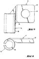
- FIG. 1, 2 and 3 of the drawings illustrate the application of the invention to a cutting tool in the form of a substantially standard milling cutter head 1 which is formed with a plurality of peripherally distributed recesses 2, each recess having formed therein an insert retaining pocket 3 shown clearly in Fig. 3 of the drawings.
- Each pocket 3 is defined by a pair of side walls 4 and 5 and a base wall 6.
- An elongated tubular recess 7 is formed at the junction of the side wall 5 and the base wall 6 and opens into the pocket 3 via an elongated slot 8 which is codirectional with the linear junction of the side wall 5 and the base wall 6. Extending centrally into the base wall 6 is a tapped aperture 9.
- An insert seating shim 11 is constituted by a substantially rectangular planar base portion 12 having outer, base and side surfaces and which substantially corresponds in shape and area to the base wall 6 of the pocket 3 and in which is formed a central, through-going aperture 13.
- a split, tubular side portion 14 Formed integrally with a side edge of the base portion 12 is a split, tubular side portion 14 which is coextensive with the edge to which it is connected.
- Fig. 2 shows the milling head provided with cutting inserts, each of which is seated on a seating shim of the kind shown and described with reference to Fig. 3 of the drawings.
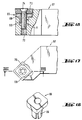
- Figs. 6 and 7 of the drawings show a modified form of seating shim 21 having, as before, a substantially planar, rectangular base portion 22 and a split, tubular side portion 23. Additionally, the seating shim is formed integrally with an edge thereof perpendicular to the tubular side portion 23 with an abutment shoulder 24 against which an insert 25 is designed to abut when the shim is retainingly placed in position in the pocket 3.
- an insert seating shim 31 comprises a substantially rectangular base portion 32 having a through-going aperture 33 and having a split, tubular side portion 34 formed integrally with a side edge thereof.
- the tubular side portion 34 is not coextensive with the edge of the base portion with which it is integral, but is constituted by a first section 35 which is formed integrally with a portion of the side edge of the base portion 32 and a second section 36 which projects beyond the side edge of the base portion 32.
- a tool pocket 3′ is formed with an inwardly extending tubular recess 37 into which the tubular side portion section 36 is inserted so as to retain in position the shim 31 within the pocket 3′.
- the tubular side portion section 36 constitutes an abutment shoulder for an insert 15 which rests on the seating shim 31 and is secured thereto by the clamping screw 16.
- the seating shim together with its integrally formed side portion are produced by suitable casting, in the embodiment shown in Figs. 12, 13 and 14 of the drawings a seating shim blank 41 constituted by a substantially rectangular base portion 42, with which is integrally formed a side blank 43 also of substantially rectangular shape.
- the side blank 43 is joined to the base portion 42 via an intermediate tapering portion 44.
- Fig. 14 of the drawings when the side blank 43 is bent into a substantially circular shape, it effectively constitutes the split, tubular side portion which can be used, upon insertion into a corresponding tubular recess, for the retention of the seating shim in the pocket.
- a seating shim 51 is formed with a split tubular coupling element 52 which is integral with a corner of the seating shim 51 via a neck portion 53.
- a tool holder 54 is formed with a retaining pocket 55 defined by a base wall 56 and a pair of side walls 57 and 58. At the intersection of the walls 57 and 58 is formed a tubular recess 59 which opens into the pocket via a narrow slot 60.
- the tubular coupling element 52 is springily compressed and is inserted into the tubular recess 59 with the neck portion 53 projecting through the slot 60.
- the seating shim 51 is securely retained within the pocket 55 and is ready to have placed thereon a cutting insert 61 which is clamped thereto and to the tool holder 54 by means of a clamping screw 62.
- a seating shim 65 is formed with a central, downwardly depending, split tubular coupling element 66.
- a tool holder 67 (in this example, of a turning or grooving tool) is formed with a pocket having a base wall 68 and a pair of side walls 69 and 70.
- a tubular recess 71 is formed in the base wall 68 corresponding in cross-sectional shape to that of the coupling element 66, this tubular recess being coaxial with and constituting an extension of a tapped clamping bore 72.
- the seating shim 65 is placed in position within the pocket by springily compressing the tubular coupling element 66 which is then inserted into the correspondingly shaped tubular recess 71 to prevent relative rotational displacement of the seating shim 65 with respect to the tool holder 67.
- a cutting insert 73 is placed on the seating shim 65 with a pair of side walls thereof abutting the side walls 69 and 70 of the pocket. The insert 73 and seating shim 65 are then clamped in position by means of a clamping screw 74 which is screwed into the clamping bore 72.
- the cutting insert can be provided with an integrally formed split tubular coupling element which can be retained within a corresponding tubular recess formed in the tool holder.
- inserts with integrally formed, split tubular coupling elements corresponding in general shape to the shims shown in Figs. 4, 5; Fig. 15; and Figs. 16, 17 and 18, can be employed.
Landscapes
- Engineering & Computer Science (AREA)
- Mechanical Engineering (AREA)
- Cutting Tools, Boring Holders, And Turrets (AREA)
- Milling Processes (AREA)
Claims (15)
- Metallschneidwerkzeug mit einem Werkzeughalter (1, 54, 67), einem im Werkzeughalter (1, 54, 67) durch Seitenwände und eine Basiswand (4, 5, 6, 56, 57, 58, 68, 69, 70) definierten Aufnahmeabschnitt (3, 3′, 55), einer im Werkzeughalter (1, 54, 67) ausgebildeten und sich in den Aufnahmeabschnitt (3, 3′, 55) öffnenden länglichen, rohrförmigen Vertiefung (7, 37, 59, 71), einem an der Basiswand (6, 56, 68) gehaltenen Einsatz-Befestigungsflächenabstandsstück (11, 21, 31, 51, 65) mit einer flachen Basisfläche (12, 32), und einem an der Basisfläche (12, 32) gehaltenen Schneideinsatz (15, 61), dadurch gekennzeichnet, daß ein mit dem Abstandsstück einstückig ausgebildetes gespaltenes, rohrförmiges Verbindungselement (14, 23, 34, 52, 66) vorgesehen ist, das durch federähnliches Zusammendrücken in die rohrförmige Vertiefung (7, 37, 59, 71) eingesetzt werden kann, um darin gehalten zu werden.
- Metallschneidwerkzeug nach Anspruch 1, dadurch gekennzeichnet, daß das Einsatz-Befestigungsflächenabstandsstück (11, 21, 31, 51) ein gespaltenes, rohrförmiges Verbindungselement (14, 23, 34, 52) aufweist, das mit Seitenrändern des Abstandsstücks einstückig ausgebildet ist.
- Metallschneidwerkzeug nach Anspruch 2, dadurch gekennzeichnet, daß das gespaltene, rohrförmige Verbindungselement (14, 23, 34) mit einem Seitenrand des Abstandsstücks einstückig ausgebildet ist.
- Metallschneidwerkzeug nach Anspruch 3, dadurch gekennzeichnet, daß die Vertiefung (7) sich über einen länglichen Schlitz (8), der an eine gerade verbindungslinie der Basiswand (6) und einer Seitenwand (4, 5) angrenzt und in der gleichen Richtung verläuft wie die Verbindungslinie, in den Aufnahmeabschnitt (3) öffnet, wobei der flache Basisabschnitt (12, 22) sich durch den Schlitz erstreckt.
- Metallschneidwerkzeug nach Anspruch 4, dadurch gekennzeichnet, daß der flache Basisabschnitt (22) an einem Seitenrand eine quer zum rohrförmigen Seitenabschnitt (23) angeordnete Einsatz-Anschlagschulter (24) aufweist.
- Metallschneidwerkzeug nach Anspruch 3, dadurch gekennzeichnet, daß die Vertiefung (37) sich in einer Richtung vom Aufnahmeabschnitt (3′, 55) weg in den Werkzeughalter (1) erstreckt, und wobei der rohrförmige Seitenabschnitt (34) einen ersten Bereich (36), der sich über den Basisabschnitt (32) hinaus erstreckt und elastisch in die Vertiefung (37) einsetzbar ist, und einen zweiten Bereich (35) aufweist, der sich entlang mindestens eines Teils der Länge des zuerst erwähnten Seitenrands des Basisabschnitts (32) erstreckt und eine Einsatzanschlagschulter bildet.
- Metallschneidwerkzeug nach Anspruch 2, dadurch gekennzeichnet, daß der flache Basisabschnitt an einer Ecke davon das gespaltene, rohrförmige Verbindungselement (52) aufweist.
- Metallschneidwerkzeug nach Anspruch 1, dadurch gekennzeichnet, daß das Befestigungsflächenabstandsstück (65) das gespaltene, rohrförmige Verbindungselement (66) aufweist, das sich bezüglich einer flachen Basisseite davon mittig und nach unten erstreckt, und wobei die längliche, rohrförmige Vertiefung (71) in einer Basisfläche (68) des Werkzeughalters (67) ausgebildet ist.
- Einsatz-Befestigungsflächenabstandsstück (11, 21, 31) zur Verwendung mit einem Metallschneidwerkzeug nach einem der Ansprüche 1 bis 6, wobei das Abstandsstück einen flachen Basisabschnitt (12, 22, 32) aufweist, dadurch gekennzeichnet, daß ein gespaltener, rohrförmiger Abschnitt (14, 23, 34) mit dem Abstandsstück einstückig ausgebildet ist.
- Abstandsstück (11, 21, 31) nach Anspruch 9, dadurch gekennzeichnet, daß der rohrförmige Abschnitt (14, 23, 34) mit einem Seitenrand des Basisabschnitts (12, 22, 32) einstückig ausgebildet ist.
- Abstandsstück (11, 21, 31) nach Anspruch 10, dadurch gekennzeichnet, daß der flache Basisabschnitt (22) an einem Seitenrand davon eine quer zum rohrförmigen Seitenabschnitt (23) angeordnete Einsatzanschlagschulter (24) aufweist.
- Abstandsstück nach Anspruch 10, dadurch gekennzeichnet, daß der rohrförmige Seitenabschnitt (34) einen ersten Bereich (36), der sich über den Basisabschnitt (32) hinaus erstreckt, und einen zweiten Bereich (35) aufweist, der sich entlang mindestens eines Teils der Länge des zuerst erwähnten Seitenrands des Basisabschnitts (32) erstreckt und eine Einsatzanschlagschulter bildet.
- Abstandsstück nach einem der Ansprüche 10, 11 oder 12, dadurch gekennzeichnet, daß im Basisabschnitt (12) eine Durchgangsöffnung (13) ausgebildet ist.
- Abstandsstück (51) nach Anspruch 9, dadurch gekennzeichnet, daß das gespaltene, rohrförmige Verbindungselement an einer Ecke des flachen Basisabschnitts ausgebildet ist.
- Abstandsstück (65) nach Anspruch 9, dadurch gekennzeichnet, daß es ein sich davon mittig erstreckendes gespaltenes, rohrförmiges Verbindungselement (66) aufweist.
Applications Claiming Priority (2)
| Application Number | Priority Date | Filing Date | Title |
|---|---|---|---|
| GB909003697A GB9003697D0 (en) | 1990-02-19 | 1990-02-19 | A metal cutting tool |
| GB9003697 | 1990-02-19 |
Publications (3)
| Publication Number | Publication Date |
|---|---|
| EP0443773A2 EP0443773A2 (de) | 1991-08-28 |
| EP0443773A3 EP0443773A3 (en) | 1991-10-16 |
| EP0443773B1 true EP0443773B1 (de) | 1994-07-27 |
Family
ID=10671235
Family Applications (1)
| Application Number | Title | Priority Date | Filing Date |
|---|---|---|---|
| EP91301171A Expired - Lifetime EP0443773B1 (de) | 1990-02-19 | 1991-02-13 | Metallschneidwerkzeug |
Country Status (9)
| Country | Link |
|---|---|
| US (1) | US5129767A (de) |
| EP (1) | EP0443773B1 (de) |
| JP (1) | JP2603370B2 (de) |
| AU (1) | AU641724B2 (de) |
| DE (1) | DE69103038T2 (de) |
| GB (1) | GB9003697D0 (de) |
| IL (1) | IL96962A (de) |
| RU (1) | RU1838051C (de) |
| ZA (1) | ZA91890B (de) |
Families Citing this family (14)
| Publication number | Priority date | Publication date | Assignee | Title |
|---|---|---|---|---|
| DE4325999C2 (de) * | 1993-08-03 | 1996-02-15 | Walter Ag | Rundlaufendes Schneidwerkzeug mit Wendeplattenbestückung, insbesondere zur Metallbearbeitung |
| IL112818A (en) * | 1995-02-28 | 1999-10-28 | Iscar Ltd | Tool holder having a grooved seat |
| IL117015A (en) * | 1996-02-02 | 1998-12-27 | Iscar Ltd | Cutting Tools |
| SE512736C2 (sv) * | 1997-06-10 | 2000-05-08 | Seco Tools Ab | Planfräsningsverktyg |
| SE9803111L (sv) * | 1998-06-15 | 2000-03-16 | Seco Tools Ab | Metod |
| IL127175A (en) * | 1998-11-20 | 2003-06-24 | Iscar Ltd | Cutting insert for mounting on a milling cutter |
| US6511264B2 (en) * | 2001-02-01 | 2003-01-28 | Ingersoll Cutting Tool Company | Adjustable insert seat |
| SE523655C2 (sv) * | 2001-08-09 | 2004-05-04 | Sandvik Ab | Roterbart skärverktyg med ett skär som är fastspännbart med en partiellt böjlig spännskruv. |
| US8308400B2 (en) * | 2007-03-30 | 2012-11-13 | Kyocera Corporation | Sheet member, rotary tool using the sheet member, and cutting method using the rotary tool |
| DE102008001857A1 (de) * | 2007-05-22 | 2008-11-27 | Ceramtec Ag | Plattensitz mit Einlegestücken |
| US8974154B2 (en) | 2011-03-11 | 2015-03-10 | Sandvik Intellectual Property Ab | Cutting insert and shim for milling cutters |
| EP2596887B1 (de) | 2011-11-23 | 2019-01-23 | Sandvik Intellectual Property AB | Schneidwerkzeug mit austauschbarem Einsatzsitzelement |
| SE536881C2 (sv) | 2013-02-06 | 2014-10-14 | Sandvik Intellectual Property | Anordning för spånavskiljande bearbetning försedd med underläggsplatta |
| EP3246117A1 (de) * | 2016-05-20 | 2017-11-22 | Seco Tools Ab | Schneidwerkzeug und unterlegscheibe |
Family Cites Families (12)
| Publication number | Priority date | Publication date | Assignee | Title |
|---|---|---|---|---|
| SE312962B (de) * | 1964-10-21 | 1969-07-28 | Fagersta Bruks Ab | |
| US3246382A (en) * | 1964-11-13 | 1966-04-19 | Frank P Zierden | Adapter for seating carbide cutters |
| DE1602721A1 (de) * | 1967-09-14 | 1970-05-14 | Krupp Gmbh | Spanabhebendes Werkzeug |
| SE362369B (de) * | 1973-02-21 | 1973-12-10 | Sandvik Ab | |
| SU629006A1 (ru) * | 1974-06-28 | 1978-10-25 | Radoshchekin Gavriil A | Резец |
| US4011049A (en) * | 1975-09-19 | 1977-03-08 | Kennametal Inc. | Method of and device for holding a cutting insert in the pocket of a tool holder |
| US4202650A (en) * | 1978-10-13 | 1980-05-13 | Kennametal Inc. | Shim lock toolholder |
| SU844130A1 (ru) * | 1979-01-12 | 1981-07-07 | Golubev Evgenij M | Сборный резец |
| US4329091A (en) * | 1980-05-07 | 1982-05-11 | General Electric Company | Floating wedge for use in conjunction with an indexable cutting tool |
| US4470732A (en) * | 1980-12-22 | 1984-09-11 | Lindsay Harold W | Tool holder with retaining lip |
| DE3414435A1 (de) * | 1984-04-17 | 1985-10-17 | Feldmühle AG, 4000 Düsseldorf | Klemmstahlhalter mit eingesetzter schneidplatte |
| SE452274B (sv) * | 1986-05-21 | 1987-11-23 | Seco Tools Ab | Anordning for fastspenning av ett halforsett, positivt sker |
-
1990
- 1990-02-19 GB GB909003697A patent/GB9003697D0/en active Pending
-
1991
- 1991-01-16 IL IL9696291A patent/IL96962A/en not_active IP Right Cessation
- 1991-02-06 US US07/651,305 patent/US5129767A/en not_active Expired - Lifetime
- 1991-02-06 AU AU70840/91A patent/AU641724B2/en not_active Ceased
- 1991-02-06 ZA ZA91890A patent/ZA91890B/xx unknown
- 1991-02-13 EP EP91301171A patent/EP0443773B1/de not_active Expired - Lifetime
- 1991-02-13 DE DE69103038T patent/DE69103038T2/de not_active Expired - Lifetime
- 1991-02-18 JP JP3043960A patent/JP2603370B2/ja not_active Expired - Fee Related
- 1991-02-18 RU SU914894631A patent/RU1838051C/ru active
Also Published As
| Publication number | Publication date |
|---|---|
| EP0443773A2 (de) | 1991-08-28 |
| JPH04217417A (ja) | 1992-08-07 |
| DE69103038D1 (de) | 1994-09-01 |
| RU1838051C (ru) | 1993-08-30 |
| US5129767A (en) | 1992-07-14 |
| EP0443773A3 (en) | 1991-10-16 |
| IL96962A (en) | 1994-08-26 |
| ZA91890B (en) | 1991-10-30 |
| DE69103038T2 (de) | 1994-11-24 |
| AU7084091A (en) | 1991-08-22 |
| JP2603370B2 (ja) | 1997-04-23 |
| AU641724B2 (en) | 1993-09-30 |
| GB9003697D0 (en) | 1990-04-18 |
| IL96962A0 (en) | 1992-03-29 |
Similar Documents
| Publication | Publication Date | Title |
|---|---|---|
| EP0443773B1 (de) | Metallschneidwerkzeug | |
| US8066454B2 (en) | Milling tool with cooperating projections and recesses between the cutting insert and the holder | |
| US5709508A (en) | Cutting tool assembly having an exchangeable adaptor with offset through bore axes | |
| EP0925137B1 (de) | Schneideinsatz | |
| US6428247B1 (en) | Parting or grooving insert | |
| KR101273128B1 (ko) | 절삭 공구 및 절삭 공구용 절삭 삽입체 | |
| EP2416911B1 (de) | Schneidwerkzeuganordnung und werkzeughalter dafür | |
| US6299389B1 (en) | Cutting tool assembly | |
| PL177379B1 (pl) | Oprawka narzędziowa wkładki tnącej obejmująca powierzchnię mocującą z wypustami | |
| US4509886A (en) | Cutting tool with cutting inserts having positioning keyways | |
| EP0342692A3 (de) | Schneidwerkzeug | |
| EP0879107B1 (de) | Metallbearbeitungswerkzeug mit austauschbarer unterlegscheibe | |
| US20060056928A1 (en) | Indexable insert with corners with different radii | |
| EP2498937B1 (de) | Schneidwerkzeuganordnung | |
| EP0313044A2 (de) | Schneideinsatz | |
| US4669924A (en) | Insert retaining apparatus | |
| JP2001515794A (ja) | 切り屑を除去する機械加工用の工具 | |
| US5079979A (en) | Clamping means for a holder for a cutting tool | |
| EP0027491A1 (de) | Nutloser Halter für Loch-Wendeplatten | |
| US4545705A (en) | Insert retaining apparatus | |
| US4077735A (en) | Cutting tool and insert assembly | |
| US4137000A (en) | Cutting tool | |
| JPH06506879A (ja) | 制限された間隙で機械加工する内側旋盤加工用工具 | |
| EP0107481B1 (de) | Schnellwechselwerkzeug | |
| EP0638385A1 (de) | Schneidwerkzeug |
Legal Events
| Date | Code | Title | Description |
|---|---|---|---|
| PUAI | Public reference made under article 153(3) epc to a published international application that has entered the european phase |
Free format text: ORIGINAL CODE: 0009012 |
|
| PUAL | Search report despatched |
Free format text: ORIGINAL CODE: 0009013 |
|
| AK | Designated contracting states |
Kind code of ref document: A2 Designated state(s): CH DE FR GB IT LI SE |
|
| AK | Designated contracting states |
Kind code of ref document: A3 Designated state(s): CH DE FR GB IT LI SE |
|
| 17P | Request for examination filed |
Effective date: 19920320 |
|
| 17Q | First examination report despatched |
Effective date: 19930628 |
|
| GRAA | (expected) grant |
Free format text: ORIGINAL CODE: 0009210 |
|
| AK | Designated contracting states |
Kind code of ref document: B1 Designated state(s): CH DE FR GB IT LI SE |
|
| REF | Corresponds to: |
Ref document number: 69103038 Country of ref document: DE Date of ref document: 19940901 |
|
| ITF | It: translation for a ep patent filed | ||
| ET | Fr: translation filed | ||
| EAL | Se: european patent in force in sweden |
Ref document number: 91301171.4 |
|
| PLBE | No opposition filed within time limit |
Free format text: ORIGINAL CODE: 0009261 |
|
| STAA | Information on the status of an ep patent application or granted ep patent |
Free format text: STATUS: NO OPPOSITION FILED WITHIN TIME LIMIT |
|
| 26N | No opposition filed | ||
| PGFP | Annual fee paid to national office [announced via postgrant information from national office to epo] |
Ref country code: CH Payment date: 19990201 Year of fee payment: 9 |
|
| PG25 | Lapsed in a contracting state [announced via postgrant information from national office to epo] |
Ref country code: LI Free format text: LAPSE BECAUSE OF NON-PAYMENT OF DUE FEES Effective date: 20000229 Ref country code: CH Free format text: LAPSE BECAUSE OF NON-PAYMENT OF DUE FEES Effective date: 20000229 |
|
| REG | Reference to a national code |
Ref country code: CH Ref legal event code: PL |
|
| REG | Reference to a national code |
Ref country code: GB Ref legal event code: IF02 |
|
| REG | Reference to a national code |
Ref country code: GB Ref legal event code: 732E |
|
| REG | Reference to a national code |
Ref country code: FR Ref legal event code: TP Ref country code: FR Ref legal event code: CD |
|
| PGFP | Annual fee paid to national office [announced via postgrant information from national office to epo] |
Ref country code: SE Payment date: 20091209 Year of fee payment: 20 |
|
| PGFP | Annual fee paid to national office [announced via postgrant information from national office to epo] |
Ref country code: GB Payment date: 20091211 Year of fee payment: 20 Ref country code: FR Payment date: 20091230 Year of fee payment: 20 |
|
| PGFP | Annual fee paid to national office [announced via postgrant information from national office to epo] |
Ref country code: DE Payment date: 20091216 Year of fee payment: 20 |
|
| REG | Reference to a national code |
Ref country code: DE Ref legal event code: R071 Ref document number: 69103038 Country of ref document: DE |
|
| REG | Reference to a national code |
Ref country code: GB Ref legal event code: PE20 Expiry date: 20110212 |
|
| EUG | Se: european patent has lapsed | ||
| PG25 | Lapsed in a contracting state [announced via postgrant information from national office to epo] |
Ref country code: IT Free format text: LAPSE BECAUSE OF NON-PAYMENT OF DUE FEES Effective date: 20090213 |
|
| PG25 | Lapsed in a contracting state [announced via postgrant information from national office to epo] |
Ref country code: GB Free format text: LAPSE BECAUSE OF EXPIRATION OF PROTECTION Effective date: 20110212 |
|
| PGFP | Annual fee paid to national office [announced via postgrant information from national office to epo] |
Ref country code: IT Payment date: 20100204 Year of fee payment: 20 |
|
| PGRI | Patent reinstated in contracting state [announced from national office to epo] |
Ref country code: IT Effective date: 20110616 |
|
| PG25 | Lapsed in a contracting state [announced via postgrant information from national office to epo] |
Ref country code: DE Free format text: LAPSE BECAUSE OF EXPIRATION OF PROTECTION Effective date: 20110213 |