EP0443784B1 - Lighting unit, and image formation apparatus with it - Google Patents
Lighting unit, and image formation apparatus with it Download PDFInfo
- Publication number
- EP0443784B1 EP0443784B1 EP91301232A EP91301232A EP0443784B1 EP 0443784 B1 EP0443784 B1 EP 0443784B1 EP 91301232 A EP91301232 A EP 91301232A EP 91301232 A EP91301232 A EP 91301232A EP 0443784 B1 EP0443784 B1 EP 0443784B1
- Authority
- EP
- European Patent Office
- Prior art keywords
- fluorescent lamp
- fan
- image formation
- light source
- light
- Prior art date
- Legal status (The legal status is an assumption and is not a legal conclusion. Google has not performed a legal analysis and makes no representation as to the accuracy of the status listed.)
- Expired - Lifetime
Links
- 230000015572 biosynthetic process Effects 0.000 title claims description 17
- 238000001816 cooling Methods 0.000 claims description 18
- 238000001514 detection method Methods 0.000 claims 2
- 238000010438 heat treatment Methods 0.000 claims 1
- CBENFWSGALASAD-UHFFFAOYSA-N Ozone Chemical compound [O-][O+]=O CBENFWSGALASAD-UHFFFAOYSA-N 0.000 description 8
- 238000005286 illumination Methods 0.000 description 5
- 230000000630 rising effect Effects 0.000 description 5
- 238000010586 diagram Methods 0.000 description 4
- 239000000463 material Substances 0.000 description 4
- XLOMVQKBTHCTTD-UHFFFAOYSA-N Zinc monoxide Chemical compound [Zn]=O XLOMVQKBTHCTTD-UHFFFAOYSA-N 0.000 description 2
- 230000002159 abnormal effect Effects 0.000 description 2
- 238000000034 method Methods 0.000 description 2
- 230000000694 effects Effects 0.000 description 1
- 239000011521 glass Substances 0.000 description 1
- 230000003287 optical effect Effects 0.000 description 1
- 238000000926 separation method Methods 0.000 description 1
- 239000011787 zinc oxide Substances 0.000 description 1
Images


Classifications
-
- G—PHYSICS
- G03—PHOTOGRAPHY; CINEMATOGRAPHY; ANALOGOUS TECHNIQUES USING WAVES OTHER THAN OPTICAL WAVES; ELECTROGRAPHY; HOLOGRAPHY
- G03G—ELECTROGRAPHY; ELECTROPHOTOGRAPHY; MAGNETOGRAPHY
- G03G15/00—Apparatus for electrographic processes using a charge pattern
- G03G15/04—Apparatus for electrographic processes using a charge pattern for exposing, i.e. imagewise exposure by optically projecting the original image on a photoconductive recording material
-
- G—PHYSICS
- G03—PHOTOGRAPHY; CINEMATOGRAPHY; ANALOGOUS TECHNIQUES USING WAVES OTHER THAN OPTICAL WAVES; ELECTROGRAPHY; HOLOGRAPHY
- G03B—APPARATUS OR ARRANGEMENTS FOR TAKING PHOTOGRAPHS OR FOR PROJECTING OR VIEWING THEM; APPARATUS OR ARRANGEMENTS EMPLOYING ANALOGOUS TECHNIQUES USING WAVES OTHER THAN OPTICAL WAVES; ACCESSORIES THEREFOR
- G03B21/00—Projectors or projection-type viewers; Accessories therefor
- G03B21/14—Details
- G03B21/16—Cooling; Preventing overheating
-
- G—PHYSICS
- G03—PHOTOGRAPHY; CINEMATOGRAPHY; ANALOGOUS TECHNIQUES USING WAVES OTHER THAN OPTICAL WAVES; ELECTROGRAPHY; HOLOGRAPHY
- G03G—ELECTROGRAPHY; ELECTROPHOTOGRAPHY; MAGNETOGRAPHY
- G03G21/00—Arrangements not provided for by groups G03G13/00 - G03G19/00, e.g. cleaning, elimination of residual charge
- G03G21/20—Humidity or temperature control also ozone evacuation; Internal apparatus environment control
- G03G21/206—Conducting air through the machine, e.g. for cooling, filtering, removing gases like ozone
Definitions
- the present invention relates to a lighting unit equipped with a cooling means for cooling a light source, and an image formation apparatus having it.
- a photosensitive body is charged uniformly by a charger, then exposed with image light according to an original image emitted from a light source. After passing the processes of development and transferring onto a recording material, developer is heated and fused onto the recording material by a heat fusing unit, and finally, a copy product is obtained.
- This kind of an apparatus is provided with a fan or a fanning means for air exhaust, because the charger generates ozone when charging the photosensitive body.
- a heat exhaust fan is also incorporated in the apparatus.
- the fans When the main unit of the apparatus is energized, the fans are driven at a certain rotating speed.
- a fan for air and heat exhaust is used to compensate for the limited space. This kind of a fan is driven at a certain rotating speed all the time while the main unit is being energized.
- a fluorescent lamp or other illumination lamp is characterized by the fact that the light amount varies with the bulb surface temperature.
- the illumination lamp is cooled by the fan which is driven after the start of energizing the main unit. This brings about such a disadvantage as to prolong the duration from the start of energizing the illumination lamp until the lamp emits a required amount of light (This is especially noticeable under a low-temperature environment). Therefore, supposing a copy operation is started before the required amount of light is obtained, the starting portion of an image may become abnormally dense.
- a concern of the present invention is to provide a lighting unit for image formation apparatus which helps reduce the time taken by the light source used in image formation to reach maximum intensity.
- the invention comprises image formation apparatus as set out in claim 1.
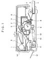
- Figure 1 shows a substantial cross section of a copy apparatus or an image formation apparatus to which the first embodiment of the invention is applied.
- 1 represents an original base made of glass or other transparent member.
- the original base 1 reciprocates in a-arrow direction to scan an original.
- a short-focus small-diameter image-formation element array 2 is arranged immediately under the original base 1.
- An original placed on the original base 1 is illuminated by a fluorescent lamp 3 or an illumination lamp.
- a reflecting mirror image of the original is slit-exposed on a photosensitive drum 4 rotating in b-arrow direction by the array 2.
- the charger 5 is a charger, and it uniformly charges the photosensitive drum 4 covered with a zinc oxide photosensitive layer or an organic semiconducting photosensitive layer.
- the drum 4 charged uniformly by the charger 5 is exposed by the array 2 to form an electrostatic latent image.
- the electrostatic latent image is made visible by a developing unit 6 using powdered toner which is softened and fused with heat.
- a sheet P stored in a cassette S is fed onto the drum by a pair of transportation rollers 8 which are compressed vertically and rotated in a certain time after a feed roller 7 to synchronize with the formation of an image on the photosensitive drum 4. Then, a transfer discharger 9 transfers a toner image formed on the photosensitive drum 4 onto the sheet P.
- a well-known separation means separates the sheet P from the drum 4.
- the sheet P is led to a heat fusing unit 11 by a transportation guide 10, heated and fused, and finally discharged onto a tray 12. After the toner image is transferred, the residual toner on the drum 4 is removed by a cleaner 13.
- An image formation means described in this embodiment forms an image on a recording material according to image information light obtained by illuminating an original. Specifically, it includes a process means in the vicinity of a drum 4 and a heat fusing unit which heats and fuses an image onto the recording material.
- Single fan 14 is located above the fusing unit 11, and cools a fluorescent lamp 3 and the fusing unit 11, and discharges ozone generated from a charger 5 out of the apparatus. Thus, the fan hampers the abnormal temperature rise of the fluorescent lamp 3 and prevents the fusing unit 11 from raising the temperature inside of the apparatus abnormally.
- FIG. 2 is a block diagram for explaining electric control around a lighting unit shown in Figure 1.
- 101 is a controlling circuit equipped with microcomputers.
- the input terminal IN is connected to a light amount sensor 102 which detects the light intensity of fluorescent lamp 3.
- the output terminals OUT 1 and OUT 2 are connected to a fan 14 and a fluorescent lamp driver 103 respectiyely.
- Terminal OUT 1 controls rotation of the fan 14 and terminal OUT 2 controls operation of fluorescent lamp 3 including preheating of the lamp and its intensity.
- Other input and output signals (not illustrated) are transferred to activate the copy operation of a copy apparatus of this embodiment.
- the cotrolling circuit 101 incorporates ROM and RAM in which the copy operation sequence program for the copy apparatus and other programs are written.
- FIG. 3 is a flowchart showing the fluorescent lamp lighting sequence and fan drive control sequence.
- the flowchart of Figure 3 represents a subroutine called at the start of a copy operation which is activated with the COPY switch turned ON.
- a filament or a well-known means for lighting a fluorescent lamp is energized to start a preheating operation.
- a fusing unit which is actuated with the COPY switch turned ON boosts the temperature inside of the apparatus.
- a fan is driven.
- the system waits until the preheating of the fluorescent lamp completes (step 2).
- control is passed to the fluorescent lamp so that the fluorescent lamp will be energized to light (step 3).
- step 4 the drive of the fan is inhibited (step 4). Then, the light intensity of the fluorescent lamp is detected by a light amount sensor 102. When the detected value reaches the preset value, the fan is driven again. After that, control is returned to a copy operation program.
- Figure 4 shows the rise in intensity of light emitted by the fluorescent lamp.
- A indicates the rise in intensity of a fluorescent lamp in a prior embodiment in which cooling by the fan is initiated by switching on a copying operation.
- a fan is stopped prior to the lamp reaching its required intensity. In this state, it is not possible to exhaust ozone generated from a charger or prevent a heat fusing unit from raising the temperature inside of an apparatus. If the operation of the fan is not so excessive as to cool the lamp too much, the fan may not be,stopped completely. When the fan driving force is maintained at a relatively low value until the intensity of the lamp has reached a given value, the same benefits as those provided by the aforesaid embodiment are made available.
- a single fan is used to cool a light source and a heat fusing unit, and exhaust ozone generated from a charging means.
- a cooling means for exclusive use of cooling the light source may be employed.
- the cooling means only may be controlled either to stop or to be driven at a lower speed. During this period, the cooling effect of the fan does not extend to the fusing unit. The fan may be stopped at the start of preheating or when a filament is energized.
- the intensity of the fluorescent lamp is detected to control the drive of the cooling fan.
- a temperature measuring means for measuring the temperature of the fluorescent lamp is also provided. Based on the measured temperature, it is determined whether to stop the fan or not.
- Figure 5 is a block diagram of this embodiment.
- a thermistor 104 for measuring the bulb surface temperature of a fluorescent lamp is attached to the fluorescent lamp.
- the thermistor 104 is connected to IN2 of a controlling circuit 101. Otherwise the configuration is identical to that of the first embodiment.
- FIG. 6 is a flowchart showing the operations of this embodiment, which represents a subroutine called at the start of a copy operation of a copy apparatus.
- a preheating operation is started to light a fluorescent lamp.
- the fan is driven to minimize a temperature rise inside of the apparatus derived from the heat of a fusing unit.
- the system waits until the preheating of the fluorescent lamp completes (step 2) then, the fluorescent lamp is energized to light (step 3).
- step 4 passes to step 4. If the temperature of the fluorescent lamp is lower than a preset value, for example 30°, control passes to a step 5 to stop the fan. If the temperature exceeds 30°, control advances to a step 6.
- step 6 it is verified that the light amount has reached a given value (step 6), and then the fan is driven (step 7).
- the fan is driven (step 7).
- the measuring means measures the temperature of the fluorescent lamp.
- the temperature in the vicinity of the fluorescent lamp or that inside of the copy apparatus may be measured to determine whether the drive of the fan is turned ON or OFF.
- the stop period of a fan is determined with the light amount or, additionally the temperature of a fluorescent lamp. In this arrangement, the stop period is determined under other image formation condition.
- the fan serves as a fanning means to exhaust ozone generated from a charger.
- a fluorescent lamp is energized with the COPY switch turned ON. After the drive of the fan is stopped, even if the light amount of the fluorescent lamp reaches a sufficient value, the drive of the fan remains stopped until charger charges a photosensitive drum or ozone is generated.
- a reflection plate (not illustrated) is used so that the light emitted from the fluorescent lamp will not illuminate the original but reach the photosensitive drum.
- the fluorescent lamp can emit the light to the photosensitive drum before reaching its operational intensity.
- the residual electric charges on the photosensitive drum can be eliminated to prevent the surface of the photosensitive drum from becoming electrically uneven.
- the light amount of the fluorescent lamp can be set to be a sufficient value by adjusting the duration from when the COPY switch is turned ON until the charger is turned ON.
- the optical sensor may be used to check if the light amount of a fluorescent lamp is increased to some extent, or reaches 90 % of a required amount. Then, a given time later, the drive of the fan may be turned ON with the charger turned ON. Thereby, the influence of ozone can be eliminated and the reliability in the light amount of a fluorescent lamp can be upgraded.
- the aforesaid embodiments relate to analog copy machines.
- the invention is also applicable to a digital copy machine in which a reading unit and a recording unit are set apart, as far as the machine comprises a fanning means which can cool a light source, and perform air exhaust and cooling under other image formation condition.
Landscapes
- Physics & Mathematics (AREA)
- General Physics & Mathematics (AREA)
- Life Sciences & Earth Sciences (AREA)
- Engineering & Computer Science (AREA)
- Atmospheric Sciences (AREA)
- Biodiversity & Conservation Biology (AREA)
- Ecology (AREA)
- Environmental & Geological Engineering (AREA)
- Environmental Sciences (AREA)
- Control Or Security For Electrophotography (AREA)
- Light Sources And Details Of Projection-Printing Devices (AREA)
- Exposure Or Original Feeding In Electrophotography (AREA)
Applications Claiming Priority (2)
| Application Number | Priority Date | Filing Date | Title |
|---|---|---|---|
| JP36715/90 | 1990-02-17 | ||
| JP2036715A JP2714205B2 (ja) | 1990-02-17 | 1990-02-17 | 複写装置 |
Publications (2)
| Publication Number | Publication Date |
|---|---|
| EP0443784A1 EP0443784A1 (en) | 1991-08-28 |
| EP0443784B1 true EP0443784B1 (en) | 1995-07-12 |
Family
ID=12477449
Family Applications (1)
| Application Number | Title | Priority Date | Filing Date |
|---|---|---|---|
| EP91301232A Expired - Lifetime EP0443784B1 (en) | 1990-02-17 | 1991-02-15 | Lighting unit, and image formation apparatus with it |
Country Status (4)
| Country | Link |
|---|---|
| US (1) | US5508782A (ja) |
| EP (1) | EP0443784B1 (ja) |
| JP (1) | JP2714205B2 (ja) |
| DE (1) | DE69111092T2 (ja) |
Cited By (1)
| Publication number | Priority date | Publication date | Assignee | Title |
|---|---|---|---|---|
| CN101852976A (zh) * | 2004-05-11 | 2010-10-06 | 精工爱普生株式会社 | 投射设备 |
Families Citing this family (12)
| Publication number | Priority date | Publication date | Assignee | Title |
|---|---|---|---|---|
| JP3494684B2 (ja) * | 1993-01-07 | 2004-02-09 | 富士写真フイルム株式会社 | ランプ温度制御装置及びこれを用いたカラー感熱プリンタ |
| JP3136240B2 (ja) * | 1994-06-22 | 2001-02-19 | シャープ株式会社 | 画像形成装置 |
| JP3393937B2 (ja) * | 1994-10-18 | 2003-04-07 | 富士写真フイルム株式会社 | ランプ温度制御装置及びこれを用いたカラー感熱プリンタ |
| KR0149778B1 (ko) * | 1995-08-18 | 1998-12-01 | 김광호 | 화상형성장치의 오존방출팬 구동 제어방법 |
| EP1057197A4 (en) * | 1998-02-19 | 2002-04-17 | Universal Avionics Sys Corp | BACKGROUND LAMP MODULE COOLING METHOD FOR LIQUID CRYSTAL DISPLAY |
| US6621239B1 (en) * | 2000-03-14 | 2003-09-16 | Richard S. Belliveau | Method and apparatus for controlling the temperature of a multi-parameter light |
| US7015470B2 (en) * | 2003-07-15 | 2006-03-21 | Lear Corporation | Active night vision cooling system |
| US7233493B2 (en) * | 2004-08-10 | 2007-06-19 | E. I. Du Pont De Nemours And Company | Electronic device having a temperature control system including a ductwork assembly |
| US7286347B2 (en) * | 2004-08-10 | 2007-10-23 | Dupont Displays | Electronic device having a temperature control system |
| US7294979B2 (en) * | 2005-05-27 | 2007-11-13 | Hewlett-Packard Development Company, L.P. | Light source module with temperature sensor |
| CN113022117B (zh) * | 2021-03-03 | 2022-11-15 | 山东朝泰实业有限公司 | 基于环保水墨打底的冷光源led纹路胶辊转印印刷系统 |
| CN113590168B (zh) * | 2021-07-29 | 2024-03-01 | 百度在线网络技术(北京)有限公司 | 嵌入式设备升级方法、装置、设备、介质及程序产品 |
Family Cites Families (19)
| Publication number | Priority date | Publication date | Assignee | Title |
|---|---|---|---|---|
| FR615969A (fr) * | 1925-10-03 | 1927-01-20 | Parisienne De Carrosserie Auto | Armature de capote pour véhicules |
| US3330180A (en) * | 1964-10-14 | 1967-07-11 | Xerox Corp | Illumination control system |
| JPS552212A (en) * | 1978-06-19 | 1980-01-09 | Toshiba Corp | Copying apparatus |
| JPS56123564A (en) * | 1980-03-05 | 1981-09-28 | Fuji Xerox Co Ltd | Original illumination device for electronic copy machine |
| JPS5878176A (ja) * | 1981-11-04 | 1983-05-11 | Seiko Epson Corp | 印写装置 |
| JPS58153955A (ja) * | 1982-03-09 | 1983-09-13 | Sharp Corp | 複写機におけるオゾン除去装置 |
| US4518895A (en) * | 1983-03-25 | 1985-05-21 | Xerox Corporation | Mechanism and method for controlling the temperature and output of a fluorescent lamp |
| US4533853A (en) * | 1983-03-25 | 1985-08-06 | Xerox Corporation | Mechanism and method for controlling the temperature and output of a fluorescent lamp |
| US4533854A (en) * | 1983-03-25 | 1985-08-06 | Xerox Corporation | Mechanism and method for controlling the temperature and output of a fluorescent lamp |
| JPS61188557A (ja) * | 1985-02-18 | 1986-08-22 | Sharp Corp | 帯電器のオゾンガス排出機構 |
| US4720727A (en) * | 1985-03-04 | 1988-01-19 | Canon Kabushiki Kaisha | Image forming apparatus |
| JP2607523B2 (ja) * | 1987-05-30 | 1997-05-07 | 株式会社東芝 | 画像形成装置 |
| EP0295491B1 (en) * | 1987-06-04 | 1993-08-18 | Dainippon Screen Mfg. Co., Ltd. | Apparatus for and method of stabilizing the quantity of light of fluorescent lamp |
| US4887122A (en) * | 1987-11-04 | 1989-12-12 | Minolta Camera Kabushiki Kaisha | Copying machine |
| JP2578841B2 (ja) * | 1987-11-12 | 1997-02-05 | キヤノン株式会社 | 画像形成装置 |
| US4952986A (en) * | 1988-03-29 | 1990-08-28 | Sharp Kabushiki Kaisha | Copying apparatus |
| JPH0218857A (ja) * | 1988-07-04 | 1990-01-23 | Japan Aviation Electron Ind Ltd | 蛍光ランプ装置 |
| JP2824285B2 (ja) * | 1989-07-21 | 1998-11-11 | 株式会社リコー | 照明装置の始動制御装置 |
| US5150154A (en) * | 1989-08-22 | 1992-09-22 | Brother Kogyo Kabushiki Kaisha | Apparatus for forming images discharge lamp and current, tone and temperature control means |
-
1990
- 1990-02-17 JP JP2036715A patent/JP2714205B2/ja not_active Expired - Fee Related
-
1991
- 1991-02-15 EP EP91301232A patent/EP0443784B1/en not_active Expired - Lifetime
- 1991-02-15 DE DE69111092T patent/DE69111092T2/de not_active Expired - Fee Related
-
1994
- 1994-11-08 US US08/336,759 patent/US5508782A/en not_active Expired - Fee Related
Non-Patent Citations (2)
| Title |
|---|
| PATENT ABSTRACTS OF JAPAN, vol. 11, no. 12 (P-535)(2459), 13th January 1987;& JP-A-61188557 * |
| PATENT ABSTRACTS OF JAPAN, vol. 7, no. 274 (P-241)(1419), 7th December 1983;& JP-A-58153955 * |
Cited By (2)
| Publication number | Priority date | Publication date | Assignee | Title |
|---|---|---|---|---|
| CN101852976A (zh) * | 2004-05-11 | 2010-10-06 | 精工爱普生株式会社 | 投射设备 |
| CN101852976B (zh) * | 2004-05-11 | 2013-01-09 | 精工爱普生株式会社 | 投射设备 |
Also Published As
| Publication number | Publication date |
|---|---|
| DE69111092D1 (de) | 1995-08-17 |
| EP0443784A1 (en) | 1991-08-28 |
| US5508782A (en) | 1996-04-16 |
| JPH03239272A (ja) | 1991-10-24 |
| JP2714205B2 (ja) | 1998-02-16 |
| DE69111092T2 (de) | 1995-11-23 |
Similar Documents
| Publication | Publication Date | Title |
|---|---|---|
| EP0443784B1 (en) | Lighting unit, and image formation apparatus with it | |
| US5138379A (en) | Image forming apparatus having temperature and humidity detecting means | |
| US4994852A (en) | Image forming apparatus having a malfunction detection device and power shutdown therefor | |
| US4998121A (en) | Image forming apparatus | |
| KR890004403B1 (ko) | 복사기의 제어방법 | |
| US5032874A (en) | Image forming apparatus having a system for preventing overheating of the heat rollers | |
| US4349269A (en) | Manual paper feed inhibiting device in electrographic copying machine | |
| US4497568A (en) | Image formation apparatus | |
| US4887122A (en) | Copying machine | |
| EP0443806B1 (en) | Image forming apparatus having fixing means error detector | |
| US5300981A (en) | Electrophotographic printing apparatus with fire prevention | |
| US4391508A (en) | Counter and timing mechanism for copying apparatus | |
| JPH07181830A (ja) | 画像形成装置 | |
| JP2000259034A (ja) | 画像形成装置 | |
| US5095329A (en) | Copying machine | |
| JP3315495B2 (ja) | 画像形成装置 | |
| JPH07253733A (ja) | 画像形成装置 | |
| JP3062053B2 (ja) | 画像形成装置 | |
| US4999666A (en) | Image forming apparatus having drive control unit | |
| JP3262611B2 (ja) | 画像形成装置 | |
| JP2629039B2 (ja) | 熱定着装置 | |
| JPH11161097A (ja) | 定着装置、温度制御手段及びこれらを備える画像形成装置 | |
| JPH0816029A (ja) | 画像形成装置 | |
| JPH0685101B2 (ja) | 画像形成装置 | |
| JPH01297667A (ja) | 画像形成装置 |
Legal Events
| Date | Code | Title | Description |
|---|---|---|---|
| PUAI | Public reference made under article 153(3) epc to a published international application that has entered the european phase |
Free format text: ORIGINAL CODE: 0009012 |
|
| AK | Designated contracting states |
Kind code of ref document: A1 Designated state(s): DE FR GB IT |
|
| 17P | Request for examination filed |
Effective date: 19920113 |
|
| 17Q | First examination report despatched |
Effective date: 19930426 |
|
| GRAA | (expected) grant |
Free format text: ORIGINAL CODE: 0009210 |
|
| AK | Designated contracting states |
Kind code of ref document: B1 Designated state(s): DE FR GB IT |
|
| REF | Corresponds to: |
Ref document number: 69111092 Country of ref document: DE Date of ref document: 19950817 |
|
| ITF | It: translation for a ep patent filed | ||
| ET | Fr: translation filed | ||
| PLBE | No opposition filed within time limit |
Free format text: ORIGINAL CODE: 0009261 |
|
| STAA | Information on the status of an ep patent application or granted ep patent |
Free format text: STATUS: NO OPPOSITION FILED WITHIN TIME LIMIT |
|
| 26N | No opposition filed | ||
| REG | Reference to a national code |
Ref country code: GB Ref legal event code: IF02 |
|
| PGFP | Annual fee paid to national office [announced via postgrant information from national office to epo] |
Ref country code: GB Payment date: 20030203 Year of fee payment: 13 |
|
| PGFP | Annual fee paid to national office [announced via postgrant information from national office to epo] |
Ref country code: FR Payment date: 20030220 Year of fee payment: 13 |
|
| PGFP | Annual fee paid to national office [announced via postgrant information from national office to epo] |
Ref country code: DE Payment date: 20030221 Year of fee payment: 13 |
|
| PG25 | Lapsed in a contracting state [announced via postgrant information from national office to epo] |
Ref country code: GB Free format text: LAPSE BECAUSE OF NON-PAYMENT OF DUE FEES Effective date: 20040215 |
|
| PG25 | Lapsed in a contracting state [announced via postgrant information from national office to epo] |
Ref country code: DE Free format text: LAPSE BECAUSE OF NON-PAYMENT OF DUE FEES Effective date: 20040901 |
|
| GBPC | Gb: european patent ceased through non-payment of renewal fee |
Effective date: 20040215 |
|
| PG25 | Lapsed in a contracting state [announced via postgrant information from national office to epo] |
Ref country code: FR Free format text: LAPSE BECAUSE OF NON-PAYMENT OF DUE FEES Effective date: 20041029 |
|
| REG | Reference to a national code |
Ref country code: FR Ref legal event code: ST |
|
| PG25 | Lapsed in a contracting state [announced via postgrant information from national office to epo] |
Ref country code: IT Free format text: LAPSE BECAUSE OF NON-PAYMENT OF DUE FEES Effective date: 20050215 |