EP0443817A1 - Pointeur à lumiÀ¨re focalisée pour affichage tridimensionnel - Google Patents
Pointeur à lumiÀ¨re focalisée pour affichage tridimensionnel Download PDFInfo
- Publication number
- EP0443817A1 EP0443817A1 EP91301316A EP91301316A EP0443817A1 EP 0443817 A1 EP0443817 A1 EP 0443817A1 EP 91301316 A EP91301316 A EP 91301316A EP 91301316 A EP91301316 A EP 91301316A EP 0443817 A1 EP0443817 A1 EP 0443817A1
- Authority
- EP
- European Patent Office
- Prior art keywords
- light receiving
- receiving means
- pointer
- rotating light
- set forth
- Prior art date
- Legal status (The legal status is an assumption and is not a legal conclusion. Google has not performed a legal analysis and makes no representation as to the accuracy of the status listed.)
- Granted
Links
Images


Classifications
-
- G—PHYSICS
- G02—OPTICS
- G02B—OPTICAL ELEMENTS, SYSTEMS OR APPARATUS
- G02B27/00—Optical systems or apparatus not provided for by any of the groups G02B1/00 - G02B26/00, G02B30/00
- G02B27/18—Optical systems or apparatus not provided for by any of the groups G02B1/00 - G02B26/00, G02B30/00 for optical projection, e.g. combination of mirror and condenser and objective
- G02B27/20—Optical systems or apparatus not provided for by any of the groups G02B1/00 - G02B26/00, G02B30/00 for optical projection, e.g. combination of mirror and condenser and objective for imaging minute objects, e.g. light-pointer
-
- G—PHYSICS
- G02—OPTICS
- G02B—OPTICAL ELEMENTS, SYSTEMS OR APPARATUS
- G02B30/00—Optical systems or apparatus for producing three-dimensional [3D] effects, e.g. stereoscopic images
- G02B30/50—Optical systems or apparatus for producing three-dimensional [3D] effects, e.g. stereoscopic images the image being built up from image elements distributed over a three-dimensional [3D] volume, e.g. voxels
- G02B30/54—Optical systems or apparatus for producing three-dimensional [3D] effects, e.g. stereoscopic images the image being built up from image elements distributed over a three-dimensional [3D] volume, e.g. voxels the three-dimensional [3D] volume being generated by moving a two-dimensional [2D] surface, e.g. by vibrating or rotating the 2D surface
-
- G—PHYSICS
- G02—OPTICS
- G02B—OPTICAL ELEMENTS, SYSTEMS OR APPARATUS
- G02B5/00—Optical elements other than lenses
- G02B5/32—Holograms used as optical elements
-
- H—ELECTRICITY
- H04—ELECTRIC COMMUNICATION TECHNIQUE
- H04N—PICTORIAL COMMUNICATION, e.g. TELEVISION
- H04N13/00—Stereoscopic video systems; Multi-view video systems; Details thereof
- H04N13/30—Image reproducers
- H04N13/363—Image reproducers using image projection screens
-
- H—ELECTRICITY
- H04—ELECTRIC COMMUNICATION TECHNIQUE
- H04N—PICTORIAL COMMUNICATION, e.g. TELEVISION
- H04N13/00—Stereoscopic video systems; Multi-view video systems; Details thereof
- H04N13/30—Image reproducers
- H04N13/388—Volumetric displays, i.e. systems where the image is built up from picture elements distributed through a volume
- H04N13/393—Volumetric displays, i.e. systems where the image is built up from picture elements distributed through a volume the volume being generated by a moving, e.g. vibrating or rotating, surface
-
- H—ELECTRICITY
- H04—ELECTRIC COMMUNICATION TECHNIQUE
- H04N—PICTORIAL COMMUNICATION, e.g. TELEVISION
- H04N13/00—Stereoscopic video systems; Multi-view video systems; Details thereof
- H04N13/10—Processing, recording or transmission of stereoscopic or multi-view image signals
-
- H—ELECTRICITY
- H04—ELECTRIC COMMUNICATION TECHNIQUE
- H04N—PICTORIAL COMMUNICATION, e.g. TELEVISION
- H04N13/00—Stereoscopic video systems; Multi-view video systems; Details thereof
- H04N13/30—Image reproducers
- H04N13/398—Synchronisation thereof; Control thereof
Definitions
- This invention relates to a pointer for a three dimensional display system and, more specifically, to a modulated focussed light source for locating a point in three dimensional space in a real time three dimensional display.
- a system which is superior to the systems denoted hereinabove and other known systems is disclosed in the copending application of Felix Garcia, Jr., Serial No. 07/390,473, filed August 3, 1989, the disclosure of which is incorporated herein by reference.
- a three dimensional display system which is not substantially affected by G forces and wherein the size of the displayed image and screen is determined by the size of a disk and motor.
- the system can be used, for example, in business and industrial uses, such as solid animation, radar display, molecular research, resonant frequency and harmonics display, military, computer graphics and the like.
- the system includes a disk-like screen connected to the end of a motor shaft.
- the disk is attached to the shaft of a motor preferably at a 45 degree angle to the shaft, though this angle can be varied to provide a larger or smaller height or z-axis dimension so that, as the disk rotates, a displacement of any given point thereon along the z axis takes place.
- the image is formed on the screen by projecting a light beam, such as from a laser, through a modulator and toward a scanner which produces an x-y scan of the beam on a screen, the screen herein being the disk discussed hereinabove.
- the disk can be translucent, such as lucite, so that images can be projected thereon onto the front and/or rear surfaces thereof.
- the modulation or strobing of the scan is synchronized with the rotating disk by control of the motor speed and/or the strobe rate so that a three dimensional pattern appears on the screen. It can be seen that any point on the x-y scan from the scanner which impinges upon the screen will move along a z-axis direction since the screen or disk at that point produces such z-axis movement. This movement of the displayed image provides the three dimensional effect.
- the adjustment of the angle between the disk surface and the x-y plane of the scanned x-y image will determine the z dimension or height of the three dimensional image, the disk angle being adjustable on-line, if so desired.
- the disk is preferably a planar opaque screen for receiving a scanned image thereon on one surface thereof.
- the screen can, however, take different forms such as, for example, being translucent, such as lucite, and thereby being capable of receiving a scanned image thereon on both major surfaces or transmitting images received on one surface thereof to the opposing surface for viewing or other operation.
- the lucite disk can be in the form of a pair of angularly truncated cylinders which fit together at the angularly truncated surfaces to form a new cylinder wherein the surfaces at which truncation takes place are translucent.
- the screen can take on shapes other than planar, it merely being necessary that at least some portion thereof move in the z-direction during rotation thereof while projection of the x-y image thereon takes place to provide the three dimensional image.
- the disk can be placed in a gas filled CRT with the image impinging thereon being the scanned beam of the tube. Phosphors can be disposed on the disk which, when excited, form the three dimensional image.
- the screen can be planar and disposed normal to the projected x-y image.
- a focussed light source which can selectively locate and illuminate any predetermined point or points in a display of the above described type from a location outside of the display.
- a pointer system which includes a modulated light source, preferably a modulated laser, which can be positioned relative to the display, such as by hand, to strike a predetermined point or points therein in three dimensions.
- the light beam from the light source is modulated on and off in synchronism with the rotation of the display so that the light from the light source alway impinges upon the predetermined point or points on the display when the predetermined point or points are at a predetermined location in their field of rotation.
- a pointer the light from which can strike any point in the 3-D display volume since any point on the disk can have light from the source impinge thereon at any point in the rotary path of that point.
- the disk in order to encode the location of the point in space on which the point or points of light are impinging, the disk is made transparent or translucent so that the light impinging thereon can pass therethrough.
- a plurality of light pipes are disposed on the side of the disk opposite from the display and rotate with the disk. Light impinging on the disk passes therethrough and through the light pipes to a sensor composed of plural sensing elements, the sensing elements determining the x-y location of the light impinging thereon.
- an encoder provides an indication of the instantaneous rotary position of the disk from which the x-location can be determined.
- the location of the point in space selected by the pointer is determined by the point on the disk on which the light impinges, this being determined by the particular light pipe illuminated by the pointer, and the position of the disk in its trajectory, this being determined by the encoder on the shaft driving the disk.
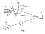
- FIGURE 1 there is shown a schematic diagram of a system in accordance with the present invention.
- the system includes a laser 7 which projects a light beam through a modulator 4 onto an x-y scanner 5.
- the modulator 4 is externally controlled in predetermined manner (not shown) to control the intensity of the laser light beam 3 passing therethrough to the x-y scanner 5. It is understood that the light intensity can be controlled so that no light passes through the modulator when so desired, either by use of a light valve or by deflection of all or a portion of the light beam from the light beam path 3 as shown.
- the x-y scanner 5 whose scanning rate is externally controllable in standard manner (not shown), scans the light beam 3 from the modulator along an x-y plane and projects this x-y image 6 onto a screen 1, preferably in the form of a disk as will be explained hereinbelow.
- the screen 1 is rotated by a motor 8 via a shaft 2 to which the screen is secured, the motor speed being controllable by means of a standard controller (not shown).
- the motor speed is preferably synchronized with the scanning rate of the scanner 5.
- the disk 1 will preferably have a rotational speed in excess of eighteen revolutions per second to avoid flickering and the like.
- FIGURE 2 of the above noted Garcia, Jr. application One typical circuit for providing such synchronization is shown in FIGURE 2 of the above noted Garcia, Jr. application so that the same spot on the disk is always present to receive a particular part of the x-y scan projected thereon.
- the screen 1 can be a rigid standard type movie screen if it is to be viewed from only one side thereof, as for the system described herein thus far.
- the screen angle is preferably 45 degrees with respect to the image received from the scanner, however, this angle can be altered up to about but less than 45 degrees in either direction, the effect of such angle alteration being to vary the height or z-dimension of the displayed image with continued change in such angle.
- the screen angle can be made variable on line, if so desired, by a structure (not shown) of known type which rotates the screen on the shaft 2.
- the screen 1 need not be planar but can be undulating or take many other shapes.
- a pointer 12 which provides a narrow beam light source and is shown as a laser 10 and a modulator 11, is preferrably hand held and is provided to transmit a narrow beam of light 14 onto the disk or screen 1.
- the light beam 14 is modulated on and off by the modulator 11 which permits the light beam to be on for only a small instant during each revolution of the shaft 2.
- the disk 1 rotates in synchronism with the modulator 11 and shaft encoder 9 for the x and y inputs.
- the z input is + or - out of synchronization for random selection of a spot on the disk 1.
- the out of synchronism z input which determines the height of the image enters the modulator 11 via controller 17 located on the pointer 10.
- a light beam from the laser 7 is modulated by the externally controllable modulator 4 to provide a modulated beam 3 which strikes the x-y scanner 5, the latter having an externally controllable scanning rate.
- the scanner 5 scans the light beam in an x-y plane onto the rotating disk or screen 1, the speed of rotation of the screen 1 being synchronized to the scanning rate of the scanner 5.
- any point of light in the x-y plane impinging upon the screen 1 will display a harmonic type motion in the z-plane due to the similar movement of points on the screen.
- the pointer 10 composed of laser 10 and modulator 11 is turned on and aimed so that the light beam 14 therefrom will impinge upon the selected point in space.
- the desired point in space will rest on the surface of the disk at least once per disk revolution.
- the modulator 11 momentarily modulates or turns on the beam from the laser 10 in known manner as explained hereinabove so that light from the laser impinges on the disk 1 to provide a point illuminating source.
- the light beam 14 can be greater than a point source, such as, for example, in the shape of an arrow, with appropriate synchronization of the modulator 11 to permit an arrow to appear at the predetermined location in space due to the impingement of light from many point sources in the shape of an arrow or from a single source in the shape of an arrow on the disk 1.
- a point source such as, for example, in the shape of an arrow
- FIGURES 3 and 4 A typical control system for controlling the synchronization of the modulator 11 relative to the rotational speed of the disk 1 is set forth in FIGURES 3 and 4 wherein it can be seen in FIGURE 3 that a computer 21 is under control of synchronizing user interface software 23 which provides synchronization signals and data signals to the computer.
- the computer 21, in response to the data and synchronizing signals provides the necessary information to each of the x-y sensor 5, the shaft encoder 9, the modulator 11 and the z input device 17 via the modulator to provide control thereof.
- FIGURE 2 there is shown a second embodiment of the invention wherein the disk 1 of FIGURE 1 is rendered transparent or translucent and capable of transmitting light therethrough and whereby the specific location of a point on the disk 1 at which the light impinges can be determined.
- a shaft encoder 9 of standard design which is associated with the shaft 2 to provide an indication of the instantaneous angular position of the shaft and the disk 1 rotated therewith.
- fiber optics or a holographic plate 13 which direct the light passing through the disk 1 to a stationary sensor 15.
- the fiber optics or holographic plate 13 rotate with the shaft 2 to project light therethrough onto the stationary sensor 15 which comprises a plurality of light responsive elements.
- the light responsive elements of the sensor 15 are preaddressed as to their location in known manner so that the particular element or elements thereof onto which the light from the pointer enters provide the x-y position of the light beam.
- the z-position is determined by the reading of the encoder 9 in standard manner, the z-position being known from the rotational position of the shaft 2.
- FIGURE 5 there is shown a top view of a typical hologram as well as a side view thereof in a spinning configuration as shown in FIGURE 2 with the disk 1 removed.
- an optical pointer which can provide a point indication or other shape in three dimensional space in conjunction with the display of the above noted application as well as locate the three dimensional position of the point in space.
Landscapes
- Physics & Mathematics (AREA)
- General Physics & Mathematics (AREA)
- Optics & Photonics (AREA)
- Engineering & Computer Science (AREA)
- Multimedia (AREA)
- Signal Processing (AREA)
- Diffracting Gratings Or Hologram Optical Elements (AREA)
- Digital Computer Display Output (AREA)
- Mechanical Optical Scanning Systems (AREA)
- Devices For Indicating Variable Information By Combining Individual Elements (AREA)
- Optical Transform (AREA)
Applications Claiming Priority (2)
| Application Number | Priority Date | Filing Date | Title |
|---|---|---|---|
| US482471 | 1990-02-21 | ||
| US07/482,471 US5024494A (en) | 1987-10-07 | 1990-02-21 | Focussed light source pointer for three dimensional display |
Publications (2)
| Publication Number | Publication Date |
|---|---|
| EP0443817A1 true EP0443817A1 (fr) | 1991-08-28 |
| EP0443817B1 EP0443817B1 (fr) | 1995-07-05 |
Family
ID=23916217
Family Applications (1)
| Application Number | Title | Priority Date | Filing Date |
|---|---|---|---|
| EP91301316A Expired - Lifetime EP0443817B1 (fr) | 1990-02-21 | 1991-02-20 | Pointeur à lumière focalisée pour affichage tridimensionnel |
Country Status (4)
| Country | Link |
|---|---|
| US (1) | US5024494A (fr) |
| EP (1) | EP0443817B1 (fr) |
| JP (1) | JP2791225B2 (fr) |
| DE (1) | DE69110921T2 (fr) |
Cited By (1)
| Publication number | Priority date | Publication date | Assignee | Title |
|---|---|---|---|---|
| EP0704721A3 (fr) * | 1994-09-27 | 1997-12-17 | AT&T Corp. | Méthode et appareil pour produire et afficher des images holographiques en utilisant un ponteur à laser |
Families Citing this family (71)
| Publication number | Priority date | Publication date | Assignee | Title |
|---|---|---|---|---|
| US6219015B1 (en) | 1992-04-28 | 2001-04-17 | The Board Of Directors Of The Leland Stanford, Junior University | Method and apparatus for using an array of grating light valves to produce multicolor optical images |
| US5418632A (en) * | 1994-01-21 | 1995-05-23 | Texas Instruments Incorporated | System and method for rotational scanner based volume display |
| US5854613A (en) * | 1994-03-16 | 1998-12-29 | The United Sates Of America As Represented By The Secretary Of The Navy | Laser based 3D volumetric display system |
| US6052100A (en) * | 1994-03-16 | 2000-04-18 | The United States Of America Represented By The Secertary Of The Navy | Computer controlled three-dimensional volumetric display |
| US5945966A (en) * | 1996-10-02 | 1999-08-31 | The United States Of America As Represented By The Secretary Of The Navy | Computer program for a three-dimensional volumetric display |
| US5841579A (en) | 1995-06-07 | 1998-11-24 | Silicon Light Machines | Flat diffraction grating light valve |
| WO1997035223A1 (fr) | 1996-03-15 | 1997-09-25 | Retinal Display Cayman Limited | Procede et appareil pour visualiser une image |
| TW306699U (en) * | 1996-06-14 | 1997-05-21 | Shr Jia Co Ltd | Visible light laser diode module |
| US5718496A (en) * | 1996-06-25 | 1998-02-17 | Digital Optics Corporation | Projection pointer |
| JPH1020765A (ja) * | 1996-07-04 | 1998-01-23 | Sekinosu Kk | レーザーポインター |
| US5982553A (en) | 1997-03-20 | 1999-11-09 | Silicon Light Machines | Display device incorporating one-dimensional grating light-valve array |
| US6088102A (en) | 1997-10-31 | 2000-07-11 | Silicon Light Machines | Display apparatus including grating light-valve array and interferometric optical system |
| US6271808B1 (en) | 1998-06-05 | 2001-08-07 | Silicon Light Machines | Stereo head mounted display using a single display device |
| US6130770A (en) | 1998-06-23 | 2000-10-10 | Silicon Light Machines | Electron gun activated grating light valve |
| US6101036A (en) | 1998-06-23 | 2000-08-08 | Silicon Light Machines | Embossed diffraction grating alone and in combination with changeable image display |
| US6215579B1 (en) | 1998-06-24 | 2001-04-10 | Silicon Light Machines | Method and apparatus for modulating an incident light beam for forming a two-dimensional image |
| US6079835A (en) * | 1998-07-14 | 2000-06-27 | Acropro, Inc. | Adjustable laser projector |
| US6872984B1 (en) | 1998-07-29 | 2005-03-29 | Silicon Light Machines Corporation | Method of sealing a hermetic lid to a semiconductor die at an angle |
| WO2000007066A1 (fr) | 1998-07-29 | 2000-02-10 | Digilens, Inc. | Systeme d'affichage plat en ligne utilisant un ou plusieurs elements optiques holographiques commutables |
| US6303986B1 (en) | 1998-07-29 | 2001-10-16 | Silicon Light Machines | Method of and apparatus for sealing an hermetic lid to a semiconductor die |
| AU6143199A (en) * | 1998-09-14 | 2000-04-03 | Digilens Inc. | Holographic illumination system and holographic projection system |
| US6339486B1 (en) | 1998-10-16 | 2002-01-15 | Digilens, Inc. | Holographic technique for illumination of image displays using ambient illumination |
| US6421109B1 (en) | 1998-10-16 | 2002-07-16 | Digilens, Inc. | Method and system for display resolution multiplication |
| US6678078B1 (en) | 1999-01-07 | 2004-01-13 | Digilens, Inc. | Optical filter employing holographic optical elements and image generating system incorporating the optical filter |
| US6507419B1 (en) | 1999-03-23 | 2003-01-14 | Digilens, Inc. | Illumination system using optical feedback |
| US6504629B1 (en) | 1999-03-23 | 2003-01-07 | Digilens, Inc. | Method and apparatus for illuminating a display |
| EP1055954A1 (fr) * | 1999-05-28 | 2000-11-29 | University of Liege | Dispositif optique pour système de projection |
| JP2000338599A (ja) | 1999-05-28 | 2000-12-08 | Univ De Liege | 投影表示システム用光学装置およびホログラフィックミラーの製造方法。 |
| WO2001011895A1 (fr) | 1999-08-04 | 2001-02-15 | Digilens, Inc. | Appareil de production d'une image tridimensionnelle |
| US6956878B1 (en) | 2000-02-07 | 2005-10-18 | Silicon Light Machines Corporation | Method and apparatus for reducing laser speckle using polarization averaging |
| US6424437B1 (en) | 2000-10-10 | 2002-07-23 | Digilens, Inc. | Projection display employing switchable holographic optical elements |
| US7177081B2 (en) | 2001-03-08 | 2007-02-13 | Silicon Light Machines Corporation | High contrast grating light valve type device |
| US6707591B2 (en) | 2001-04-10 | 2004-03-16 | Silicon Light Machines | Angled illumination for a single order light modulator based projection system |
| US6865346B1 (en) | 2001-06-05 | 2005-03-08 | Silicon Light Machines Corporation | Fiber optic transceiver |
| US6747781B2 (en) | 2001-06-25 | 2004-06-08 | Silicon Light Machines, Inc. | Method, apparatus, and diffuser for reducing laser speckle |
| US6782205B2 (en) | 2001-06-25 | 2004-08-24 | Silicon Light Machines | Method and apparatus for dynamic equalization in wavelength division multiplexing |
| US6829092B2 (en) | 2001-08-15 | 2004-12-07 | Silicon Light Machines, Inc. | Blazed grating light valve |
| US6930364B2 (en) | 2001-09-13 | 2005-08-16 | Silicon Light Machines Corporation | Microelectronic mechanical system and methods |
| US6744502B2 (en) * | 2001-09-28 | 2004-06-01 | Pe Corporation (Ny) | Shaped illumination geometry and intensity using a diffractive optical element |
| US6956995B1 (en) | 2001-11-09 | 2005-10-18 | Silicon Light Machines Corporation | Optical communication arrangement |
| US6800238B1 (en) | 2002-01-15 | 2004-10-05 | Silicon Light Machines, Inc. | Method for domain patterning in low coercive field ferroelectrics |
| US6728023B1 (en) | 2002-05-28 | 2004-04-27 | Silicon Light Machines | Optical device arrays with optimized image resolution |
| US6767751B2 (en) | 2002-05-28 | 2004-07-27 | Silicon Light Machines, Inc. | Integrated driver process flow |
| US7054515B1 (en) | 2002-05-30 | 2006-05-30 | Silicon Light Machines Corporation | Diffractive light modulator-based dynamic equalizer with integrated spectral monitor |
| US6822797B1 (en) | 2002-05-31 | 2004-11-23 | Silicon Light Machines, Inc. | Light modulator structure for producing high-contrast operation using zero-order light |
| US6839168B2 (en) * | 2002-06-21 | 2005-01-04 | Seiko Epson Corporation | Screen |
| US6829258B1 (en) | 2002-06-26 | 2004-12-07 | Silicon Light Machines, Inc. | Rapidly tunable external cavity laser |
| US6908201B2 (en) | 2002-06-28 | 2005-06-21 | Silicon Light Machines Corporation | Micro-support structures |
| US6714337B1 (en) | 2002-06-28 | 2004-03-30 | Silicon Light Machines | Method and device for modulating a light beam and having an improved gamma response |
| US6813059B2 (en) | 2002-06-28 | 2004-11-02 | Silicon Light Machines, Inc. | Reduced formation of asperities in contact micro-structures |
| US7057795B2 (en) | 2002-08-20 | 2006-06-06 | Silicon Light Machines Corporation | Micro-structures with individually addressable ribbon pairs |
| US6801354B1 (en) | 2002-08-20 | 2004-10-05 | Silicon Light Machines, Inc. | 2-D diffraction grating for substantially eliminating polarization dependent losses |
| US6712480B1 (en) | 2002-09-27 | 2004-03-30 | Silicon Light Machines | Controlled curvature of stressed micro-structures |
| US6928207B1 (en) | 2002-12-12 | 2005-08-09 | Silicon Light Machines Corporation | Apparatus for selectively blocking WDM channels |
| US6987600B1 (en) | 2002-12-17 | 2006-01-17 | Silicon Light Machines Corporation | Arbitrary phase profile for better equalization in dynamic gain equalizer |
| US7057819B1 (en) | 2002-12-17 | 2006-06-06 | Silicon Light Machines Corporation | High contrast tilting ribbon blazed grating |
| US6934070B1 (en) | 2002-12-18 | 2005-08-23 | Silicon Light Machines Corporation | Chirped optical MEM device |
| US6927891B1 (en) | 2002-12-23 | 2005-08-09 | Silicon Light Machines Corporation | Tilt-able grating plane for improved crosstalk in 1×N blaze switches |
| US7068372B1 (en) | 2003-01-28 | 2006-06-27 | Silicon Light Machines Corporation | MEMS interferometer-based reconfigurable optical add-and-drop multiplexor |
| US7286764B1 (en) | 2003-02-03 | 2007-10-23 | Silicon Light Machines Corporation | Reconfigurable modulator-based optical add-and-drop multiplexer |
| US6947613B1 (en) | 2003-02-11 | 2005-09-20 | Silicon Light Machines Corporation | Wavelength selective switch and equalizer |
| US6922272B1 (en) | 2003-02-14 | 2005-07-26 | Silicon Light Machines Corporation | Method and apparatus for leveling thermal stress variations in multi-layer MEMS devices |
| US7391973B1 (en) | 2003-02-28 | 2008-06-24 | Silicon Light Machines Corporation | Two-stage gain equalizer |
| US6806997B1 (en) | 2003-02-28 | 2004-10-19 | Silicon Light Machines, Inc. | Patterned diffractive light modulator ribbon for PDL reduction |
| US7027202B1 (en) | 2003-02-28 | 2006-04-11 | Silicon Light Machines Corp | Silicon substrate as a light modulator sacrificial layer |
| US6922273B1 (en) | 2003-02-28 | 2005-07-26 | Silicon Light Machines Corporation | PDL mitigation structure for diffractive MEMS and gratings |
| US6829077B1 (en) | 2003-02-28 | 2004-12-07 | Silicon Light Machines, Inc. | Diffractive light modulator with dynamically rotatable diffraction plane |
| US7042611B1 (en) | 2003-03-03 | 2006-05-09 | Silicon Light Machines Corporation | Pre-deflected bias ribbons |
| US7193729B1 (en) | 2004-04-29 | 2007-03-20 | Yazaki North America, Inc | Instrument cluster with laser beam illumination |
| JP6283826B2 (ja) * | 2015-06-26 | 2018-02-28 | パナソニックIpマネジメント株式会社 | ヘッドアップディスプレイおよびヘッドアップディスプレイを搭載した移動体 |
| CN109596067B (zh) * | 2018-12-25 | 2020-08-25 | 东南大学 | 一种钢厂行车调度用三维激光扫描可见光确认方法 |
Citations (3)
| Publication number | Priority date | Publication date | Assignee | Title |
|---|---|---|---|---|
| US4125843A (en) * | 1977-10-14 | 1978-11-14 | The Singer Company | Method and apparatus for recording and projecting images |
| EP0310928A2 (fr) * | 1987-10-07 | 1989-04-12 | Texas Instruments Incorporated | Affichage tridimensionnel en temps réel |
| EP0313080A2 (fr) * | 1987-10-22 | 1989-04-26 | Wang Laboratories Inc. | Instrument de contrôle électronique d'un ordinateur pour moniteur de projection |
Family Cites Families (3)
| Publication number | Priority date | Publication date | Assignee | Title |
|---|---|---|---|---|
| US3233507A (en) * | 1962-10-15 | 1966-02-08 | Bolt Beranek & Newman | Apparatus for displaying composite information |
| US4659172A (en) * | 1985-05-20 | 1987-04-21 | Insystems, Inc. | Rotatable and translatable mounting mechanism for a specimen pattern in optical processing apparatus |
| US4834473A (en) * | 1986-03-26 | 1989-05-30 | The Babcock & Wilcox Company | Holographic operator display for control systems |
-
1990
- 1990-02-21 US US07/482,471 patent/US5024494A/en not_active Expired - Fee Related
-
1991
- 1991-02-20 EP EP91301316A patent/EP0443817B1/fr not_active Expired - Lifetime
- 1991-02-20 DE DE69110921T patent/DE69110921T2/de not_active Expired - Fee Related
- 1991-02-21 JP JP3027281A patent/JP2791225B2/ja not_active Expired - Lifetime
Patent Citations (3)
| Publication number | Priority date | Publication date | Assignee | Title |
|---|---|---|---|---|
| US4125843A (en) * | 1977-10-14 | 1978-11-14 | The Singer Company | Method and apparatus for recording and projecting images |
| EP0310928A2 (fr) * | 1987-10-07 | 1989-04-12 | Texas Instruments Incorporated | Affichage tridimensionnel en temps réel |
| EP0313080A2 (fr) * | 1987-10-22 | 1989-04-26 | Wang Laboratories Inc. | Instrument de contrôle électronique d'un ordinateur pour moniteur de projection |
Cited By (1)
| Publication number | Priority date | Publication date | Assignee | Title |
|---|---|---|---|---|
| EP0704721A3 (fr) * | 1994-09-27 | 1997-12-17 | AT&T Corp. | Méthode et appareil pour produire et afficher des images holographiques en utilisant un ponteur à laser |
Also Published As
| Publication number | Publication date |
|---|---|
| EP0443817B1 (fr) | 1995-07-05 |
| DE69110921T2 (de) | 1995-12-14 |
| JPH04215687A (ja) | 1992-08-06 |
| US5024494A (en) | 1991-06-18 |
| DE69110921D1 (de) | 1995-08-10 |
| JP2791225B2 (ja) | 1998-08-27 |
Similar Documents
| Publication | Publication Date | Title |
|---|---|---|
| EP0443817B1 (fr) | Pointeur à lumière focalisée pour affichage tridimensionnel | |
| EP0311843B1 (fr) | Affichage tridimensionnel de couleurs et système | |
| US5172266A (en) | Real time three dimensional display | |
| US5111313A (en) | Real-time electronically modulated cylindrical holographic autostereoscope | |
| US5042909A (en) | Real time three dimensional display with angled rotating screen and method | |
| US7098872B2 (en) | Method and apparatus for an interactive volumetric three dimensional display | |
| US5082350A (en) | Real time three dimensional display system for displaying images in three dimensions which are projected onto a screen in two dimensions | |
| US5148310A (en) | Rotating flat screen fully addressable volume display system | |
| US5754147A (en) | Method and apparatus for displaying three-dimensional volumetric images | |
| US6487020B1 (en) | Volumetric three-dimensional display architecture | |
| US4922336A (en) | Three dimensional display system | |
| US5231538A (en) | Volume display optical system and method | |
| CA1122797A (fr) | Dispositif d'affichage visuel pour simulateur de vol | |
| JP2007503020A (ja) | パノラマ・ディスプレイのための広角スキャナ | |
| US5157546A (en) | Volume display system and method for inside-out viewing | |
| US5161054A (en) | Projected volume display system and method | |
| CA1317692C (fr) | Affichage tridimensionnel en temps reel | |
| EP0418583B1 (fr) | Affichage tridimensionnel en temps réel | |
| US3912856A (en) | Three-dimensional image transmitting apparatus | |
| Soltan et al. | Laser‐Based 3‐D Volumetric Display System The Improved Second Generation | |
| US5220452A (en) | Volume display optical system and method | |
| WO1998054602A2 (fr) | Generateur d'images en trois dimensions | |
| EP0028098A1 (fr) | Dispositifs de visée | |
| US3800074A (en) | Apparatus for scanning the surface of a cylindrical body | |
| GB2307373A (en) | Three-dimensional imaging system including movable screen |
Legal Events
| Date | Code | Title | Description |
|---|---|---|---|
| PUAI | Public reference made under article 153(3) epc to a published international application that has entered the european phase |
Free format text: ORIGINAL CODE: 0009012 |
|
| AK | Designated contracting states |
Kind code of ref document: A1 Designated state(s): DE FR GB IT NL |
|
| 17P | Request for examination filed |
Effective date: 19920128 |
|
| 17Q | First examination report despatched |
Effective date: 19931130 |
|
| GRAA | (expected) grant |
Free format text: ORIGINAL CODE: 0009210 |
|
| AK | Designated contracting states |
Kind code of ref document: B1 Designated state(s): DE FR GB IT NL |
|
| REF | Corresponds to: |
Ref document number: 69110921 Country of ref document: DE Date of ref document: 19950810 |
|
| ITF | It: translation for a ep patent filed | ||
| ET | Fr: translation filed | ||
| PLBE | No opposition filed within time limit |
Free format text: ORIGINAL CODE: 0009261 |
|
| STAA | Information on the status of an ep patent application or granted ep patent |
Free format text: STATUS: NO OPPOSITION FILED WITHIN TIME LIMIT |
|
| 26N | No opposition filed | ||
| PGFP | Annual fee paid to national office [announced via postgrant information from national office to epo] |
Ref country code: NL Payment date: 19971231 Year of fee payment: 8 |
|
| PGFP | Annual fee paid to national office [announced via postgrant information from national office to epo] |
Ref country code: GB Payment date: 19980108 Year of fee payment: 8 |
|
| PGFP | Annual fee paid to national office [announced via postgrant information from national office to epo] |
Ref country code: FR Payment date: 19980209 Year of fee payment: 8 |
|
| PGFP | Annual fee paid to national office [announced via postgrant information from national office to epo] |
Ref country code: DE Payment date: 19980227 Year of fee payment: 8 |
|
| NLS | Nl: assignments of ep-patents |
Owner name: RAYTHEON TI SYSTEMS, INC. |
|
| PG25 | Lapsed in a contracting state [announced via postgrant information from national office to epo] |
Ref country code: GB Free format text: LAPSE BECAUSE OF NON-PAYMENT OF DUE FEES Effective date: 19990220 |
|
| REG | Reference to a national code |
Ref country code: GB Ref legal event code: 732E |
|
| PG25 | Lapsed in a contracting state [announced via postgrant information from national office to epo] |
Ref country code: NL Free format text: LAPSE BECAUSE OF NON-PAYMENT OF DUE FEES Effective date: 19990901 |
|
| GBPC | Gb: european patent ceased through non-payment of renewal fee |
Effective date: 19990220 |
|
| PG25 | Lapsed in a contracting state [announced via postgrant information from national office to epo] |
Ref country code: FR Free format text: LAPSE BECAUSE OF NON-PAYMENT OF DUE FEES Effective date: 19991029 |
|
| PG25 | Lapsed in a contracting state [announced via postgrant information from national office to epo] |
Ref country code: DE Free format text: LAPSE BECAUSE OF NON-PAYMENT OF DUE FEES Effective date: 19991201 |
|
| REG | Reference to a national code |
Ref country code: FR Ref legal event code: ST |
|
| PG25 | Lapsed in a contracting state [announced via postgrant information from national office to epo] |
Ref country code: IT Free format text: LAPSE BECAUSE OF NON-PAYMENT OF DUE FEES;WARNING: LAPSES OF ITALIAN PATENTS WITH EFFECTIVE DATE BEFORE 2007 MAY HAVE OCCURRED AT ANY TIME BEFORE 2007. THE CORRECT EFFECTIVE DATE MAY BE DIFFERENT FROM THE ONE RECORDED. Effective date: 20050220 |