EP0443962A1 - Verfahren und Vorrichtung zum Kontrollieren und zum Gewähren des Zugangs zu einem Gelände oder einer Dienstleistung - Google Patents
Verfahren und Vorrichtung zum Kontrollieren und zum Gewähren des Zugangs zu einem Gelände oder einer Dienstleistung Download PDFInfo
- Publication number
- EP0443962A1 EP0443962A1 EP91420016A EP91420016A EP0443962A1 EP 0443962 A1 EP0443962 A1 EP 0443962A1 EP 91420016 A EP91420016 A EP 91420016A EP 91420016 A EP91420016 A EP 91420016A EP 0443962 A1 EP0443962 A1 EP 0443962A1
- Authority
- EP
- European Patent Office
- Prior art keywords
- phase
- access
- identification code
- code
- cycle
- Prior art date
- Legal status (The legal status is an assumption and is not a legal conclusion. Google has not performed a legal analysis and makes no representation as to the accuracy of the status listed.)
- Granted
Links
Images




Classifications
-
- G—PHYSICS
- G07—CHECKING-DEVICES
- G07F—COIN-FREED OR LIKE APPARATUS
- G07F17/00—Coin-freed apparatus for hiring articles; Coin-freed facilities or services
- G07F17/0042—Coin-freed apparatus for hiring articles; Coin-freed facilities or services for hiring of objects
-
- G—PHYSICS
- G07—CHECKING-DEVICES
- G07C—TIME OR ATTENDANCE REGISTERS; REGISTERING OR INDICATING THE WORKING OF MACHINES; GENERATING RANDOM NUMBERS; VOTING OR LOTTERY APPARATUS; ARRANGEMENTS, SYSTEMS OR APPARATUS FOR CHECKING NOT PROVIDED FOR ELSEWHERE
- G07C9/00—Individual registration on entry or exit
- G07C9/20—Individual registration on entry or exit involving the use of a pass
- G07C9/22—Individual registration on entry or exit involving the use of a pass in combination with an identity check of the pass holder
- G07C9/23—Individual registration on entry or exit involving the use of a pass in combination with an identity check of the pass holder by means of a password
-
- G—PHYSICS
- G07—CHECKING-DEVICES
- G07F—COIN-FREED OR LIKE APPARATUS
- G07F17/00—Coin-freed apparatus for hiring articles; Coin-freed facilities or services
- G07F17/10—Coin-freed apparatus for hiring articles; Coin-freed facilities or services for means for safe-keeping of property, left temporarily, e.g. by fastening the property
Definitions
- the present invention relates to a method for controlling and enabling access to a protected site or service. It also relates to the device intended to implement the method.
- the method according to an additional characteristic comprises two access cycles, a first cycle called “entry cycle” or first access, and a second cycle called “exit cycle” or second access.
- the method is also characterized in that the input cycle consists of phase "a” to read and check if the first identification code is authorized and to allow phase "b" during which the second identification code is stored in memory to allow the next phase "c" which consists of rereading the first identification code and checking if it corresponds to that read in the first phase "a” and authorizing access to the protected site or service .
- phase "a” The output cycle consisting of phase "a”, to read and check if the first identification code is authorized and to allow phase "b" during which the second identification code is stored to allow the next phase "c" which consists in re-reading the first identification code and checking if it corresponds to that read in the first phase "a” and to check that the second code stored is the one entered during the entry cycle, and to re-authorize access to the protected site or service.
- the entry of the first identification code consists in passing an identification card comprising a bar code in an optical reader
- the entry of the second code consists in composing a confidential code, freely chooses or not by the user, on a matrix keyboard.
- the invention also relates to the device for implementing the method according to the invention and which comprises a central unit comprising an information unit such as a display, a code entry unit, an information processing unit , and a detection and control unit.
- a central unit comprising an information unit such as a display, a code entry unit, an information processing unit , and a detection and control unit.
- the code entry unit comprises an optical reader and a matrix keyboard.
- the device according to the invention is such that the processing unit comprises a decoding assembly, a calculation unit, an address decoding unit, a random access memory, a clock and an "input and output port" unit.
- the access procedure is particularly simple and reliable.
- the three-phase process guarantees the inviolability of the system by an unauthorized user, while allowing access to the authorized one even if he has lost his identification card or forgotten his confidential code. Indeed, in the event of loss of the card, the user must justify his good faith by giving his confidential code previously chosen and introduced by him, and the number of the locker having been assigned to him, the manager or the person responsible for access. then proceeding to unlocking. If a person finds the lost card, not having knowledge of the confidential code, he will not be able to access the protected site. Note also that if a user swipes their card in the reader and leaves, an unauthorized third party cannot mistakenly access the site.
- Figures 1, 1a, 1b, 1c, 1d are diagrams showing in plan five examples of identification media by card and bracelet.
- Figure 2 shows an example of a protected site.
- Figure 3 shows the front of the central unit of the device.
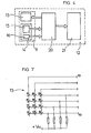
- Figure 4 is a diagram showing the different assemblies constituting the central unit of the device.
- FIG. 5 shows schematically and in the form of functional blocks all of the assemblies of the central unit.
- FIG. 6 represents in the form of functional blocks, the circuits associated with the read head, which shape the electrical pulses transmitted by the latter.
- Figure 7 shows the twelve-key matrix keyboard.
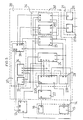
- FIG. 8 represents in the form of functional blocks the microprocessor of the circuit with its address locking and its reset circuit.
- FIG. 9 represents in the form of functional blocks the address decoding assembly.
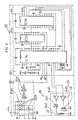
- FIG. 10 represents in the form of a functional block the random access memory of the processing unit.
- FIG. 11 shows the display block in the form of a functional block.
- FIG. 12 represents the clock in the form of functional blocks.
- FIG. 13 shows in the form of functional blocks an interface circuit serving as an input port.
- FIG. 14 shows in the form of functional blocks an interface circuit serving as an output port.
- Figure 15 shows the control sensors.
- Figure 16 shows the power controls for the outputs.
- FIGS 17 and 18 illustrate the flow of the access processes in the form of a flowchart.
- Figure 17 shows the procedure for a first access
- Figure 18 shows the procedure for a second access.
- Figures 19 to 22 show how the location of the lockers is carried out.
- Figure 19 is a diagram showing a top view of the locker rack.
- Figure 20 shows in perspective a detail of the tape drive with the coding tape
- Figure 21 is a partial top view of the bin coding strip.
- Figure 22 shows one of the tape drive's optocouplers.
- Figure 23 is a diagram showing a top view of the protective belt which surrounds the locker carousel
- Figure 24 is a diagram showing in top view the automatic closing of the locker door
- the device intended to implement said method.
- the power supplies of the different components have not been voluntarily represented. These power supplies are well known to those skilled in the art.
- the whole of the central unit comprises a certain number of circuits and electronic units which are interconnected by the terminations and links AA, BB, CC, DD, EE, FF, GG, HH, II, JJ, KK , LL, MM, NN, OO, PP, QQ, XX, YY.
- the protected access described will be a locker comprising lockers intended to receive skis. But it could be otherwise without departing from the scope of the invention.
- the protected site could just as well be hotel rooms, or changing rooms or safes.
- the user is therefore a skier who, to use the locker, must be authorized to do so and must, upon access, follow a determined process which will be described later.
- FIG. 5 represents the entire electronic assembly, which is advantageously arranged on a printed circuit of the electronic card type. Note also that the power supply is not shown either, but is intended to be supplied with alternating current of 220 Volts 50 Hertz or 110 Volts 60 Hertz or possibly direct current of 24 Volts (or even 5 or 12 Volts).
- the skier is the holder of an identification card (1) comprising a first identification code (Co 1).
- the coding of the information relating to the first identification is of the barcode type as shown in FIG. 1, 1c and 1d.
- the support is a cardboard or plastic card purchased by the skier or given to him or sold by the station when he purchases his pass.
- This card includes, in the context of its use for reading information, an area in which there is a group of white or black bars (2), wide or narrow, determining in a known manner either the first identification code (Co 1) .
- Each user is assigned an identification number which we will call the first identification code (Co 1).
- This first code comprising information relating to the site to which access is controlled, to a number assigned to each card holder, and an identification concerning the validity of the card.
- the card identification code is coded using 10 digits from 0 to 9 and the 16 digit positions indicate the following data:
- the first 7 digits constitute a serial code assigned to each card holder, the next 6 corresponding to the validity date, the next 2 to the site number, and the last to the verification character.
- the identification support specific to each user is, for example, an independent card made of plasticized cardboard or of plastic material as shown in FIGS. 1, 1a, 1b. But it could be otherwise as shown in Figure 1c according to which the first identification code (Co 1) is carried by a specific element (3) stuck on the package (4) that the skier must buy to be able to use ski lifts or, as shown in Figure 1d, incorporated in a plastic strap (100) pool type.
- the barcode to identify the user is a preferred solution because the coding of the cards is particularly easy and the reading quite reliable, but the first identification code (Co 1) can also be magnetic as shown in the figure. 1a.
- the identification card (1) then comprising a magnetic strip (5), the information of which would be read by an appropriate reader.
- the identification code can also be contained in an integrated circuit (6) as shown in FIG. 1b.
- the protected site is for example a ski locker (7) which includes an access door (9), mobile lockers (8) provided with a door (91) which is closed automatically by the door (9) as shown in FIG. 24, a protective belt (90) placed around the set of lockers which prevents the opening of the locker doors (91) inside the deposit system as shown in FIG. 23 and on the front wall (10) accessible by the user, the front (11) of the central unit (12).
- Said front panel (11) of the central unit comprising on the one hand a display screen (13) intended to ensure dialogue with the user and the code input unit (14) constituted by a matrix keyboard ( 15) and an optical card reader (16).
- the display (13) constituting the information unit serves as an interface between the device and the user. This information is therefore done visually, but it could be otherwise, because it could just as easily be audible.
- the barcode reader (16) is an optical reader compatible with virtually all barcode resolutions. It has a wide slot (17) which allows the possible use of thick cards. Its metal case (18) is hermetic to be able to be installed in a hostile environment, it is intended to operate in a wide temperature range such as for example from minus 40 degrees to plus 70 degrees, and has a unique power supply of 5 Volts. Reading takes place in an infrared spectrum.
- the reader may consist of an optical detector of the HBCS 7100 type, marketed by the company HEWLETT-PACKARD, and emits infrared radiation illuminating the bar code (2) of the card (1) inserted and moved into the slot (17) by transverse sliding. The reader transforming the reflected light into successive electrical signals, representative of the code bars.
- the implementation of infrared radiation making it possible to read a bar code even masked in whole or in part, by a protective film of polyvinyl chloride.
- the keyboard is waterproof and its internal organization is of the matrix type. It includes 12 keys (1, 2, 3, 4, 5, 6, 7, 8, 9, *, 0, &) allowing the user to enter a second identification code (19) called confidential code, as will be explained later.
- the central unit (12) also comprises a processing unit (20) and a detection and control unit (21) as can be seen more particularly. in Figure 4.
- the processing unit (20) comprises different units or circuits connected to each other. There is in particular a decoding assembly (22), a calculation unit (23), a random access memory (24), a clock (25), as well as a so-called “input and output port” unit (26) and an address decoding unit (27).
- the optical reader (16) is intended to read the first identification code (Co1) carried by the identification card (1) when the user passes his card through the slot (17), and transmits this to the information processing unit (20). Said reader (16) sends on its output (A) in response to the scrolling before it of the code bars, a succession of pulses which are processed in the decoding assembly (22) which is shown more particularly in FIG. 6. First of all the successions of pulses are shaped by the shaping circuit (28) which includes three protection diodes (D29) limiting overvoltages, and a resistor (R30) with two trigger-inverters (T31) type 74 LS 14 for filtering pulses.
- the shaping circuit (28) which includes three protection diodes (D29) limiting overvoltages, and a resistor (R30) with two trigger-inverters (T31) type 74 LS 14 for filtering pulses.
- the circuit (28) is connected to a decoding circuit (32) which transmits a binary code to the microprocessor (IC33) via the links (B).
- the decoding circuit comprises a first integrated circuit (IC34) of the HBCR2010 type with search for electrical signals announcing respectively the beginning and the end of the coded writing on the card with rejection of cards which do not include these two signals. Two other integrated circuits are associated with this first circuit (IC34).
- this decoding circuit (32) is associated with a signaling unit (37) allowing the user to know whether his card has been read.
- This circuit (37) includes a visual signaling circuit (38) and an audible signaling circuit (39).
- the visual signaling circuit comprising an amplifier (A40) connected in series with a light-emitting diode (D41) and a resistor (R42), while the sound signaling circuit comprises an amplifier (A43) connected in series with a sound transmitter ( 44).
- the light-emitting diode (D41) emitting a light of advantageously green color, and the sound signal confirming the validation of the operation.
- a microprocessor (IC33) of said calculation unit performs and controls the various operations for processing the information thus received.
- the microprocessor's execution program is contained in its read-only memory, programmed according to the desired functions. It contains all the instructions useful for the proper functioning of the electronic process. It is connected as we said previously to the decoding circuit by its links B and associated with an address locking circuit (IC46) called "latch", which first sends the address and then the data. he is connected on the one hand to the microprocessor by the link (I), and on the other hand to the RAM and to the clock by the links (K).
- the microprocessor (IC33) is connected on the one hand to the RAM (24) by the links (H, J, E, F), and on the other hand to the address decoding unit (27) by the bonds (D, E, F). On the other hand, it is associated with a reset circuit (47) comprising a resistor (R48), a capacitor (C49) and a push button (50) for manual reset. Furthermore, the keyboard (15) managed by the microprocessor (IC33) is directly connected to it by the links (C).
- the address decoding unit (27) shown in Figures 5 and 9, comprises three circuits.
- a first circuit (51) connected to the microprocessor (IC33) by the links (D) and to the random access memory (24) by the link (L), and comprising two integrated circuits (IC52) of the "74 LS 04" type, and two integrated circuits (IC53) of the "74 LS 08" type.
- the integrated circuit (IC 57) is connected to the clock (25) and to the address locking circuit (IC46) by the links (K).
- the address decoding unit divides the addressable space of the microprocessor for reading and writing in the various peripherals, i.e. the RAM, the display, the clock, and the input and Release.
- the random access memory (24) represented in FIGS. 5 and 10 comprises an integrated circuit (IC58) of the "MB 8464" type, which is connected, as we have already indicated to the microprocessor (IC33) by the links (G, H, J, E, F), and by the links (G, K) to the address locking circuit (IC46). RAM temporarily stores information.
- the display (13) consists of an integrated circuit (IC59) of the "LM 40255" type and is connected on the one hand to all of the circuits by its links (G) and to the integrated circuit (IC57) by the link (O). It is of the alphanumeric type made watertight by a nylon lens and informs the user of the various stages of the process in progress, and gives the necessary instructions.
- the clock (25) represented in FIG. 12 comprises an integrated circuit (IC60) of the "CDP 1879" type connected to the microprocessor by the links (J, H, G), and to the integrated circuit (IC57) of the decoding by the link (P).
- the clock is intended to transmit the date and time to the microprocessor when the latter needs it.
- the so-called “input and output port” unit (26) comprises two circuits, a first circuit (260) and a second circuit (261).
- the first circuit (260) comprises an integrated circuit (IC80) of the type 74 LS 573 connected to the microprocessor by the links G, and by the links H, J via an "OR” gate (P61) and a gate.
- IC80 integrated circuit
- P61 "OR" gate
- NAND P62
- P62 third circuit (56) of the address decoding unit (27) by the N link via the "OR” gate (P61).
- the second circuit (261) comprises an integrated circuit (IC81) of the type 74 LS 573 connected to the microprocessor by the links G, and by the links H, J via two "OR" gates (P64, P65) and a inverter (I63), and to the third circuit (56) of the address decoding unit (27) by the link M via the two "OR” gates (P64, P65).
- the integrated circuit (IC80) of the first circuit (260) is connected by the links Q to the various respective contacts of the capture and control unit (210), and the various links X of the integrated circuit (IC81) of the second. circuit (261) are connected to the control and power circuits (211).
- Each of the control and power circuits for the outputs includes three resistors (R66, R67, R68) a transistor (T69), an optocoupler (070), a diode (D71) and a relay (Re72) controlling a switch (In73) .
- the optocouplers are for example of the HCPL 2530 type from the company HEWLETT PACKARD, and the VMOS transistors are controlled in all or nothing voltage.
- the various contacts of the capture unit (210) can advantageously be optocouplers as explained below with reference to FIGS. 19 to 22.
- a coding strip (84).
- This strip moving with the lockers can be for example a strip pierced according to a coding, which will be read by a reader (83), constituted by a block of several optocouplers (830) of the fork type comprising a transmitter (em) and a receiver (re).
- Said reader (83) is mounted in a static position and controls the running of the coded strip (84) by reading the codes representing the numbers of the lockers.
- the coding is for example carried out by a succession of seven zones (a, b, c, d, e, f, g), which can be perforated or non-perforated.
- the coding reading is transmitted to the microprocessor (IC33) via the circuit (IC80).
- One of the coding methods consists in drilling the extreme zones (a and g) so that the first and the seventh optocoupler are assigned to the validation of the reading while the other five are used to identify the number of the locker.
- the access process takes place in three phases, and is shown schematically in Figures 17 and 18.
- FIG. 17 shows the method relating to a first access or to an input cycle (Ce). This is for example when the skier wants to use the locker for the first time or to store his skis.
- FIG. 18 shows the method relating to a second access or to an exit cycle (Cs). This is for example when the skier wants to remove his skis from the locker.
- Cs exit cycle
- FIG. 17 when the skier wants to store his skis, in the first phase (a) of the process, he passes his card (1) into the slot of the reader (16).
- the reading (La) of the first identification code (Co1) made by the reader is then decoded (Da), and the decoded information (Id) is checked (Va).
- Verification consists of verifying several things, if the first identification code (Co1) corresponds to an authorized user, that the deposit in which he wants to put his skis is indeed a possible and authorized deposit, and that the card is still valid at the time of use, and if the user performs an input cycle. If the first confidential code is refused (Ra) the access process is stopped, and there is reset (ro), to return the device to its initial state (EO).
- the user dials a second identification code or confidential code (Co2).
- This code during the first access is chosen arbitrarily by the user, it is four digits and it is personal.
- the user types this credit code (Co2) on the keyboard (15) by validating with the validation key (*).
- the confidential code (Co2) composed and validated is then stored in memory (Mb), which allows the user to continue the access process. He can therefore proceed to the next phase of the process, that is to say the third phase (c) which consists, for the user, of once again passing his identification card (1) into the optical reader (16).
- the reading (Lc) made by the reader is then decoded (Dc), and the decoded information (Id) is checked (Vc).
- the verification consists in determining whether the first identification code (2) corresponds to the first identification code having been used in the first phase (a) of the process. If the code is refused (Rc) the process must stop, and there is a loop through a reset (ro) to return the device to its initial state (EO). If the identification code is accepted (Ac), depositing is then authorized.
- a locker (8) is then assigned according to the uses. The number of this locker appears for example on the screen of the display (13), and simultaneously the affected locker (8) is positioned opposite the door (9), which opens. The skier then introduces his skis into the locker and closes the door by pressing a control push button. On his return, the removal of the skis from the locker will be done with an identical process, which will be called process or exit process in opposition to the entry access process.
- FIG. 18 in the first phase (a) of the process, he passes his card (1) into the slot of the reader (16).
- the reading (La) made by the reader is first of all decoded (Da), and the decoded information (Id) is checked (Va2).
- the verification consists in determining whether the first identification code (2) corresponds to an authorized user, and to a user who has put his skis in the locker. If the first confidential code is refused (Ra) the access process is stopped, and there is reset (ro), to return the device to its initial state (EO).
- the first confidential code is accepted (Aa) and corresponds to an authorized code, the following phase (b) is possible and effective.
- this second access phase (b) the user dials his confidential code (Co2).
- This code must of course correspond to that which had been chosen by the user when he first accessed.
- the confidential code entered is then stored in memory (Mb) to be checked at the end of the exit process.
- the next phase is then made mandatory to allow the completion of the control process.
- This third phase which is phase (c) of the method, consists in the user once again passing his identification card (1) into the optical reader (16).
- the reading (Lc) made by the reader is then decoded (Dc), and the decoded information (Id) is checked (Vc).
- the verification consists in determining if the first identification code (Co1) corresponds to the first identification code having been used in the first phase (a) of the exit process, and if the confidential code (Co2) introduced in the phase (b) is identical to that introduced during phase (b) of entry. If one of the codes is refused (Rc) the process is stopped, and there is reset (ro), to return the device to its initial state (EO). If the identification code (Co1) and the confidential code (Co2) are accepted, access to the locker is then authorized. In our example, the affected bin (8) is positioned opposite the door (9), which opens. The skier can then remove his skis from the locker and close the door. If there is refusal (Rc) in phase (c) note that the user can iron his card for a new exit process.
- the display indicates to the user the necessary information.
- This display is of the alphanumeric type of the type 2 lines of 40 letters is for example a display of "sharp" mark of reference LM 40 A 21.
- each card only allows access to one setpoint at a time, and that if the central unit has recorded an input and an output, said card becomes valid again for another cycle. Note also that if the operation cycle is carried out incompletely, voluntarily or not, at the end of a determined time, the central unit will cancel all the information entered. Likewise, the central unit will indicate which cycle phase the operator is in, in order to prevent possible partial and no-load manipulation of the system.
- the barcode reader recognizing the validity date on the code, validity cards limited or not, could be issued.
- a "pass" card with a specific procedure is used by the locker manager, to enable him to intervene directly in the operation of these. For example to initialize the system at the start of the season, with date and time setting, or to open one or more lockers, or to put it out of service.
Landscapes
- Physics & Mathematics (AREA)
- General Physics & Mathematics (AREA)
- Lock And Its Accessories (AREA)
- Information Transfer Between Computers (AREA)
- Jib Cranes (AREA)
- Pinball Game Machines (AREA)
- Semiconductor Integrated Circuits (AREA)
- Vehicle Body Suspensions (AREA)
Applications Claiming Priority (2)
| Application Number | Priority Date | Filing Date | Title |
|---|---|---|---|
| FR9001095A FR2657446B1 (fr) | 1990-01-24 | 1990-01-24 | Procede et dispositif destine a controler et a permettre l'acces a un site ou a un service. |
| FR9001095 | 1990-01-24 |
Publications (2)
| Publication Number | Publication Date |
|---|---|
| EP0443962A1 true EP0443962A1 (de) | 1991-08-28 |
| EP0443962B1 EP0443962B1 (de) | 1997-04-23 |
Family
ID=9393248
Family Applications (1)
| Application Number | Title | Priority Date | Filing Date |
|---|---|---|---|
| EP91420016A Expired - Lifetime EP0443962B1 (de) | 1990-01-24 | 1991-01-22 | Verfahren und Vorrichtung zum Kontrollieren und zum Gewähren des Zugangs zu einem Gelände oder einer Dienstleistung |
Country Status (4)
| Country | Link |
|---|---|
| EP (1) | EP0443962B1 (de) |
| AT (1) | ATE152269T1 (de) |
| DE (1) | DE69125742T2 (de) |
| FR (1) | FR2657446B1 (de) |
Cited By (4)
| Publication number | Priority date | Publication date | Assignee | Title |
|---|---|---|---|---|
| WO1996029684A1 (fr) * | 1995-03-21 | 1996-09-26 | S.E.R.P.I. - Societe D'etude De Recherche De Produits Industriels | Dispositif de consigne automatique pour bagages |
| FR2763154A1 (fr) * | 1996-05-17 | 1998-11-13 | Gerard Noel Marie Joseph | Procede de gestion de consigne a acces multiple |
| FR2784774A1 (fr) * | 1998-10-14 | 2000-04-21 | Yves Santi | Dispositif de consigne automatique et procedure d'acces associee |
| FR2807191A1 (fr) * | 2000-04-03 | 2001-10-05 | Jean Gatellier | Systeme de consigne pour deposer et recuperer un objet |
Families Citing this family (1)
| Publication number | Priority date | Publication date | Assignee | Title |
|---|---|---|---|---|
| DE10015732A1 (de) * | 2000-03-29 | 2001-10-11 | Skidata Ag | Zugangsberechtigungs-Buchungsverfahren |
Citations (8)
| Publication number | Priority date | Publication date | Assignee | Title |
|---|---|---|---|---|
| US3665162A (en) * | 1968-12-16 | 1972-05-23 | Omron Tateisi Electronics Co | Identification system |
| US3691350A (en) * | 1970-07-21 | 1972-09-12 | Roger J Kuhns | System for verifying authorized use of a credit card or the like |
| US3875375A (en) * | 1973-06-18 | 1975-04-01 | Frederick D Toye | Reader device for coded identification card |
| WO1983000578A1 (en) * | 1981-08-05 | 1983-02-17 | Ohlsson, Barth, Douglas | A locker |
| EP0122193A1 (de) * | 1983-04-08 | 1984-10-17 | Daniel Armand | Vorrichtung zum Reservieren von Tennisbahnen |
| WO1985001139A1 (en) * | 1983-08-25 | 1985-03-14 | Ncr Corporation | A system having controlled access thereto and a method of operating such a system |
| EP0169150A1 (de) * | 1984-07-20 | 1986-01-22 | Jacques Lewiner | Codiertes Sicherheitsschloss, insbesondere mit Tastatur |
| FR2605432A1 (fr) * | 1986-10-17 | 1988-04-22 | Arnaud Olivier | Dispositif de securite antivol a verrouillage automatique pour cycles stationnant sur la voie publique |
Family Cites Families (1)
| Publication number | Priority date | Publication date | Assignee | Title |
|---|---|---|---|---|
| FR2628870B1 (fr) * | 1988-03-21 | 1992-04-03 | Mors | Systeme de rangement a casiers adjacents commandes par un dispositif a microprocesseur |
-
1990
- 1990-01-24 FR FR9001095A patent/FR2657446B1/fr not_active Expired - Lifetime
-
1991
- 1991-01-22 EP EP91420016A patent/EP0443962B1/de not_active Expired - Lifetime
- 1991-01-22 AT AT91420016T patent/ATE152269T1/de not_active IP Right Cessation
- 1991-01-22 DE DE69125742T patent/DE69125742T2/de not_active Expired - Fee Related
Patent Citations (8)
| Publication number | Priority date | Publication date | Assignee | Title |
|---|---|---|---|---|
| US3665162A (en) * | 1968-12-16 | 1972-05-23 | Omron Tateisi Electronics Co | Identification system |
| US3691350A (en) * | 1970-07-21 | 1972-09-12 | Roger J Kuhns | System for verifying authorized use of a credit card or the like |
| US3875375A (en) * | 1973-06-18 | 1975-04-01 | Frederick D Toye | Reader device for coded identification card |
| WO1983000578A1 (en) * | 1981-08-05 | 1983-02-17 | Ohlsson, Barth, Douglas | A locker |
| EP0122193A1 (de) * | 1983-04-08 | 1984-10-17 | Daniel Armand | Vorrichtung zum Reservieren von Tennisbahnen |
| WO1985001139A1 (en) * | 1983-08-25 | 1985-03-14 | Ncr Corporation | A system having controlled access thereto and a method of operating such a system |
| EP0169150A1 (de) * | 1984-07-20 | 1986-01-22 | Jacques Lewiner | Codiertes Sicherheitsschloss, insbesondere mit Tastatur |
| FR2605432A1 (fr) * | 1986-10-17 | 1988-04-22 | Arnaud Olivier | Dispositif de securite antivol a verrouillage automatique pour cycles stationnant sur la voie publique |
Cited By (5)
| Publication number | Priority date | Publication date | Assignee | Title |
|---|---|---|---|---|
| WO1996029684A1 (fr) * | 1995-03-21 | 1996-09-26 | S.E.R.P.I. - Societe D'etude De Recherche De Produits Industriels | Dispositif de consigne automatique pour bagages |
| FR2763154A1 (fr) * | 1996-05-17 | 1998-11-13 | Gerard Noel Marie Joseph | Procede de gestion de consigne a acces multiple |
| FR2784774A1 (fr) * | 1998-10-14 | 2000-04-21 | Yves Santi | Dispositif de consigne automatique et procedure d'acces associee |
| FR2807191A1 (fr) * | 2000-04-03 | 2001-10-05 | Jean Gatellier | Systeme de consigne pour deposer et recuperer un objet |
| WO2001075822A1 (fr) * | 2000-04-03 | 2001-10-11 | Jean Gatellier | Systeme de consigne pour deposer et recuperer un objet |
Also Published As
| Publication number | Publication date |
|---|---|
| ATE152269T1 (de) | 1997-05-15 |
| EP0443962B1 (de) | 1997-04-23 |
| DE69125742T2 (de) | 1997-12-18 |
| FR2657446A1 (fr) | 1991-07-26 |
| DE69125742D1 (de) | 1997-05-28 |
| FR2657446B1 (fr) | 1992-04-24 |
Similar Documents
| Publication | Publication Date | Title |
|---|---|---|
| CA1060583A (fr) | Systeme pour memoriser des donnees dans un objet protatif independant | |
| EP0334726B1 (de) | Aufbewahrungsanlage mit durch eine Mikroprozessorvorrichtung gesteuerten Schliessfächern | |
| EP0389313B1 (de) | System zum Anordnen von benachbarten Schliessfächern mit Hilfe einer Mikroprozessoranordnung | |
| EP0044039B1 (de) | Individualisierter, tragbarer Gegenstand der Kreditkartenart | |
| FR2586447A1 (fr) | Dispositif de securite a acces multiples | |
| EP0359667B1 (de) | Verfahren zum Fernbestellen von verschiedenen, aus einem Katalog ausgewählten Waren oder Artikeln und zum Verfügungstellen derselben in einem Verkaufslokal und System zum Durchführen dieses Verfahrens | |
| EP0540095A1 (de) | Mikroschaltung für eine Chipkarte mit einem geschützten, programmierbaren Schalter | |
| CH641869A5 (fr) | Dispositif electronique de securite a combinaison de code modifiable et utilisation d'un tel dispositif. | |
| FR2662285A1 (fr) | Systeme de mise a disposition automatique et permanente de vehicules. | |
| FR2661021A1 (fr) | Systeme de rangement a casiers adjacents utilise notamment dans des gares ou des aeroports. | |
| EP0126699B1 (de) | Elektronische Identifizierungsvorrichtung | |
| EP0443962B1 (de) | Verfahren und Vorrichtung zum Kontrollieren und zum Gewähren des Zugangs zu einem Gelände oder einer Dienstleistung | |
| EP0065181B1 (de) | Verfahren zur elektronischen Identifikation | |
| EP0037566B1 (de) | Verfahren zur Identifikation, beispielsweise von Personen, im Zusammenhang mit der Ansteuerung einer Einrichtung | |
| FR2473755A1 (fr) | Procede et dispositif electronique de memorisation et de traitement confidentiel de donnees | |
| EP0065182A2 (de) | Verfahren zur elektronischen Identifikation | |
| EP0377535A1 (de) | Schliessfachschrank und Verfahren zum zeitlichen Übertragen eines Gegenstandes zwischen zwei Personen | |
| FR2738436A1 (fr) | Systeme de controle d'acces par cle electronique portable | |
| FR2615983A1 (fr) | Procede et dispositif de lecture de cartes d'identification portant des informations codees par un code a barres, notamment pour des systemes de controle d'acces et de gestion de site | |
| FR2613514A1 (fr) | Machine a voter electronique | |
| FR2805561A1 (fr) | Dispositif electronique permettant d'utiliser une combinaison a usage unique pour le deverrouillage d'une serrure electronique autonome | |
| FR2619941A1 (fr) | Systeme de controle de la liaison entre deux terminaux d'une installation de traitement de donnees | |
| FR2661446A1 (fr) | Serrure mecanique selectionnee, programmee, et asservie a distance au moyen de dispositifs de gestion d'acces, avec les cles standards a codes optiques qui lui sont destinees. | |
| EP0985790A1 (de) | Dynamisch gesteuertes elektronisches Schloss und mit einem solchen Schloss versehenes Steuerungssystem | |
| BE1006668A5 (fr) | Procede pour gerer les procedures de fermeture puis d'ouverture des organes de verrouillage qui protegent respectivement les acces a des milieux moyennant le paiement d'une somme d'argent. |
Legal Events
| Date | Code | Title | Description |
|---|---|---|---|
| PUAI | Public reference made under article 153(3) epc to a published international application that has entered the european phase |
Free format text: ORIGINAL CODE: 0009012 |
|
| AK | Designated contracting states |
Kind code of ref document: A1 Designated state(s): AT BE CH DE ES FR GB IT LI |
|
| 17P | Request for examination filed |
Effective date: 19920207 |
|
| 17Q | First examination report despatched |
Effective date: 19940202 |
|
| GRAG | Despatch of communication of intention to grant |
Free format text: ORIGINAL CODE: EPIDOS AGRA |
|
| GRAH | Despatch of communication of intention to grant a patent |
Free format text: ORIGINAL CODE: EPIDOS IGRA |
|
| GRAH | Despatch of communication of intention to grant a patent |
Free format text: ORIGINAL CODE: EPIDOS IGRA |
|
| GRAA | (expected) grant |
Free format text: ORIGINAL CODE: 0009210 |
|
| AK | Designated contracting states |
Kind code of ref document: B1 Designated state(s): AT BE CH DE ES FR GB IT LI |
|
| PG25 | Lapsed in a contracting state [announced via postgrant information from national office to epo] |
Ref country code: IT Free format text: LAPSE BECAUSE OF FAILURE TO SUBMIT A TRANSLATION OF THE DESCRIPTION OR TO PAY THE FEE WITHIN THE PRESCRIBED TIME-LIMIT;WARNING: LAPSES OF ITALIAN PATENTS WITH EFFECTIVE DATE BEFORE 2007 MAY HAVE OCCURRED AT ANY TIME BEFORE 2007. THE CORRECT EFFECTIVE DATE MAY BE DIFFERENT FROM THE ONE RECORDED. Effective date: 19970423 Ref country code: ES Free format text: THE PATENT HAS BEEN ANNULLED BY A DECISION OF A NATIONAL AUTHORITY Effective date: 19970423 Ref country code: AT Effective date: 19970423 |
|
| REF | Corresponds to: |
Ref document number: 152269 Country of ref document: AT Date of ref document: 19970515 Kind code of ref document: T |
|
| REG | Reference to a national code |
Ref country code: CH Ref legal event code: EP |
|
| REF | Corresponds to: |
Ref document number: 69125742 Country of ref document: DE Date of ref document: 19970528 |
|
| GBT | Gb: translation of ep patent filed (gb section 77(6)(a)/1977) |
Effective date: 19970929 |
|
| PLBE | No opposition filed within time limit |
Free format text: ORIGINAL CODE: 0009261 |
|
| STAA | Information on the status of an ep patent application or granted ep patent |
Free format text: STATUS: NO OPPOSITION FILED WITHIN TIME LIMIT |
|
| 26N | No opposition filed | ||
| REG | Reference to a national code |
Ref country code: FR Ref legal event code: RL |
|
| REG | Reference to a national code |
Ref country code: FR Ref legal event code: ST |
|
| PGFP | Annual fee paid to national office [announced via postgrant information from national office to epo] |
Ref country code: DE Payment date: 19990112 Year of fee payment: 9 |
|
| REG | Reference to a national code |
Ref country code: FR Ref legal event code: RN |
|
| REG | Reference to a national code |
Ref country code: FR Ref legal event code: FC |
|
| PGFP | Annual fee paid to national office [announced via postgrant information from national office to epo] |
Ref country code: CH Payment date: 20000113 Year of fee payment: 10 |
|
| PG25 | Lapsed in a contracting state [announced via postgrant information from national office to epo] |
Ref country code: DE Free format text: LAPSE BECAUSE OF NON-PAYMENT OF DUE FEES Effective date: 20000131 |
|
| PG25 | Lapsed in a contracting state [announced via postgrant information from national office to epo] |
Ref country code: LI Free format text: LAPSE BECAUSE OF NON-PAYMENT OF DUE FEES Effective date: 20010131 Ref country code: CH Free format text: LAPSE BECAUSE OF NON-PAYMENT OF DUE FEES Effective date: 20010131 |
|
| PGFP | Annual fee paid to national office [announced via postgrant information from national office to epo] |
Ref country code: GB Payment date: 20010209 Year of fee payment: 11 |
|
| PGFP | Annual fee paid to national office [announced via postgrant information from national office to epo] |
Ref country code: BE Payment date: 20010214 Year of fee payment: 11 |
|
| REG | Reference to a national code |
Ref country code: CH Ref legal event code: PL |
|
| REG | Reference to a national code |
Ref country code: GB Ref legal event code: IF02 |
|
| PGFP | Annual fee paid to national office [announced via postgrant information from national office to epo] |
Ref country code: FR Payment date: 20020121 Year of fee payment: 12 |
|
| PG25 | Lapsed in a contracting state [announced via postgrant information from national office to epo] |
Ref country code: GB Free format text: LAPSE BECAUSE OF NON-PAYMENT OF DUE FEES Effective date: 20020122 |
|
| PG25 | Lapsed in a contracting state [announced via postgrant information from national office to epo] |
Ref country code: BE Free format text: LAPSE BECAUSE OF NON-PAYMENT OF DUE FEES Effective date: 20020131 |
|
| BERE | Be: lapsed |
Owner name: DELATOUR PIERRE Effective date: 20020131 |
|
| GBPC | Gb: european patent ceased through non-payment of renewal fee |
Effective date: 20020122 |
|
| PG25 | Lapsed in a contracting state [announced via postgrant information from national office to epo] |
Ref country code: FR Free format text: LAPSE BECAUSE OF NON-PAYMENT OF DUE FEES Effective date: 20030930 |
|
| REG | Reference to a national code |
Ref country code: FR Ref legal event code: ST |