EP0444402A2 - Method and apparatus for indicating visibility in fog to drivers of motor vehicles - Google Patents
Method and apparatus for indicating visibility in fog to drivers of motor vehicles Download PDFInfo
- Publication number
- EP0444402A2 EP0444402A2 EP91100316A EP91100316A EP0444402A2 EP 0444402 A2 EP0444402 A2 EP 0444402A2 EP 91100316 A EP91100316 A EP 91100316A EP 91100316 A EP91100316 A EP 91100316A EP 0444402 A2 EP0444402 A2 EP 0444402A2
- Authority
- EP
- European Patent Office
- Prior art keywords
- road surface
- receiver
- car
- pulses
- fog
- Prior art date
- Legal status (The legal status is an assumption and is not a legal conclusion. Google has not performed a legal analysis and makes no representation as to the accuracy of the status listed.)
- Withdrawn
Links
Images
Classifications
-
- G—PHYSICS
- G01—MEASURING; TESTING
- G01S—RADIO DIRECTION-FINDING; RADIO NAVIGATION; DETERMINING DISTANCE OR VELOCITY BY USE OF RADIO WAVES; LOCATING OR PRESENCE-DETECTING BY USE OF THE REFLECTION OR RERADIATION OF RADIO WAVES; ANALOGOUS ARRANGEMENTS USING OTHER WAVES
- G01S17/00—Systems using the reflection or reradiation of electromagnetic waves other than radio waves, e.g. lidar systems
- G01S17/02—Systems using the reflection of electromagnetic waves other than radio waves
- G01S17/06—Systems determining position data of a target
- G01S17/42—Simultaneous measurement of distance and other co-ordinates
-
- G—PHYSICS
- G01—MEASURING; TESTING
- G01S—RADIO DIRECTION-FINDING; RADIO NAVIGATION; DETERMINING DISTANCE OR VELOCITY BY USE OF RADIO WAVES; LOCATING OR PRESENCE-DETECTING BY USE OF THE REFLECTION OR RERADIATION OF RADIO WAVES; ANALOGOUS ARRANGEMENTS USING OTHER WAVES
- G01S17/00—Systems using the reflection or reradiation of electromagnetic waves other than radio waves, e.g. lidar systems
- G01S17/87—Combinations of systems using electromagnetic waves other than radio waves
-
- G—PHYSICS
- G01—MEASURING; TESTING
- G01S—RADIO DIRECTION-FINDING; RADIO NAVIGATION; DETERMINING DISTANCE OR VELOCITY BY USE OF RADIO WAVES; LOCATING OR PRESENCE-DETECTING BY USE OF THE REFLECTION OR RERADIATION OF RADIO WAVES; ANALOGOUS ARRANGEMENTS USING OTHER WAVES
- G01S17/00—Systems using the reflection or reradiation of electromagnetic waves other than radio waves, e.g. lidar systems
- G01S17/88—Lidar systems specially adapted for specific applications
- G01S17/93—Lidar systems specially adapted for specific applications for anti-collision purposes
- G01S17/931—Lidar systems specially adapted for specific applications for anti-collision purposes of land vehicles
-
- G—PHYSICS
- G01—MEASURING; TESTING
- G01S—RADIO DIRECTION-FINDING; RADIO NAVIGATION; DETERMINING DISTANCE OR VELOCITY BY USE OF RADIO WAVES; LOCATING OR PRESENCE-DETECTING BY USE OF THE REFLECTION OR RERADIATION OF RADIO WAVES; ANALOGOUS ARRANGEMENTS USING OTHER WAVES
- G01S7/00—Details of systems according to groups G01S13/00, G01S15/00, G01S17/00
- G01S7/48—Details of systems according to groups G01S13/00, G01S15/00, G01S17/00 of systems according to group G01S17/00
- G01S7/481—Constructional features, e.g. arrangements of optical elements
- G01S7/4811—Constructional features, e.g. arrangements of optical elements common to transmitter and receiver
-
- G—PHYSICS
- G01—MEASURING; TESTING
- G01S—RADIO DIRECTION-FINDING; RADIO NAVIGATION; DETERMINING DISTANCE OR VELOCITY BY USE OF RADIO WAVES; LOCATING OR PRESENCE-DETECTING BY USE OF THE REFLECTION OR RERADIATION OF RADIO WAVES; ANALOGOUS ARRANGEMENTS USING OTHER WAVES
- G01S7/00—Details of systems according to groups G01S13/00, G01S15/00, G01S17/00
- G01S7/48—Details of systems according to groups G01S13/00, G01S15/00, G01S17/00 of systems according to group G01S17/00
- G01S7/483—Details of pulse systems
Definitions
- the invention relates to a method for determining the visibility for drivers when fog occurs according to the preamble of claims 1 and 2 and to an arrangement for performing this method.
- a method for monitoring the permeability of the atmosphere in which several measuring points, each equipped with a transmitter, receiver and warning board for corresponding displays, are provided along an automobile road at a distance of approximately 50 to 150 m.
- the transmitter and receiver of one measuring point point in opposite directions and each communicate with the receiver or transmitter of the next measuring point.
- the signal is generated by a light source, preferably a luminescent diode working in the infrared range.
- the attenuation of the electromagnetic radiation by fog occurring on the path from the transmitter of one measuring point to the receiver of the next measuring point is measured.
- DE 32 15 845 C1 and EP 0 092 825 show and describe in FIG. 7 a receiver of a distance sensor for projectile detonators consisting of several channels.
- This distance sensor is with one after Equipped with a laser rangefinder, which emits pulses in the direction of the target. It also contains a large number of receiving diodes corresponding to the number of measuring points, which convert the pulses reflected from the target into electrical signals. It then contains a scanning circuit which scans the received signals via scanning pulses which are synchronized with the transmission pulses, but which are short and delayed in a predetermined manner.
- a sequence of sampled values is generated which represent the amplitude values of successive received signals at different times of these signals.
- a phase modulation of the needle pulse is then necessary for monitoring a distance range, as can be seen in FIG. 8 and the associated description of both documents.
- the pulse generator can be used as a trigger for a monoflop stage, the time constant of which is varied by a modulation voltage.
- the needle pulse is then obtained from the trailing edge of the monoflop pulse. This technique is used in the present invention.
- the object of the invention is to provide the driver with largely conventional means of being able to estimate the existing visibility in the case of visual impairment due to fog. This object is achieved by the features mentioned in claims 1 and 2. Such a possibility, which can also be expanded, if necessary, to the extent that the relative speed to a preceding vehicle can be determined, is not yet on the market.
- a range finder 2 consisting of transmitter and receiver and operating according to the pulse transit time method is attached, which can be, for example, a laser range finder.
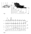
- This rangefinder is aligned with the road surface 3, which is divided into equidistant steps a to j on a corresponding panel, and can be pivoted in the joint 4 by angle ⁇ in elevation, either continuously or stepwise. The same movement can be carried out in many cases, mostly even more elegantly, by means of a scanning mirror, which is not shown here in the drawing.
- the range which corresponds approximately to the range of vision, is greater than the entire measuring distance j, so that the driver can drive in unhindered.
- the signal from point a reflects because the car is approaching the fog wall 5
- a plurality of range finders 2 can also be mounted in the front area of the car 1 one above the other and with different, but stepped inclination angles ⁇ to the road surface 3.
- several measuring beams are emitted at the same time, so that in the end the same information results for the driver. It is obvious that both variants shown only work if the course of the road in front of the vehicle is straight in the area of the measuring distance. The driver may therefore only sensibly operate the device if he believes that he is on a straight stretch of the road.
- a measurement of the relative speed between the car 1 with its range finder 2 and the target can also be combined with the visibility measurement described so far.
- all measurements aligned to the road surface 3 using the Doppler effect then show the vehicle speed.
- this obstacle determines or displays the visibility and the relative speed of one's own car with respect to this obstacle - provided there is sufficient visibility. This means that the relative speed of vehicles in front can also be determined in this way with the range finder in the absence of fog.
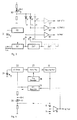
- the ten measuring points a to j of the road surface 3 can be assigned ten reception channels 11 to 21, the associated needle pulses 8 of which are delayed in time with respect to the transmission pulses 7 so that they are off 10, 20, 30 ... 100 m distance reflected transmission pulses coincide.
- the measuring beam of the transmitter containing the transmission signal is now deflected via a scanning mirror (not shown in the drawing) in such a way that it first hits the road surface 3 at a distance of 100 m and then comes closer and closer by tilting the mirror, the needle pulse is successively transmitted via the received pulses 7 'of the ten channels 11 to 21 are running, each channel reporting the arrival of its needle pulse. The otherwise necessary phase modulation of the needle pulse is not necessary here.
- Monitoring electronics now only need to determine which channel has received signals.
- the pulse generator 22 (FIG. 3) generates a voltage, so that the transmitter diode 31 emits the signal pulse 7 (FIG. 2) after optoelectronic conversion.
- a small part of the pulse-shaped driver voltage is decoupled and after passing through the delay elements 24 'to used as needle pulse 8 according to FIG. 2b.
- the delay times 25 (FIG. 2) are set in such a way that they correspond to the predetermined path of the signal pulses to be detected from the transmitting diode 31 to the destination, that is to say the roadway ceiling 3, and back again to the receiving diode 30.
- the device In order to determine the relative speed mentioned above, the device must be switched to another operating mode.
- the scanning mirror stands still in the position that corresponds to the furthest distance. Now only one of the ten reception channels 11 to 21 needs to be used.
- the pulse generator 22 can be used as a trigger for the monoflop stage 27, the time constant of which is varied by a modulation voltage of the modulation generator 28.
- the needle pulse is then obtained again from the trailing edge of the monoflop pulse.
- the area to be monitored can be set as required.
- the envelope of the signal contains the information about the relative speed sought, while in the second case it results from the distance and time measurement that has taken place.
- the scanning mirror can be replaced in the following way:
- any optical means for example a cylindrical lens
- the transmission and reception beam are expanded in the vertical direction in such a way that all ten measurement points a to j are detected.
- a chopper is arranged in front of or behind the optics, which modulates the transmit or receive beam in a simple manner such that a yes / no statement about possibly in the 100 Hz rhythm in all 10 channels (11-21) Obstacles are created.
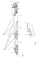
- the car 1 shown with solid lines runs at a certain distance behind the truck 1 '.
- the laser transmission and reception module 2 which operates according to the pulse transit time method, is fastened, the optical axis of which can be pivoted in a plane vertical to the direction of travel by means of an opto-mechanical or electro-optical element (not shown in the drawing).
- the reflections occurring in positions a to n of the road surface 3 are made visually and / or acoustically recognizable to the driver in the interior of the car after corresponding optoelectronic conversion and signal processing on the display 32 (FIG. 7).
- the signal processing can include an expansion and averaging of the reflected signal over a series of successive laser pulses, as is understood by the term “sampling method”. In this respect, it is known prior art.
- Equation (1) when applied to FIG. 1 means: By forming the quotinet of equations (2) and (3) with constant output power P:
- the total readout time in the assumed example is 25.6 microseconds, which is well adapted to the maximum laser pulse repetition frequency.
- E.g. drives 5 from position a to position b and looking at the signals coming from position c, the change in the signal - apart from geometric factors - only results from the change in atmospheric attenuation, that is to say the reflection factor ⁇ has no influence on a change (more precisely: the quotient) of the signals (see Eq. 5).
- the latter depends, in particular with a flat angle of incidence and observation, essentially on the weather-related road condition, i.e. the dryness, wetness or a possible ice layer. In principle, this method also makes it possible to make a statement about the condition of the road surface that is important for a driver.
- the receiving module part is equipped with a polarization switch, so that separately reflected radiation can then be measured with a polarization axis parallel to the linearly polarized transmission beam and perpendicular to it.
- the degree of depolarization of the radiation is determined, which also depends on the condition of the road surface: A dry roadway causes a strong, wet or icy roadway a lower depolarization.
- the visibility can also be determined using the proposed measures if the radiation is reflected by the truck 1 'driving ahead (FIG. 5) or by other objects on or next to the carriageway 3. If the speed does not correspond to the range of vision, the driver is warned acoustically via the display 12 and / or if necessary.
- the measuring system of the rear vehicle 1 with the speed v 1 will give a warning if the relative speed to the vehicle 1 ', v 1 - v 2, exceeds a value dependent on the visibility.
- the system of vehicle 2 warns when the road - as shown - makes a sharp bend, the bend cannot be seen or cannot be seen immediately and at the same time the speed is too high.
- Obstacles can be identified here by the discontinuity of the distance indicated in FIG. 5 - car 1 is shown at two distances from the truck 1 ′ driving ahead: the system scans the measuring points a to n. In the case of an open road, the distance increases in a systematic manner, the exact course depending on changes in the road inclination and the pitch angle of the vehicle, but the general course is comparable. An obstacle interrupts this course and is recognized as such.
- the standard range of vision V n is a clearly defined variable.
- the actual visually relevant visibility depends on various environmental parameters, such as the ambient brightness or the brightness of the road surface. This can be determined in a simple manner by measuring the DC current on the line branch 39, 40 in FIG. 7 and used to calculate the real visibility.
Landscapes
- Physics & Mathematics (AREA)
- Engineering & Computer Science (AREA)
- Electromagnetism (AREA)
- Computer Networks & Wireless Communication (AREA)
- General Physics & Mathematics (AREA)
- Radar, Positioning & Navigation (AREA)
- Remote Sensing (AREA)
- Optical Radar Systems And Details Thereof (AREA)
- Measurement Of Optical Distance (AREA)
Abstract
Verfahren zum Ermitteln der Sichtweite für Autofahrer beim Auftreten von Nebel unter Verwendung eines aus Sender und Empfänger bestehenden Entfernungsmessers. Für eine solche Sichtweiten-Ermittlung wird im Frontbereich eines Autos entweder ein in der Elevation verschwenkbarer Entfernungsmesser oder es werden ihrer mehrere starr übereinander liegend installiert, so daß im ersten Fall der Entfernungsmesser durch Verschwenken des Gerätes in Elevation und im anderen durch gleichzeitiges Abstrahlen aller Entfernungsmesser die in äquidistante Schritte unterteilte, unmittelbar vor dem Auto liegende Meßstrecke bestrahlt wird, wobei die Information darin besteht, daß nur von den vom Nebel bedeckten Meßpunkten der Fahrbahndecke keine Reflexion zum Empfänger hin erfolgt
Description
Die Erfindung bezieht sich auf ein Verfahren zum Ermitteln der Sichtweite für Autofahrer beim Auftreten von Nebel nach dem Oberbegriff der Ansprüche 1 und 2 sowie auf eine Anordnung zur Durchführung dieses Verfahrens.The invention relates to a method for determining the visibility for drivers when fog occurs according to the preamble of
Aus der DE-PS 22 23 230 ist ein Verfahren zur Überwachung der Durchlässigkeit der Atmosphäre bekannt, bei dem entlang einer Autostraße im Abstand von etwa 50 bis 150 m mehrere jeweils mit Sender, Empfänger und Warntafel für entsprechende Anzeigen ausgerüstete Meßstellen vorgesehen sind. Sender und Empfänger einer Meßstelle weisen hierbei in entgegengesetzte Richtung und kommunizieren jeweils mit Empfänger bzw. Sender der nächsten Meßstelle. Das Signal wird hierbei von einer Lichtquelle, vorzugsweise einer im Infrarotbereich arbeitenden Lumineszenzdiode, erzeugt. Die auf der Wegstrecke vom Sender der einen Meßstelle zum Empfänger der nächsten Meßstelle auftretende Dämpfung der elektromagnetischen Strahlung durch Nebel wird gemessen. Sodann wird die Frequenz dieser Strahlung in jedem Meßabschnitt durch die Dämpfung des vorhergehenden Abschnitts festgelegt und schließlich wird aus der Dämpfung und der Frequenz der Strahlung in einem bestimmten Meßabschnitt eine am Anfang eines jeden Meßabschnitts erscheinende Anzeige abgeleitet, die Auskunft über eine etwaige Veränderung der Durchlässigkeit der Atmosphäre gegenüber dem Vorabschnitt erteilt. Eine solche an sich zuverlässig funktionierende Anlage ist ortsgebunden und wegen ihres Aufwands nur an bestimmten, besonders nebelgefährdeten Stellen einsetzbar.From DE-PS 22 23 230 a method for monitoring the permeability of the atmosphere is known, in which several measuring points, each equipped with a transmitter, receiver and warning board for corresponding displays, are provided along an automobile road at a distance of approximately 50 to 150 m. The transmitter and receiver of one measuring point point in opposite directions and each communicate with the receiver or transmitter of the next measuring point. The signal is generated by a light source, preferably a luminescent diode working in the infrared range. The attenuation of the electromagnetic radiation by fog occurring on the path from the transmitter of one measuring point to the receiver of the next measuring point is measured. The frequency of this radiation in each measuring section is then determined by the attenuation of the preceding section and finally an indication appearing at the beginning of each measuring section is derived from the attenuation and the frequency of the radiation in a given measuring section, which provides information about any change in the permeability of the Atmosphere given to the previous section. Such a system, which functions reliably in itself, is localized and, because of its complexity, can only be used at certain, particularly fog-prone locations.
Die DE 32 15 845 C1 bzw. EP 0 092 825 zeigen und beschreiben in ihrer Fig. 7 einen aus mehreren Kanälen bestehenden Empfänger eines Abstandssensors für Geschoßzünder. Dieser Abstandssensor ist mit einem nach dem Impulslaufzeitverfahren arbeitenden Laserentfernungsmesser ausgerüstet, dessen Sender Impulse in Richtung Ziel abstrahlt. Außerdem enthält er der Anzahl der Meßstellen entsprechend viele Empfangsdioden, die die vom Ziel reflektierten Impulse in elektrische Signale umwandeln. Sodann enthält er eine Abtastschaltung, die über mit den Sendeimpulsen synchronisierte, gegenüber diesen jedoch kurz ausgebildete und in vorgegebener Weise verzögerte Abtastimpulse die Empfangssignale abtastet. Auf diese Weise wird im Fall einer Relativbewegung zwischen Sensor und Ziel und der damit verbundenen Phasenverschiebung zwischen Empfangssignalen und Nadelimpulsen eine Folge von Abtastwerten erzeugt, die die Amplitudenwerte aufeinanderfolgender Empfangssignale zu jeweils unterschiedlichen Zeitpunkten dieser Signale repräsentieren. Für die Überwachung eines Entfernungsbereiches ist sodann eine Phasenmodulation des Nadelimpulses notwendig, wie sie Fig. 8 und zugehöriger Beschreibung beider Druckschriften zu entnehmen ist. Der Impulsgenerator kann dabei als Trigger für eine Monoflopstufe verwendet werden, deren Zeitkonstante durch eine Modulationsspannung variiert wird. Aus der Rückflanke des Monoflopimpulses wird dann der Nadelimpuls gewonnen. Von dieser Technik wird in der vorliegenden Erfindung Gebrauch gemacht.
Aufgabe der Erfindung ist es, für den Autofahrer mit weitgehend herkömmlichen Mitteln eine Möglichkeit zu schaffen, bei Sehbehinderung durch Nebel die bestehende Sichtweite abschätzen zu können. Diese Aufgabe wird erfindungsgemäß durch die in den Ansprüchen 1 und 2 genannten Merkmale gelöst. Eine solche Möglichkeit, die sich bedarfsweise auch noch dahingehend erweitern läßt, daß man die Relativgeschwindigkeit zu einem vorausgehenden Fahrzeug feststellen kann, ist bisher nicht auf dem Markt.The object of the invention is to provide the driver with largely conventional means of being able to estimate the existing visibility in the case of visual impairment due to fog. This object is achieved by the features mentioned in
Im folgenden werden an Hand einer Zeichnung Ausführungsbeispiele der Erfindung näher erläutert, wobei die in den einzelnen Figuren einander entsprechenden Teile dieselben Bezugszahlen aufweisen. Es zeigt
- Fig. 1
- eine Prinzipskizze des erfindungsgemäßen Verfahrens,
- Fig. 2
- das Impulsdiagramm eines herkömmlichen, in der HF-Oszillographie verwendeten Abtastverfahrens mittels eines Nadelimpulses,
- Fig. 3
- das Blockschaltbild des Empfängers bei gleichzeitiger Bestrahlung mehrerer Meßpunkte der Fahrbahndecke,
- Fig. 4
- das Blockschaltbild für die Bestrahlung eines ganzen Entfernungsbereiches,
- Fig. 5
- eine weitere Prinzipskizze des erfindungsgemäßen Verfahrens mit eingezeichneten Berechnungsdaten,
- Fig. 6
- das generelle Prinzip-Blockschaltbild für Beispiel gemäß Fig. 5,
- Fig. 7
- das empfangsseitige Blockschaltbild für Beispiel gemäß Fig. 5 und
- Fig. 8
- einen speziellen Anwendungsfall der Erfindung für die eine Fahrtrichtung einer Autobahn.
- Fig. 1
- a schematic diagram of the method according to the invention,
- Fig. 2
- 1 shows the pulse diagram of a conventional scanning method using a needle pulse used in HF oscillography,
- Fig. 3
- the block diagram of the receiver with simultaneous irradiation of several measuring points of the road surface,
- Fig. 4
- the block diagram for the irradiation of an entire distance range,
- Fig. 5
- another schematic diagram of the method according to the invention with drawn-in calculation data,
- Fig. 6
- the general principle block diagram for example according to FIG. 5,
- Fig. 7
- the reception-side block diagram for example according to FIGS. 5 and
- Fig. 8
- a special application of the invention for the direction of travel of a highway.
Im Frontbereich des Autos 1 der Fig. 1 ist ein aus Sender und Empfänger bestehender und nach dem Impulslaufzeitverfahren arbeitender Entfernungsmesser 2, der z.B. ein Laserentfernungsmesser sein kann, befestigt. Dieser Entfernungsmesser ist auf die auf einem entsprechenden Tableau in äquidistante Schritte a bis j unterteilte Fahrbahndecke 3 ausgerichtet und in dem Gelenk 4 um Winkel α in der Elevation verschwenkbar, und zwar entweder kontinuierlich oder stufenweise. Dieselbe Bewegung kann in vielen Fällen, und zwar zumeist sogar eleganter, mittels eines hier zeichnerisch allerdings nicht dargestellten Abtastspiegels ausgeführt werden. Solange bei einem solchen Verschwenkvorgang die Fahrbahndeck 3 in allen Positionen des Entfernungsmessers ein ausreichend hohes Signal zum Empfänger reflektiert, ist die Reichweite, die angenähert der Sichtweite entspricht, größer als die gesamte Meßstrecke j, so daß der Fahrer ungehindert zufahren kann. Reflektiert hingegen beispielsweise nur noch das Signal von Punkt a, weil sich das Auto nämlich der Nebelwand 5 nähert, so bedeutet dies, daß die Sichtweite bereits kleiner als die Meßstrecke b ist und für den Autofahrer somit größte Vorsicht geboten ist.In the front area of the
Bei einem anderen, zeichnerisch nicht dargestellten Ausführungsbeispiel können im Frontbereich des Autos 1 auch mehrere Entfernungsmesser 2 übereinander und mit unterschiedlichen, jedoch gegeneinander abgestuften Neigungswinkeln α zur Fahrbahndecke 3 montiert sein. In diesem Fall werden gleichzeitig mehrere Meßstrahlen ausgesandt, so daß sich für den Autofahrer im Endeffekt die gleiche Information ergibt. Es liegt auf der Hand, daß beide aufgezeigten Varianten nur funktionieren, wenn der Straßenverlauf vor dem Fahrzeug im Bereich der Meßentfernung gerade verläuft. Der Autofahrer darf demnach die Vorrichtung sinnvoll nur betätigen, wenn er sich auf einem geraden Stück Wegstrecke glaubt.In another embodiment, not shown in the drawing, a plurality of
Mit der bisher beschriebenen Sichtweitmessung läßt sich im Bedarfsfall auch eine Messung der relativen Geschwindigkeit zwischen dem Auto 1 mit seinem Entfernungsmesser 2 und dem Ziel kombinieren. Hierbei zeigen dann alle auf die Fahrbahndecke 3 ausgerichteten Messungen unter Ausnutzung des Dopplereffekts die Fahrzeuggeschwindigkeit. Befindet sich jedoch zwischen Entfernungsmesser und Fahrbahndecke ein Hindernis 5, so wird einerseits durch dieses Hindernis die Sichtweite und zum anderen auch die Relativgeschwindigkeit des eigenen Autos in bezug auf dieses Hindernis bestimmt bzw. angezeigt - ausreichende Sichtweite vorausgesetzt. Dies bedeutet, daß auf diese Weise mit dem Entfernungsmesser bei Abwesenheit von Nebel auch die Relativgeschwindigkeit vorausfahrender Fahrzeuge ermittelt werden kann.If necessary, a measurement of the relative speed between the
Da nun aber komplette Laserentfernungsmesser als Massenprodukt der Autoindustrie noch vergleichsweise teuer sind, bietet sich eine - für den vorgesehenen Zweck immer noch ausreichend genaue - Sichtweitenmessung mit folgenden Gerätekomponenten unter Ausnutzung des optoelektronischen Verfahrens gemäß DE 32 15 845 C1 bzw. EP 0 092 825 an: In Fig. 2a soll ein Signal, dessen Folgefrequenz bekannt ist, empfangen werden. Zu diesem Zweck wird gemäß Fig. 2b ein Empfangstast- oder Nadelimpuls 8 (im Laborjargon auch als Samplingimpuls bezeichnet) erzeugt, der die gleiche Folgefrequenz aufweist wie der zu empfangende Signalimpuls, jedoch gegenüber diesem phasenmoduliert ist. Hierdurch trifft er von Periode zu Periode mit einem anderen Momentanwert des Signalimpulses zusammen. Über eine Diode - es sind dies die Samplingdioden 6 bis
der Fig. 3 - werden beide Impulse, Signalimpuls 7 und Nadelimpuls 8, auf einen Kondensator - in Fig.3 die Kondensatoren 9 bis
- gegeben, so daß am Ausgang des zwischen Diode und Kondensator geschalteten Verstärkers - in Fig. 3 die Positionen 10 bis
- die aus Fig. 2c ersichtliche Sägezahnspannung 26 entsteht, deren Spitzenamplitude der Summe beider Momentanwerte entspricht. Wäre das Eingangssignal Null, so würde sich ein Spannungsverlauf nach Fig. 2d ergeben. Bei Vorhandensein des Signalimpulses entsteht ein niederfrequentes Signal 29, das gemäß Fig. 2e einem zeitlich gedehnten Originalimpuls entspricht. Das in diesem Absatz Gesagte ist Stand der Technik und dient lediglich der Erläuterung des sogenannten Samplingverfahrens, das im Rahmen der vorliegenden Erfindung wie folgt zum Einsatz gelangt:However, since complete laser rangefinders are still comparatively expensive as a mass product in the automotive industry, a range of vision measurement - which is still sufficiently accurate for the intended purpose - with the following device components using the optoelectronic method according to
of Fig. 3 - both pulses,
- Given so that at the output of the between diode and capacitor switched amplifier - in Fig. 3
- The
Sollen z.B. Sichtweiten bis etwa 100 m erfaßt werden, kann man gemäß Fig. 1 und 3 den zehn Meßpunkten a bis j der Fahrbahndecke 3 zehn Empfangskanäle 11 bis 21 zuordnen, deren zugehörige Nadelimpulse 8 gegenüber den Sendeimpulsen 7 zeitlich so verzögert werden, daß sie mit den aus 10, 20, 30 ... 100 m Entfernung reflektierten Sendeimpulsen zusammenfallen. Wird nun der das Sendesignal enthaltende Meßstrahl des Senders über einen Abtastspiegel (zeichnerisch nicht dargestellt) so abgelenkt, daß er zunächst in 100 m Entfernung auf die Fahrbahndecke 3 trifft und dann durch Kippen des Spiegels immer näher kommt, so wird der Nadelimpuls nacheinander über die Empfangsimpulse 7' der zehn Kanäle 11 bis 21 laufen, wobei jeder Kanal das Eintreffen seines Nadelimpulses meldet. Die sonst notwendige Phasenmodulation des Nadelimpulses ist hier also nicht nötig. Eine überwachungselektronik braucht jetzt nur noch festzustellen, welcher Kanal noch Signale erhalten hat.Should e.g. Visibility up to about 100 m can be detected, according to FIGS. 1 and 3, the ten measuring points a to j of the
Die hierzu und zum Verständnis erforderliche Elektronik ist wieder Teil des vorerwähnten Samplingverfahrens und somit nicht Gegenstand der Erfindung. Hierbei erzeugt der Impulsgenerator 22 (Fig. 3) eine Spannung, so daß die Sendediode 31 nach optoelektronischer Umwandlung den Signalimpuls 7 (Fig. 2) aussendet. Ein kleiner Teil der impulsförmigen Treiberspannung wird ausgekoppelt und nach Durchlaufen der Verzögerungsglieder 24' bis![]()
als Nadelimpuls 8 gemäß Fig. 2b verwendet. Die Verzögerungszeiten 25 (Fig. 2) werden dabei so eingestellt, daß sie dem zu detektierenden vorbestimmten Weg der Signalimpulse von der Sendediode 31 zum Ziel, sprich Fahrbahndecke 3, und wieder zurück zur Empfangsdiode 30 entsprechen.The electronics required for this and for understanding are again part of the aforementioned sampling method and are therefore not the subject of the invention. Here, the pulse generator 22 (FIG. 3) generates a voltage, so that the transmitter diode 31 emits the signal pulse 7 (FIG. 2) after optoelectronic conversion. A small part of the pulse-shaped driver voltage is decoupled and after passing through the delay elements 24 'to ![]()
used as
Fährt ein mit einem solchen Sensor ausgerüstetes Auto 1 eine Straße entlang, so wird kein Signal empfangen, solange es nicht mit dem Nadelimpuls 8 zusammentreffen kann. Durch die Bewegung des Abtastspiegels, läuft das von der Fahrbahndecke 3 reflektierte Signal mit der Spiegelbewegung über den Nadelimpuls hinweg und wird von diesem abgetastet.If a
Um die vorstehend erwähnte Relativgeschwindigkeit zu ermitteln, muß das Gerät in einen anderen Betriebsmode geschaltet werden. Hierbei steht der Abtastspiegel still, und zwar in derjenigen Position, die der weitesten Entfernung entspricht. Jetzt braucht nur noch einer der zehn Empfangskanäle 11 bis 21 benutzt werden. Hierfür ist zunächst eine gleichfalls wieder für sich genommen aus DE 32 15 845 C1 und EP 0 092 825 bekannte Phasenmodulation des Nadelimpulses 8 gemäß Fig. 4 notwendig. Der Impulsgenerator 22 kann dabei als Trigger für die Monoflopstufe 27 verwendet werden, deren Zeitkonstante durch eine Modulationsspannung des Modulationsgenerators 28 variiert wird. Aus der Rückflanke des Monoflopimpulses wird dann wieder der Nadelimpuls gewonnen. Der zu überwachende Bereich kann hierbei beliebig eingestellt werden. Er kann sowohl von Punkt "a" bis zur maximalen Reichweite "j" als auch auf einen Bereich zwischen zwei Entfernungen eingestellt werden. Hierbei wird - je nach Vorgabe - entweder die Impulsbreite gemessen oder aber es finden mehrere Entfernungsmessungen statt, wobei dann die Unterschiede in den einzelnen Entfernungen gemessen werden müssen. Im ersten Fall enthält die Umhüllende des Signals die Information über die gesuchte Relativgeschwindigkeit, während sie sich im zweiten Fall aus der erfolgten Weg- und Zeitmessung ergibt.In order to determine the relative speed mentioned above, the device must be switched to another operating mode. The scanning mirror stands still in the position that corresponds to the furthest distance. Now only one of the ten
Bei einem weiteren, zeichnerisch nicht dargestellten Ausführungsbeispiel läßt sich der Abtastspiegel in folgender Weise ersetzen: Mit irgendwelchen optischen Mitteln, z.B. einer zylindrischen Linse, werden Sende- und Empfangsstrahl in vertikaler Richtung so aufgeweitet, daß alle zehn Meßpunkte a bis j erfaßt werden. Vor oder hinter der Optik ist ein Chopper angeordnet, der den Sende- oder Empfangsstrahl in einfacher Weise dergestalt moduliert, daß etwa im 100-Hz-Rhythmus in allen 10 Kanälen (11 - 21) eine Ja/Nein-Aussage über evtl. in der Meßstrecke vorhandene Hindernisse entsteht.In a further exemplary embodiment, not shown in the drawing, the scanning mirror can be replaced in the following way: With any optical means, for example a cylindrical lens, the transmission and reception beam are expanded in the vertical direction in such a way that all ten measurement points a to j are detected. A chopper is arranged in front of or behind the optics, which modulates the transmit or receive beam in a simple manner such that a yes / no statement about possibly in the 100 Hz rhythm in all 10 channels (11-21) Obstacles are created.
In Fig. 5 fährt der mit ausgezogener Linienführung dargestellte PKW 1 mit einem bestimmtem Abstand hinter dem LKW 1'. Im Frontbereich des PKWs ist der nach dem Impulslaufzeitvefahren arbeitende Lasersende- und Empfangsmodul 2 befestigt, dessen optische Achse sich durch ein zeichnerisch nicht näher dargestelltes opto-mechanisches oder elektrooptisches Element in einer zur Fahrtrichtung vertikalen Ebene verschwenken läßt. Die hierbei auftretenden Reflexionen in den Positionen a bis n der Fahrbahndecke 3 werden im Inneren des PKWs nach entsprechender optoelektronischer Umformung und Signalverarbeitung auf der Anzeige 32 (Fig. 7) visuell und/oder akustisch dem Autofahrer kenntlich gemacht. Die Signalverarbeitung kann eine Dehnung und Mittelung des reflektierten Signals über eine Reihe aufeinanderfolgender Laserimpulse einschließen wie dies unter dem Begriff des Samplingverfahrens verstanden wird. Insofern handelt es sich um bekannten Stand der Technik.In Fig. 5 the
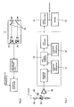
Die Ausgangsleistung P wird vorzugsweise durch die Empfangsdiode 35 (Fig. 6 und 7) mittels der Lichtbrücke 36 gemessen, die über einen Satz halbdurchlässiger Spiegel oder - bei einem anderen, zeichnerisch nicht dargestellten Ausführungsbeispiel - durch eine Glasfaserverbindung einen definierten Teil der Ausgangsstrahlung auf die Empfangsdiode lenkt. Das empfangene, auf P normierte Signal E/P ist abhängig von der Entfernung ri, bei der die Reflexion erfolgt, von dem Reflexionskoeffizienten ρ der Fahrbahndecke 3 und dem Extinktionskoeffizienten σ der Atmosphäre und ergibt sich rechnerisch zu:

wobei
- ri =
- Entfernung der reflektierenden Fläche vor dem PKW
- ρ =
- Reflexionskoeffizient der Fahrbahndecke
- σ =
- Extinktionskoeffizient der Atmosphäre
- Vn =
- Normsichtweite, d.h. diejenige Strecke, auf der die
Transmission den Wert 2 % (oder 5 %) annimmt.
Grundsätzlich sind nur Sichtweiten von maximal ca. 200 m von Interesse. Die genaue Entfernung ri ist über die Laufzeit bekannt, während ein genauer Wert des Reflexionskoeffizienten ρ bei richtiger Wahl der Entfernung von untergeordnetem Einfluß ist. Am einfachsten dürfte es ein, wenn man für ρ eine plausible Annahme trifft. Bei der Berechnung des Extinktionskoeffizienten σ dagegen eliminiert man gemäß Gleichung (5) den a priori unbekannten Reflexionskoeffizienten ρ durch Messung der Reflexion vom selben Ort - z.B. von Position c in Fig. 1 - aus unterschiedlicher Entfernung. Hiervon abgesehen ist der Wert des empfangenen Signals E/P ein direktes Maß für den Extinktionskoeffizienten σ, wobei letzterer mit der Normsichtweite Vn durch die Beziehung Vn = k/σ verknüpft ist.The output power P is preferably measured by the receiving diode 35 (FIGS. 6 and 7) by means of the
in which
- r i =
- Removal of the reflective surface in front of the car
- ρ =
- Reflection coefficient of the road surface
- σ =
- Extinction coefficient of the atmosphere
- V n =
- Standard range of vision, ie the distance on which the transmission assumes the
value 2% (or 5%).
Basically, only a maximum visibility of about 200 m is of interest. The exact distance r i is known over the transit time, while an accurate value of the reflection coefficient ρ is of minor influence if the distance is selected correctly. It would be easiest if one makes a plausible assumption for ρ. When calculating the extinction coefficient σ, on the other hand, the equation (5) is used to eliminate the a priori unknown reflection coefficient ρ by measuring the reflection from the same location - for example from position c in FIG. 1 - from a different distance. Apart from this, the value of the received signal E / P is a direct measure of the extinction coefficient σ, the latter being linked to the standard visual range V n by the relationship V n = k / σ.
Gleichung (1) bedeutet in Anwendung auf Fig. 1:
Durch Quotinetenbildung der Gleichungen (2) und (3) ergibt sich bei konstanter Ausgangsleistung P :
By forming the quotinet of equations (2) and (3) with constant output power P:
Eine größere Effektivität und Flexibilität läßt sich nun gemäß der Erfindung durch folgende die Signalverarbeitung 37 der Fig. 7 betreffende Maßnahmen erzielen: Nach Detektion des Signals durch die Empfangsdiode 35, seiner optronischen Umwandlung und seiner Verstärkung im Vorverstärker 38 wird das Signal dem CCD-Schieberegister 32 (CCD = Charge Coupled _Device), einem Ladungskoppelelement, zugeführt. Letzteres verfügt über zwei getrennte Eingangs-/Ausgangs-Taktgeneratoren 10 und 11.Greater effectiveness and flexibility can now be achieved according to the invention by the following measures relating to the
Wird nun das CCD-Schieberegister 32 z.B. mit einem Eingangstakt von 100 MHz geladen, so wird bei 128 verfügbaren Stufen ein Zeitraum von 1,28 µs gespeichert, was einer Entfernung von 192 m entspricht (Auflösung: 10 ns = 1,5 m). Wird das CCD-Schieberegister dagegen mit einer Taktrate von nur 5 MHz ausgelsen (Signaldehnung: Faktor 20), so kann - als zweiter Schritt - eine Weiterverarbeitung mit Bausteinen geringerer Bandbreite und damit auch geringerer Kosten durchgeführt werden. Die Gesamtauslesezeit beträgt im angenommenen Beispiel 25,6 µs, was an die maximale Laser-Pulsfolgefrequenz gut angepaßt ist.If the
Als weitere (analoge und/oder digitale) Signalverarbeitung kann nun die an sich bekannte und vorstehend bereits erwähnte Mittelung über mehrere Laserimpulse bis ca. 100 ms sowie die Ermittlung einer Ausgangskurve für Signale als Funktion verschiedener Entfernungen erfolgen. Hieraus ergibt sich ein Verlauf, der für den Extinktionskoeffizienten σ typisch ist. Bei geeigneter Signalverarbeitung, speziell einer sogenannten r²-Korrektur, ist die Ausgleichskurve eine Gerade, sofern die atmosphärischen Bedingungen konstant sind. Abweichungen hiervon lassen im Fall von Nebel darauf schließen, daß derselbe in einer bestimmten Entfernung vor dem PKW 1 (Fig. 5) dichter zu werden beginnt. Unter r² -Korrektur versteht man die Multiplikation der Signale mit dem Quadrat der Entfernung. Bei konstanten Umgebungsbedingungen und einer halblogarithmischen Darstellung ergibt sich eine lineare Abhängigkeit. Die Steigung dieser Geraden ist direkt proportional dem Extinktionskoeffizienten σ. Eine elektronische, prozessorgestützte Auswertung der Signale aus verschiedenen Entfernungen erlaubt eine Bestimmung von σ ohne vorausgehende Bestimmung von E/P. Für die Praxis ergibt sich dadurch die Möglichkeit einer Früherkennung vor dichter werdendem Nebel.As further (analog and / or digital) signal processing, the averaging, known per se and already mentioned above, can now take place over several laser pulses up to approximately 100 ms, and the determination of an output curve for signals as a function of different distances. This results in a curve that is typical of the extinction coefficient σ. With suitable signal processing, especially a so-called r² correction, the compensation curve is a straight line, provided the atmospheric conditions are constant. Deviations from this in the case of fog suggest that it begins to become denser at a certain distance in front of the car 1 (FIG. 5). R² correction is the multiplication of the signals by the square of the distance. With constant ambient conditions and a semi-logarithmic representation, there is a linear dependency. The slope of this line is directly proportional to the extinction coefficient σ. An electronic, processor-supported evaluation of the signals from different distances enables a determination of σ without prior determination of E / P. In practice, this results in the possibility of early detection before the fog becomes thicker.
Fährt z.B. der PKW 1 in Fig. 5 von Position a nach Position b und betrachtet man die Signale, die von Position c kommen, so rührt die Änderung des Signals - von geometrischen Faktoren abgesehen - nur von der Änderung der atmosphärischen Dämpfung her, das heißt der Reflexionsfaktor ρ hat keinen Einfluß auf eine Änderung (genauer: den Quotienten) der Signale(s.Gl. 5). Hiermit läßt sich der Extinktionskoeffizient σ genauer bestimmen und damit wiederum der Reflexionsfaktor ρ der Fahrbahndecke 3. Derselbe hängt speziell bei flachem Einfalls- und Beobachtungswinkel im wesentlichen vom witterungsbedingten Straßenzustand, also der Trockenheit, Nässe oder einem eventuellen Eisbelag ab. Diese Methode ermöglicht demnach prinzipiell auch eine Aussage über die für einen Kraftfahrer wichtigen Zustandsverhältnisse der von ihm befahrenen Fahrbahndecke.E.g. drives 5 from position a to position b and looking at the signals coming from position c, the change in the signal - apart from geometric factors - only results from the change in atmospheric attenuation, that is to say the reflection factor ρ has no influence on a change (more precisely: the quotient) of the signals (see Eq. 5). This enables the extinction coefficient σ to be determined more precisely, and in turn the reflection factor ρ of the
Bei einem anderen, zeichnerisch nicht dargestellten Ausführungsbeispiel ist es ferner vorstellbar, daß das Empfangsmodulteil mit einer Polarisationsweiche ausgerüstet ist, so daß dann separat reflektierte Strahlung mit einer Polarisationsachse parallel zum linear polarisierten Sendestrahl und senkrecht zu diesem gemessen werden kann. Auf diese Weise wird der Depolarisationsgrad der Strahlung festgestellt, der auch wieder vom Zustand der Fahrbahndecke abhängt: Eine trockene Fahrbahn bewirkt eine starke, eine nasse oder vereiste Fahrbahn dagegen eine geringere Depolarisation.In another embodiment, not shown in the drawing, it is also conceivable that the receiving module part is equipped with a polarization switch, so that separately reflected radiation can then be measured with a polarization axis parallel to the linearly polarized transmission beam and perpendicular to it. In this way, the degree of depolarization of the radiation is determined, which also depends on the condition of the road surface: A dry roadway causes a strong, wet or icy roadway a lower depolarization.
Die Sichtweite kann mit den vorgeschlagenen Maßnahmen auch bestimmt werden, wenn die Strahlung von dem vorausfahrenden LKW 1' (Fig. 5) oder von anderen Objekten auf oder neben der Fahrbahn 3 reflektiert wird. Entspricht hierbei die Geschwindigkeit nicht der Sichtweite, wird der Fahrer über die Anzeige 12 und/oder gegebenenfalls auch akustisch gewarnt.The visibility can also be determined using the proposed measures if the radiation is reflected by the truck 1 'driving ahead (FIG. 5) or by other objects on or next to the
Ein zusätzliches Problem bei herkömmlichen Kollisionswarnsystemen ergibt sich durch die Falschalarme. Im anstehenden Fall bietet sich hierfür folgende Umgehungsmöglichkeit an: Man geht davon aus, daß Hindernisse, deren Entfernung deutlich kleiner als die Sichtweite ist, gesehen werden, so daß in diesen Fällen eine Warnung nicht notwendig ist. Gefährlich sind hingegen Objekte, die bei nicht angepaßter Geschwindigkeit eine Entfernung haben, die in etwa der Sichtweite entspricht oder deren Entfernung größer als die Sichtweite ist. Letzterer Fall setzt natürlich voraus, daß das Sichtweitemeßsystem eine Reichweite besitzt, die größer ist als diejenige der Sichtweite. Das Ausführungsbeispiel gemäß Fig. 8 möge dies verdeutlichen:An additional problem with conventional collision warning systems arises from the false alarms. In the upcoming case, the following workaround is possible: It is assumed that obstacles, the distance of which is significantly smaller than the visual range, are seen, so that a warning is not necessary in these cases. Objects, on the other hand, are dangerous if they are at a distance that is roughly the same as the visual range or whose distance is greater than the visual range when the speed is not adjusted. The latter case, of course, assumes that the visual range measurement system has a range that is greater than that of the visual range. The embodiment according to FIG. 8 may clarify this:
Das Meßsystem des hinteren Fahrzeugs 1 mit der Geschwindigkeit v₁ wird eine Warnung abgeben, wenn die Relativgeschwindigkeit zum Fahrzeug 1', v₁ - v₂, einen sichtweiteabhängigen Wert überschreitet. Das System des Fahrzeugs 2 warnt, wenn die Straße - wie dargestellt - eine scharfe Biegung macht, die Biegung nicht oder nicht sofort gesehen werden kann und gleichzeitig die Geschwindigkeit zu hoch ist. Hindernisse können hier durch die in Fig. 5 angedeutete Diskontinuität der Entfernung - PKW 1 ist in zwei Entfernungen zum vorausfahrenden LKW 1'dargestellt - erkannt werden: Das System tastet die Meßpunkte a bis n ab. Hierbei vergrößert sich bei freier Straße die Entfernung in systematischer Weise, wobei der genaue Verlauf zwar von Änderungen der Straßenneigung und dem Nickwinkel des Fahrzeugs abhängt, der generelle Verlauf aber vergleichbar ist. Ein Hindernis unterbricht diesen Verlauf und wird dadurch als solches erkannt.The measuring system of the
Die Normsichtweite Vn schließlich ist eine eindeutig definierte Größe. Die tatsächliche visuell relevante Sichtweite hängt von verschiedenen Umweltparametern ab, wie z.B. der Umgebungshelligkeit bzw. der Helligkeit der Fahrbahndecke. Diese kann in einfacher Weise durch Messen des DC-Stroms an dem Leitungszweig 39, 40 in Fig. 7 ermittelt und zur Berechnung der reellen Sichtweite verwendet werden.Finally, the standard range of vision V n is a clearly defined variable. The actual visually relevant visibility depends on various environmental parameters, such as the ambient brightness or the brightness of the road surface. This can be determined in a simple manner by measuring the DC current on the
Claims (16)
dadurch gekennzeichnet, daß
characterized in that
Applications Claiming Priority (4)
| Application Number | Priority Date | Filing Date | Title |
|---|---|---|---|
| DE4005919 | 1990-02-24 | ||
| DE4005919A DE4005919C2 (en) | 1990-02-24 | 1990-02-24 | Method and arrangement for determining the visibility for motorists when fog occurs |
| DE4016973 | 1990-05-25 | ||
| DE4016973A DE4016973C1 (en) | 1990-02-24 | 1990-05-25 |
Publications (2)
| Publication Number | Publication Date |
|---|---|
| EP0444402A2 true EP0444402A2 (en) | 1991-09-04 |
| EP0444402A3 EP0444402A3 (en) | 1993-01-13 |
Family
ID=25890509
Family Applications (1)
| Application Number | Title | Priority Date | Filing Date |
|---|---|---|---|
| EP19910100316 Withdrawn EP0444402A3 (en) | 1990-02-24 | 1991-01-11 | Method and apparatus for indicating visibility in fog to drivers of motor vehicles |
Country Status (4)
| Country | Link |
|---|---|
| US (1) | US5118180A (en) |
| EP (1) | EP0444402A3 (en) |
| JP (1) | JPH04215089A (en) |
| DE (1) | DE4016973C1 (en) |
Cited By (3)
| Publication number | Priority date | Publication date | Assignee | Title |
|---|---|---|---|---|
| WO1994012893A1 (en) * | 1992-11-20 | 1994-06-09 | Gec-Marconi Avionics (Holdings) Limited | Vehicle reversing aid |
| EP0691534A1 (en) * | 1994-07-06 | 1996-01-10 | Volkswagen Aktiengesellschaft | Method of visibility determination in particular for vehicle movement |
| CN103180794A (en) * | 2010-07-26 | 2013-06-26 | 联邦科学和工业研究组织 | Three-dimensional scanning beam system and method |
Families Citing this family (35)
| Publication number | Priority date | Publication date | Assignee | Title |
|---|---|---|---|---|
| DE4137551A1 (en) * | 1990-03-10 | 1993-03-11 | Daimler Benz Ag | View improving appts., partic. for vehicle - converts impinging light into output signals in reception optic depending on distance. |
| DE4106289A1 (en) * | 1991-02-28 | 1992-09-03 | Bayerische Motoren Werke Ag | TEST METHOD FOR THE VISIBILITY ON ROADWAYS AND DEVICE FOR IMPLEMENTING THE METHOD |
| DE4124192A1 (en) * | 1991-07-20 | 1993-01-21 | Dornier Luftfahrt | Optical rangefinder for spacing between moving road vehicles - measures propagation time of infrared reflection from preceding vehicle, and gives warning of too near approach |
| DE4233379C1 (en) * | 1992-10-05 | 1994-03-31 | Leica Ag Heerbrugg | Method and device for determining the relative visibility |
| US5546188A (en) * | 1992-11-23 | 1996-08-13 | Schwartz Electro-Optics, Inc. | Intelligent vehicle highway system sensor and method |
| US5321490A (en) * | 1992-11-23 | 1994-06-14 | Schwartz Electro-Optics, Inc. | Active near-field object sensor and method employing object classification techniques |
| DE4301228C1 (en) * | 1993-01-19 | 1994-04-21 | Daimler Benz Ag | Procedure for determining visibility |
| US5354981A (en) * | 1993-07-14 | 1994-10-11 | Loral Fairchild Corporation | Switching photosensitive matrix device |
| DE4324308C1 (en) * | 1993-07-20 | 1994-12-22 | Bayerische Motoren Werke Ag | Process for determining visibility in thick fog and visibility sensor |
| JP3294726B2 (en) * | 1994-12-20 | 2002-06-24 | 本田技研工業株式会社 | Radar equipment |
| DE19931825A1 (en) * | 1999-07-08 | 2001-01-25 | Bosch Gmbh Robert | Visibility measurement device |
| DE19955249A1 (en) * | 1999-11-17 | 2001-05-23 | Bosch Gmbh Robert | Visibility measurement procedure |
| US6563432B1 (en) * | 2001-01-12 | 2003-05-13 | Safegate International Ab | Aircraft docking system and method with automatic checking of apron and detection of fog or snow |
| WO2004092395A2 (en) * | 2003-04-08 | 2004-10-28 | Baylor College Of Medicine | Modulators of telomere stability |
| JP3994941B2 (en) * | 2003-07-22 | 2007-10-24 | オムロン株式会社 | Radar equipment for vehicles |
| DE10337006A1 (en) * | 2003-08-12 | 2005-03-10 | Continental Ag | Method and device for improving the ride comfort of motor vehicles |
| DE102004045329A1 (en) * | 2004-09-16 | 2006-04-06 | Siemens Ag | Transportation with night vision system |
| JP4725391B2 (en) * | 2006-03-29 | 2011-07-13 | 株式会社デンソー | Visibility measuring device for vehicle and driving support device |
| JP4940458B2 (en) * | 2007-08-10 | 2012-05-30 | 本田技研工業株式会社 | Object detection device |
| US8087589B2 (en) * | 2007-11-02 | 2012-01-03 | Intermec Ip Corp. | Laser barcode scanner employing heterodyning techniques |
| US8010316B2 (en) | 2008-12-11 | 2011-08-30 | Intermec Ip Corp. | System and method for laser range-finding |
| CN101886928A (en) * | 2009-05-14 | 2010-11-17 | 深圳富泰宏精密工业有限公司 | Portable electronic device with guiding function |
| DE102009046597A1 (en) | 2009-11-11 | 2011-05-12 | Robert Bosch Gmbh | Light detecting and ranging system's atmospheric influences reducing method for driver assistant system for detecting pedestrian in surrounding of motor vehicle, involves determining whether object is stationary object or movable object |
| EP2722684B1 (en) * | 2012-10-19 | 2019-08-28 | Sick Ag | Laser scanner |
| US9239959B1 (en) | 2013-04-08 | 2016-01-19 | Lockheed Martin Corporation | Multi-resolution, wide field-of-view, unmanned ground vehicle navigation sensor |
| SE537280C2 (en) * | 2013-07-18 | 2015-03-24 | Scania Cv Ab | Interpretation of measuring point detected by an optical sensor |
| CN104966298A (en) * | 2015-06-17 | 2015-10-07 | 南京大学 | Night low-cloud heavy-mist monitoring method based on low-light cloud image data |
| JP2016001182A (en) * | 2015-07-21 | 2016-01-07 | コモンウェルス サイエンティフィック アンド インダストリアル リサーチ オーガナイゼーション | Three-dimensional scanning beam system and method |
| DE102015112103B4 (en) | 2015-07-24 | 2025-09-18 | Preh Gmbh | Detection device for fog detection for a motor vehicle |
| JP6868570B2 (en) | 2015-12-21 | 2021-05-12 | 株式会社小糸製作所 | Vehicle and vehicle image acquisition method equipped with vehicle image acquisition device, control device, vehicle image acquisition device or control device |
| CN108431629B (en) | 2015-12-21 | 2022-07-08 | 株式会社小糸制作所 | Vehicle image acquisition device, control device, vehicle including vehicle image acquisition device or control device, and vehicle image acquisition method |
| EP3396411A4 (en) | 2015-12-21 | 2019-08-21 | Koito Manufacturing Co., Ltd. | Image acquisition device for vehicles, and vehicle provided with same |
| US11194023B2 (en) | 2015-12-21 | 2021-12-07 | Koito Manufacturing Co., Ltd. | Image acquiring apparatus for vehicle, control device, vehicle having image acquiring apparatus for vehicle or control device, and image acquiring method for vehicle |
| US20200081102A1 (en) * | 2018-09-10 | 2020-03-12 | Robotic Research, Llc | Ladar for military and harsh environment use |
| CN115616530B (en) * | 2022-12-16 | 2023-03-31 | 青岛镭测创芯科技有限公司 | Laser radar optical scanning device |
Family Cites Families (13)
| Publication number | Priority date | Publication date | Assignee | Title |
|---|---|---|---|---|
| SE358478B (en) * | 1970-11-16 | 1973-07-30 | Asea Ab | |
| DE2223230C3 (en) * | 1972-05-12 | 1975-04-30 | Eltro Gmbh Gesellschaft Fuer Strahlungstechnik, 6900 Heidelberg | Procedure for monitoring the permeability of the atmosphere |
| ZA801538B (en) * | 1979-03-19 | 1981-04-29 | United Kingdom Government | Method and apparatus for estimating slant visibility in fog |
| JPS5876784A (en) * | 1981-10-31 | 1983-05-09 | Nissan Motor Co Ltd | Light pulse radar apparatus for vehicles |
| JPS58155379A (en) * | 1982-03-12 | 1983-09-16 | Kimio Yamawaki | Light doppler radar |
| DE3215845C1 (en) * | 1982-04-28 | 1983-11-17 | Eltro GmbH, Gesellschaft für Strahlungstechnik, 6900 Heidelberg | Distance sensor for a projectile igniter |
| JPS5917182A (en) * | 1982-07-20 | 1984-01-28 | Nissan Motor Co Ltd | Optical radar device for detecting road surface condition |
| CA1235773A (en) * | 1983-12-23 | 1988-04-26 | Shigeto Nakayama | Device for detecting road surface condition |
| JPS6123985A (en) * | 1984-07-13 | 1986-02-01 | Nissan Motor Co Ltd | Detecting device for distance between vehicles |
| JPS62231189A (en) * | 1986-04-01 | 1987-10-09 | Nissan Motor Co Ltd | Speed calculating device |
| DE3635396A1 (en) * | 1986-10-17 | 1988-04-28 | Bayerische Motoren Werke Ag | DEVICE FOR DETECTING OBSTACLES FOR MOTOR VEHICLES |
| DE3735267C3 (en) * | 1987-10-17 | 1996-03-21 | Telefunken Microelectron | Visibility measurement device |
| DE3738221A1 (en) * | 1987-11-11 | 1989-06-08 | Bayerische Motoren Werke Ag | METHOD AND DEVICE FOR DETECTING THE STATE OF A ROAD |
-
1990
- 1990-05-25 DE DE4016973A patent/DE4016973C1/de not_active Expired - Fee Related
-
1991
- 1991-01-11 EP EP19910100316 patent/EP0444402A3/en not_active Withdrawn
- 1991-02-22 JP JP3028705A patent/JPH04215089A/en active Pending
- 1991-02-22 US US07/660,440 patent/US5118180A/en not_active Expired - Fee Related
Cited By (5)
| Publication number | Priority date | Publication date | Assignee | Title |
|---|---|---|---|---|
| WO1994012893A1 (en) * | 1992-11-20 | 1994-06-09 | Gec-Marconi Avionics (Holdings) Limited | Vehicle reversing aid |
| EP0691534A1 (en) * | 1994-07-06 | 1996-01-10 | Volkswagen Aktiengesellschaft | Method of visibility determination in particular for vehicle movement |
| CN103180794A (en) * | 2010-07-26 | 2013-06-26 | 联邦科学和工业研究组织 | Three-dimensional scanning beam system and method |
| US9146315B2 (en) | 2010-07-26 | 2015-09-29 | Commonwealth Scientific And Industrial Research Organisation | Three dimensional scanning beam system and method |
| CN103180794B (en) * | 2010-07-26 | 2017-02-15 | 联邦科学和工业研究组织 | Three-dimensional scanning beam system and method |
Also Published As
| Publication number | Publication date |
|---|---|
| JPH04215089A (en) | 1992-08-05 |
| EP0444402A3 (en) | 1993-01-13 |
| US5118180A (en) | 1992-06-02 |
| DE4016973C1 (en) | 1991-06-13 |
Similar Documents
| Publication | Publication Date | Title |
|---|---|---|
| EP0444402A2 (en) | Method and apparatus for indicating visibility in fog to drivers of motor vehicles | |
| DE19531632B4 (en) | distance measuring | |
| EP0396865B1 (en) | Optical radar | |
| EP2191298B1 (en) | Method for determining a distance by means of an optoelectronic image sensor | |
| EP0785883B1 (en) | Sensor for determining visual range and rain cover | |
| DE4040894C1 (en) | Motor vehicle parking aid using pulsed laser - evaluates signal reflected from obstacle and received by semiconductor diode at rear corner of vehicle | |
| EP2800982A1 (en) | Method and device for measuring the speed of a vehicle independently of the wheels | |
| DE3827729A1 (en) | COLLISION WARNING DEVICE FOR MOTOR VEHICLES | |
| DE4005919C1 (en) | Ascertaining range of vision of car driver in fog - using range finder transmitting signals and receiving those reflected from road surface not covered by fog | |
| DE2229887A1 (en) | METHOD OF MEASURING THE DISTANCE FROM AND THE SPEED COMPONENT OF AN OBJECT VERTICAL TO A REFERENCE LINE | |
| DE102019127667A1 (en) | Distance measuring optoelectronic sensor and method for detecting a target object | |
| DE102015217912A1 (en) | Method for calibrating the runtime of a lidar sensor | |
| EP0814348A2 (en) | Method for measuring the distance between a vehicle and an object | |
| EP0811855A2 (en) | Sensor system for automatic relative position control | |
| EP2221640B1 (en) | Method for measuring the speed of a vehicle and visual allocation in documentation | |
| EP0139707A1 (en) | Device for detecting other vehicles in the rear vision field of a vehicle | |
| DE102004031024B4 (en) | Optical sensor | |
| EP3591424A1 (en) | 3d radiated light camera and method for recording three-dimensional image data | |
| DE10138531A1 (en) | Recording system for three-dimensional distance-measurement image for surface of object measures time for propagating light with short-term integrated photodetector | |
| DE102005003191A1 (en) | Motor vehicle e.g. passenger car`s, surrounding field detecting device for parking spot measurement, has light source and camera arranged with basis distance from one another, which serves to determine distance between vehicle and obstacle | |
| EP4252026B1 (en) | Method for operating a detection device for determining temperature-adjusted distance variables, corresponding detection device, and vehicle having at least one detection device of this kind | |
| DE3225474C2 (en) | Method of target recognition | |
| EP1684094A2 (en) | Method of optical triangulation for determining distance in automotive applications | |
| DE102023117446B3 (en) | optical system | |
| DE19910501A1 (en) | Method for determining speed of vehicle by using transceiver that detects reflected signals of its output signal from objects of environment of vehicle for modifying value of first speed |
Legal Events
| Date | Code | Title | Description |
|---|---|---|---|
| PUAI | Public reference made under article 153(3) epc to a published international application that has entered the european phase |
Free format text: ORIGINAL CODE: 0009012 |
|
| AK | Designated contracting states |
Kind code of ref document: A2 Designated state(s): DE FR GB IT SE |
|
| PUAL | Search report despatched |
Free format text: ORIGINAL CODE: 0009013 |
|
| AK | Designated contracting states |
Kind code of ref document: A3 Designated state(s): DE FR GB IT SE |
|
| STAA | Information on the status of an ep patent application or granted ep patent |
Free format text: STATUS: THE APPLICATION IS DEEMED TO BE WITHDRAWN |
|
| 18D | Application deemed to be withdrawn |
Effective date: 19930910 |