EP0444402A2 - Méthode et appareil pour indiquer aux automobilistes la limite de visibilité dans le brouillard - Google Patents
Méthode et appareil pour indiquer aux automobilistes la limite de visibilité dans le brouillard Download PDFInfo
- Publication number
- EP0444402A2 EP0444402A2 EP91100316A EP91100316A EP0444402A2 EP 0444402 A2 EP0444402 A2 EP 0444402A2 EP 91100316 A EP91100316 A EP 91100316A EP 91100316 A EP91100316 A EP 91100316A EP 0444402 A2 EP0444402 A2 EP 0444402A2
- Authority
- EP
- European Patent Office
- Prior art keywords
- road surface
- receiver
- car
- pulses
- fog
- Prior art date
- Legal status (The legal status is an assumption and is not a legal conclusion. Google has not performed a legal analysis and makes no representation as to the accuracy of the status listed.)
- Withdrawn
Links
Images
Classifications
-
- G—PHYSICS
- G01—MEASURING; TESTING
- G01S—RADIO DIRECTION-FINDING; RADIO NAVIGATION; DETERMINING DISTANCE OR VELOCITY BY USE OF RADIO WAVES; LOCATING OR PRESENCE-DETECTING BY USE OF THE REFLECTION OR RERADIATION OF RADIO WAVES; ANALOGOUS ARRANGEMENTS USING OTHER WAVES
- G01S17/00—Systems using the reflection or reradiation of electromagnetic waves other than radio waves, e.g. lidar systems
- G01S17/02—Systems using the reflection of electromagnetic waves other than radio waves
- G01S17/06—Systems determining position data of a target
- G01S17/42—Simultaneous measurement of distance and other co-ordinates
-
- G—PHYSICS
- G01—MEASURING; TESTING
- G01S—RADIO DIRECTION-FINDING; RADIO NAVIGATION; DETERMINING DISTANCE OR VELOCITY BY USE OF RADIO WAVES; LOCATING OR PRESENCE-DETECTING BY USE OF THE REFLECTION OR RERADIATION OF RADIO WAVES; ANALOGOUS ARRANGEMENTS USING OTHER WAVES
- G01S17/00—Systems using the reflection or reradiation of electromagnetic waves other than radio waves, e.g. lidar systems
- G01S17/87—Combinations of systems using electromagnetic waves other than radio waves
-
- G—PHYSICS
- G01—MEASURING; TESTING
- G01S—RADIO DIRECTION-FINDING; RADIO NAVIGATION; DETERMINING DISTANCE OR VELOCITY BY USE OF RADIO WAVES; LOCATING OR PRESENCE-DETECTING BY USE OF THE REFLECTION OR RERADIATION OF RADIO WAVES; ANALOGOUS ARRANGEMENTS USING OTHER WAVES
- G01S17/00—Systems using the reflection or reradiation of electromagnetic waves other than radio waves, e.g. lidar systems
- G01S17/88—Lidar systems specially adapted for specific applications
- G01S17/93—Lidar systems specially adapted for specific applications for anti-collision purposes
- G01S17/931—Lidar systems specially adapted for specific applications for anti-collision purposes of land vehicles
-
- G—PHYSICS
- G01—MEASURING; TESTING
- G01S—RADIO DIRECTION-FINDING; RADIO NAVIGATION; DETERMINING DISTANCE OR VELOCITY BY USE OF RADIO WAVES; LOCATING OR PRESENCE-DETECTING BY USE OF THE REFLECTION OR RERADIATION OF RADIO WAVES; ANALOGOUS ARRANGEMENTS USING OTHER WAVES
- G01S7/00—Details of systems according to groups G01S13/00, G01S15/00, G01S17/00
- G01S7/48—Details of systems according to groups G01S13/00, G01S15/00, G01S17/00 of systems according to group G01S17/00
- G01S7/481—Constructional features, e.g. arrangements of optical elements
- G01S7/4811—Constructional features, e.g. arrangements of optical elements common to transmitter and receiver
-
- G—PHYSICS
- G01—MEASURING; TESTING
- G01S—RADIO DIRECTION-FINDING; RADIO NAVIGATION; DETERMINING DISTANCE OR VELOCITY BY USE OF RADIO WAVES; LOCATING OR PRESENCE-DETECTING BY USE OF THE REFLECTION OR RERADIATION OF RADIO WAVES; ANALOGOUS ARRANGEMENTS USING OTHER WAVES
- G01S7/00—Details of systems according to groups G01S13/00, G01S15/00, G01S17/00
- G01S7/48—Details of systems according to groups G01S13/00, G01S15/00, G01S17/00 of systems according to group G01S17/00
- G01S7/483—Details of pulse systems
Definitions
- the invention relates to a method for determining the visibility for drivers when fog occurs according to the preamble of claims 1 and 2 and to an arrangement for performing this method.
- a method for monitoring the permeability of the atmosphere in which several measuring points, each equipped with a transmitter, receiver and warning board for corresponding displays, are provided along an automobile road at a distance of approximately 50 to 150 m.
- the transmitter and receiver of one measuring point point in opposite directions and each communicate with the receiver or transmitter of the next measuring point.
- the signal is generated by a light source, preferably a luminescent diode working in the infrared range.
- the attenuation of the electromagnetic radiation by fog occurring on the path from the transmitter of one measuring point to the receiver of the next measuring point is measured.
- DE 32 15 845 C1 and EP 0 092 825 show and describe in FIG. 7 a receiver of a distance sensor for projectile detonators consisting of several channels.
- This distance sensor is with one after Equipped with a laser rangefinder, which emits pulses in the direction of the target. It also contains a large number of receiving diodes corresponding to the number of measuring points, which convert the pulses reflected from the target into electrical signals. It then contains a scanning circuit which scans the received signals via scanning pulses which are synchronized with the transmission pulses, but which are short and delayed in a predetermined manner.
- a sequence of sampled values is generated which represent the amplitude values of successive received signals at different times of these signals.
- a phase modulation of the needle pulse is then necessary for monitoring a distance range, as can be seen in FIG. 8 and the associated description of both documents.
- the pulse generator can be used as a trigger for a monoflop stage, the time constant of which is varied by a modulation voltage.
- the needle pulse is then obtained from the trailing edge of the monoflop pulse. This technique is used in the present invention.
- the object of the invention is to provide the driver with largely conventional means of being able to estimate the existing visibility in the case of visual impairment due to fog. This object is achieved by the features mentioned in claims 1 and 2. Such a possibility, which can also be expanded, if necessary, to the extent that the relative speed to a preceding vehicle can be determined, is not yet on the market.
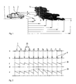
- a range finder 2 consisting of transmitter and receiver and operating according to the pulse transit time method is attached, which can be, for example, a laser range finder.
- This rangefinder is aligned with the road surface 3, which is divided into equidistant steps a to j on a corresponding panel, and can be pivoted in the joint 4 by angle ⁇ in elevation, either continuously or stepwise. The same movement can be carried out in many cases, mostly even more elegantly, by means of a scanning mirror, which is not shown here in the drawing.
- the range which corresponds approximately to the range of vision, is greater than the entire measuring distance j, so that the driver can drive in unhindered.
- the signal from point a reflects because the car is approaching the fog wall 5
- a plurality of range finders 2 can also be mounted in the front area of the car 1 one above the other and with different, but stepped inclination angles ⁇ to the road surface 3.
- several measuring beams are emitted at the same time, so that in the end the same information results for the driver. It is obvious that both variants shown only work if the course of the road in front of the vehicle is straight in the area of the measuring distance. The driver may therefore only sensibly operate the device if he believes that he is on a straight stretch of the road.
- a measurement of the relative speed between the car 1 with its range finder 2 and the target can also be combined with the visibility measurement described so far.
- all measurements aligned to the road surface 3 using the Doppler effect then show the vehicle speed.
- this obstacle determines or displays the visibility and the relative speed of one's own car with respect to this obstacle - provided there is sufficient visibility. This means that the relative speed of vehicles in front can also be determined in this way with the range finder in the absence of fog.
- the ten measuring points a to j of the road surface 3 can be assigned ten reception channels 11 to 21, the associated needle pulses 8 of which are delayed in time with respect to the transmission pulses 7 so that they are off 10, 20, 30 ... 100 m distance reflected transmission pulses coincide.
- the measuring beam of the transmitter containing the transmission signal is now deflected via a scanning mirror (not shown in the drawing) in such a way that it first hits the road surface 3 at a distance of 100 m and then comes closer and closer by tilting the mirror, the needle pulse is successively transmitted via the received pulses 7 'of the ten channels 11 to 21 are running, each channel reporting the arrival of its needle pulse. The otherwise necessary phase modulation of the needle pulse is not necessary here.
- Monitoring electronics now only need to determine which channel has received signals.
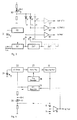
- the pulse generator 22 (FIG. 3) generates a voltage, so that the transmitter diode 31 emits the signal pulse 7 (FIG. 2) after optoelectronic conversion.
- a small part of the pulse-shaped driver voltage is decoupled and after passing through the delay elements 24 'to used as needle pulse 8 according to FIG. 2b.
- the delay times 25 (FIG. 2) are set in such a way that they correspond to the predetermined path of the signal pulses to be detected from the transmitting diode 31 to the destination, that is to say the roadway ceiling 3, and back again to the receiving diode 30.
- the device In order to determine the relative speed mentioned above, the device must be switched to another operating mode.
- the scanning mirror stands still in the position that corresponds to the furthest distance. Now only one of the ten reception channels 11 to 21 needs to be used.
- the pulse generator 22 can be used as a trigger for the monoflop stage 27, the time constant of which is varied by a modulation voltage of the modulation generator 28.
- the needle pulse is then obtained again from the trailing edge of the monoflop pulse.
- the area to be monitored can be set as required.
- the envelope of the signal contains the information about the relative speed sought, while in the second case it results from the distance and time measurement that has taken place.
- the scanning mirror can be replaced in the following way:
- any optical means for example a cylindrical lens
- the transmission and reception beam are expanded in the vertical direction in such a way that all ten measurement points a to j are detected.
- a chopper is arranged in front of or behind the optics, which modulates the transmit or receive beam in a simple manner such that a yes / no statement about possibly in the 100 Hz rhythm in all 10 channels (11-21) Obstacles are created.
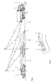
- the car 1 shown with solid lines runs at a certain distance behind the truck 1 '.
- the laser transmission and reception module 2 which operates according to the pulse transit time method, is fastened, the optical axis of which can be pivoted in a plane vertical to the direction of travel by means of an opto-mechanical or electro-optical element (not shown in the drawing).
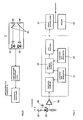
- the reflections occurring in positions a to n of the road surface 3 are made visually and / or acoustically recognizable to the driver in the interior of the car after corresponding optoelectronic conversion and signal processing on the display 32 (FIG. 7).
- the signal processing can include an expansion and averaging of the reflected signal over a series of successive laser pulses, as is understood by the term “sampling method”. In this respect, it is known prior art.
- Equation (1) when applied to FIG. 1 means: By forming the quotinet of equations (2) and (3) with constant output power P:
- the total readout time in the assumed example is 25.6 microseconds, which is well adapted to the maximum laser pulse repetition frequency.
- E.g. drives 5 from position a to position b and looking at the signals coming from position c, the change in the signal - apart from geometric factors - only results from the change in atmospheric attenuation, that is to say the reflection factor ⁇ has no influence on a change (more precisely: the quotient) of the signals (see Eq. 5).
- the latter depends, in particular with a flat angle of incidence and observation, essentially on the weather-related road condition, i.e. the dryness, wetness or a possible ice layer. In principle, this method also makes it possible to make a statement about the condition of the road surface that is important for a driver.
- the receiving module part is equipped with a polarization switch, so that separately reflected radiation can then be measured with a polarization axis parallel to the linearly polarized transmission beam and perpendicular to it.
- the degree of depolarization of the radiation is determined, which also depends on the condition of the road surface: A dry roadway causes a strong, wet or icy roadway a lower depolarization.
- the visibility can also be determined using the proposed measures if the radiation is reflected by the truck 1 'driving ahead (FIG. 5) or by other objects on or next to the carriageway 3. If the speed does not correspond to the range of vision, the driver is warned acoustically via the display 12 and / or if necessary.
- the measuring system of the rear vehicle 1 with the speed v 1 will give a warning if the relative speed to the vehicle 1 ', v 1 - v 2, exceeds a value dependent on the visibility.
- the system of vehicle 2 warns when the road - as shown - makes a sharp bend, the bend cannot be seen or cannot be seen immediately and at the same time the speed is too high.
- Obstacles can be identified here by the discontinuity of the distance indicated in FIG. 5 - car 1 is shown at two distances from the truck 1 ′ driving ahead: the system scans the measuring points a to n. In the case of an open road, the distance increases in a systematic manner, the exact course depending on changes in the road inclination and the pitch angle of the vehicle, but the general course is comparable. An obstacle interrupts this course and is recognized as such.
- the standard range of vision V n is a clearly defined variable.
- the actual visually relevant visibility depends on various environmental parameters, such as the ambient brightness or the brightness of the road surface. This can be determined in a simple manner by measuring the DC current on the line branch 39, 40 in FIG. 7 and used to calculate the real visibility.
Landscapes
- Physics & Mathematics (AREA)
- Engineering & Computer Science (AREA)
- Electromagnetism (AREA)
- Computer Networks & Wireless Communication (AREA)
- General Physics & Mathematics (AREA)
- Radar, Positioning & Navigation (AREA)
- Remote Sensing (AREA)
- Optical Radar Systems And Details Thereof (AREA)
- Measurement Of Optical Distance (AREA)
Applications Claiming Priority (4)
| Application Number | Priority Date | Filing Date | Title |
|---|---|---|---|
| DE4005919 | 1990-02-24 | ||
| DE4005919A DE4005919C2 (de) | 1990-02-24 | 1990-02-24 | Verfahren und Anordnung zum Ermitteln der Sichtweite für Autofahrer beim Auftreten von Nebel |
| DE4016973 | 1990-05-25 | ||
| DE4016973A DE4016973C1 (fr) | 1990-02-24 | 1990-05-25 |
Publications (2)
| Publication Number | Publication Date |
|---|---|
| EP0444402A2 true EP0444402A2 (fr) | 1991-09-04 |
| EP0444402A3 EP0444402A3 (en) | 1993-01-13 |
Family
ID=25890509
Family Applications (1)
| Application Number | Title | Priority Date | Filing Date |
|---|---|---|---|
| EP19910100316 Withdrawn EP0444402A3 (en) | 1990-02-24 | 1991-01-11 | Method and apparatus for indicating visibility in fog to drivers of motor vehicles |
Country Status (4)
| Country | Link |
|---|---|
| US (1) | US5118180A (fr) |
| EP (1) | EP0444402A3 (fr) |
| JP (1) | JPH04215089A (fr) |
| DE (1) | DE4016973C1 (fr) |
Cited By (3)
| Publication number | Priority date | Publication date | Assignee | Title |
|---|---|---|---|---|
| WO1994012893A1 (fr) * | 1992-11-20 | 1994-06-09 | Gec-Marconi Avionics (Holdings) Limited | Systeme aidant un vehicule a effectuer une marche arriere |
| EP0691534A1 (fr) * | 1994-07-06 | 1996-01-10 | Volkswagen Aktiengesellschaft | Procédé de détermination de la visibilité, en particulier pour le déplacement d'un véhicule |
| CN103180794A (zh) * | 2010-07-26 | 2013-06-26 | 联邦科学和工业研究组织 | 三维扫描束系统和方法 |
Families Citing this family (35)
| Publication number | Priority date | Publication date | Assignee | Title |
|---|---|---|---|---|
| DE4137551A1 (de) * | 1990-03-10 | 1993-03-11 | Daimler Benz Ag | Anordnung zur verbesserung der sicht, insbesondere in fahrzeugen |
| DE4106289A1 (de) * | 1991-02-28 | 1992-09-03 | Bayerische Motoren Werke Ag | Pruefverfahren fuer die sichtverhaeltnisse auf fahrbahnen und vorrichtung zur durchfuehrung des verfahrens |
| DE4124192A1 (de) * | 1991-07-20 | 1993-01-21 | Dornier Luftfahrt | Abstandsmessgeraet oder abstandswarngeraet |
| DE4233379C1 (de) * | 1992-10-05 | 1994-03-31 | Leica Ag Heerbrugg | Verfahren und Vorrichtung zur relativen Sichtweitenbestimmung |
| US5546188A (en) * | 1992-11-23 | 1996-08-13 | Schwartz Electro-Optics, Inc. | Intelligent vehicle highway system sensor and method |
| US5321490A (en) * | 1992-11-23 | 1994-06-14 | Schwartz Electro-Optics, Inc. | Active near-field object sensor and method employing object classification techniques |
| DE4301228C1 (de) * | 1993-01-19 | 1994-04-21 | Daimler Benz Ag | Verfahren zur Bestimmung der Sichtweite |
| US5354981A (en) * | 1993-07-14 | 1994-10-11 | Loral Fairchild Corporation | Switching photosensitive matrix device |
| DE4324308C1 (de) * | 1993-07-20 | 1994-12-22 | Bayerische Motoren Werke Ag | Verfahren zum Bestimmen der Sichtweite bei dichtem Nebel sowie Sichtweitensensor |
| JP3294726B2 (ja) * | 1994-12-20 | 2002-06-24 | 本田技研工業株式会社 | レーダ装置 |
| DE19931825A1 (de) * | 1999-07-08 | 2001-01-25 | Bosch Gmbh Robert | Vorrichtung zur Sichtweitenmessung |
| DE19955249A1 (de) * | 1999-11-17 | 2001-05-23 | Bosch Gmbh Robert | Verfahren zur Sichtweitenmessung |
| US6563432B1 (en) * | 2001-01-12 | 2003-05-13 | Safegate International Ab | Aircraft docking system and method with automatic checking of apron and detection of fog or snow |
| WO2004092395A2 (fr) * | 2003-04-08 | 2004-10-28 | Baylor College Of Medicine | Modulateurs de la stabilite de telomeres |
| JP3994941B2 (ja) * | 2003-07-22 | 2007-10-24 | オムロン株式会社 | 車両用レーダ装置 |
| DE10337006A1 (de) * | 2003-08-12 | 2005-03-10 | Continental Ag | Verfahren und Vorrichtung zur Verbesserung des Fahrkomforts von Kraftfahrzeugen |
| DE102004045329A1 (de) * | 2004-09-16 | 2006-04-06 | Siemens Ag | Verkehrsmittel mit Nachtsichtsystem |
| JP4725391B2 (ja) * | 2006-03-29 | 2011-07-13 | 株式会社デンソー | 車両用視程測定装置、及び運転支援装置 |
| JP4940458B2 (ja) * | 2007-08-10 | 2012-05-30 | 本田技研工業株式会社 | 物体検出装置 |
| US8087589B2 (en) * | 2007-11-02 | 2012-01-03 | Intermec Ip Corp. | Laser barcode scanner employing heterodyning techniques |
| US8010316B2 (en) | 2008-12-11 | 2011-08-30 | Intermec Ip Corp. | System and method for laser range-finding |
| CN101886928A (zh) * | 2009-05-14 | 2010-11-17 | 深圳富泰宏精密工业有限公司 | 具有导盲功能的便携式电子装置 |
| DE102009046597A1 (de) | 2009-11-11 | 2011-05-12 | Robert Bosch Gmbh | Verfahren und Einrichtung für die Störungsverminderung bei einem Lidarsystem |
| EP2722684B1 (fr) * | 2012-10-19 | 2019-08-28 | Sick Ag | Lecteur laser |
| US9239959B1 (en) | 2013-04-08 | 2016-01-19 | Lockheed Martin Corporation | Multi-resolution, wide field-of-view, unmanned ground vehicle navigation sensor |
| SE537280C2 (sv) * | 2013-07-18 | 2015-03-24 | Scania Cv Ab | Tolkning av mätpunkt detekterad av en optisk sensor |
| CN104966298A (zh) * | 2015-06-17 | 2015-10-07 | 南京大学 | 一种基于微光云图数据的夜间低云大雾监测方法 |
| JP2016001182A (ja) * | 2015-07-21 | 2016-01-07 | コモンウェルス サイエンティフィック アンド インダストリアル リサーチ オーガナイゼーション | 3次元走査ビーム・システムおよび方法 |
| DE102015112103B4 (de) | 2015-07-24 | 2025-09-18 | Preh Gmbh | Detektionsvorrichtung zur Nebelerkennung für ein Kraftfahrzeug |
| JP6868570B2 (ja) | 2015-12-21 | 2021-05-12 | 株式会社小糸製作所 | 車両用画像取得装置、制御装置、車両用画像取得装置または制御装置を備えた車両および車両用画像取得方法 |
| CN108431629B (zh) | 2015-12-21 | 2022-07-08 | 株式会社小糸制作所 | 车辆用图像获取装置、控制装置、包括了车辆用图像获取装置或控制装置的车辆和车辆用图像获取方法 |
| EP3396411A4 (fr) | 2015-12-21 | 2019-08-21 | Koito Manufacturing Co., Ltd. | Dispositif d'acquisition d'image pour véhicules, et véhicule pourvu dudit dispositif |
| US11194023B2 (en) | 2015-12-21 | 2021-12-07 | Koito Manufacturing Co., Ltd. | Image acquiring apparatus for vehicle, control device, vehicle having image acquiring apparatus for vehicle or control device, and image acquiring method for vehicle |
| US20200081102A1 (en) * | 2018-09-10 | 2020-03-12 | Robotic Research, Llc | Ladar for military and harsh environment use |
| CN115616530B (zh) * | 2022-12-16 | 2023-03-31 | 青岛镭测创芯科技有限公司 | 一种激光雷达光学扫描装置 |
Family Cites Families (13)
| Publication number | Priority date | Publication date | Assignee | Title |
|---|---|---|---|---|
| SE358478B (fr) * | 1970-11-16 | 1973-07-30 | Asea Ab | |
| DE2223230C3 (de) * | 1972-05-12 | 1975-04-30 | Eltro Gmbh Gesellschaft Fuer Strahlungstechnik, 6900 Heidelberg | Verfahren zur Überwachung der Durchlässigkeit der Atmosphäre |
| ZA801538B (en) * | 1979-03-19 | 1981-04-29 | United Kingdom Government | Method and apparatus for estimating slant visibility in fog |
| JPS5876784A (ja) * | 1981-10-31 | 1983-05-09 | Nissan Motor Co Ltd | 車両用光パルスレ−ダ装置 |
| JPS58155379A (ja) * | 1982-03-12 | 1983-09-16 | Kimio Yamawaki | 光ドツプラ−レ−ダ− |
| DE3215845C1 (de) * | 1982-04-28 | 1983-11-17 | Eltro GmbH, Gesellschaft für Strahlungstechnik, 6900 Heidelberg | Abstandssensor fuer einen Geschosszuender |
| JPS5917182A (ja) * | 1982-07-20 | 1984-01-28 | Nissan Motor Co Ltd | 路面状況検知用光レ−ダ装置 |
| CA1235773A (fr) * | 1983-12-23 | 1988-04-26 | Shigeto Nakayama | Detecteur d'etat d'une chaussee |
| JPS6123985A (ja) * | 1984-07-13 | 1986-02-01 | Nissan Motor Co Ltd | 車間距離検出装置 |
| JPS62231189A (ja) * | 1986-04-01 | 1987-10-09 | Nissan Motor Co Ltd | 速度算出装置 |
| DE3635396A1 (de) * | 1986-10-17 | 1988-04-28 | Bayerische Motoren Werke Ag | Vorrichtung zum erkennen von hindernissen fuer kraftfahrzeuge |
| DE3735267C3 (de) * | 1987-10-17 | 1996-03-21 | Telefunken Microelectron | Vorrichtung zur Sichtweitenmessung |
| DE3738221A1 (de) * | 1987-11-11 | 1989-06-08 | Bayerische Motoren Werke Ag | Verfahren und einrichtung zum erkennen des zustandes einer strasse |
-
1990
- 1990-05-25 DE DE4016973A patent/DE4016973C1/de not_active Expired - Fee Related
-
1991
- 1991-01-11 EP EP19910100316 patent/EP0444402A3/de not_active Withdrawn
- 1991-02-22 JP JP3028705A patent/JPH04215089A/ja active Pending
- 1991-02-22 US US07/660,440 patent/US5118180A/en not_active Expired - Fee Related
Cited By (5)
| Publication number | Priority date | Publication date | Assignee | Title |
|---|---|---|---|---|
| WO1994012893A1 (fr) * | 1992-11-20 | 1994-06-09 | Gec-Marconi Avionics (Holdings) Limited | Systeme aidant un vehicule a effectuer une marche arriere |
| EP0691534A1 (fr) * | 1994-07-06 | 1996-01-10 | Volkswagen Aktiengesellschaft | Procédé de détermination de la visibilité, en particulier pour le déplacement d'un véhicule |
| CN103180794A (zh) * | 2010-07-26 | 2013-06-26 | 联邦科学和工业研究组织 | 三维扫描束系统和方法 |
| US9146315B2 (en) | 2010-07-26 | 2015-09-29 | Commonwealth Scientific And Industrial Research Organisation | Three dimensional scanning beam system and method |
| CN103180794B (zh) * | 2010-07-26 | 2017-02-15 | 联邦科学和工业研究组织 | 三维扫描束系统和方法 |
Also Published As
| Publication number | Publication date |
|---|---|
| JPH04215089A (ja) | 1992-08-05 |
| EP0444402A3 (en) | 1993-01-13 |
| US5118180A (en) | 1992-06-02 |
| DE4016973C1 (fr) | 1991-06-13 |
Similar Documents
| Publication | Publication Date | Title |
|---|---|---|
| EP0444402A2 (fr) | Méthode et appareil pour indiquer aux automobilistes la limite de visibilité dans le brouillard | |
| DE19531632B4 (de) | Entfernungsmeßgerät | |
| EP0396865B1 (fr) | Radar optique | |
| EP2191298B1 (fr) | Procédé permettant de déterminer une distance au moyen d'un capteur d'image optoélectronique | |
| EP0785883B1 (fr) | Detecteur de distance de visibilite et de presence de pluie | |
| DE4040894C1 (en) | Motor vehicle parking aid using pulsed laser - evaluates signal reflected from obstacle and received by semiconductor diode at rear corner of vehicle | |
| EP2800982A1 (fr) | Procédé et dispositif pour la mesure de vitesse indépendante des roues, pour un véhicule | |
| DE3827729A1 (de) | Kollisionswarneinrichtung fuer kraftfahrzeuge | |
| DE4005919C1 (en) | Ascertaining range of vision of car driver in fog - using range finder transmitting signals and receiving those reflected from road surface not covered by fog | |
| DE2229887A1 (de) | Verfahren zum messen des abstands von und der geschwindigkeitskomponente eines objektes senkrecht zu einer bezugslinie | |
| DE102019127667A1 (de) | Entfernungsmessender optoelektronischer Sensor und Verfahren zur Erfassung eines Zielobjekts | |
| DE102015217912A1 (de) | Verfahren zur Laufzeitkalibrierung eines Lidarsensors | |
| EP0814348A2 (fr) | Procédé pour mesurer la distance entre un véhicule et un objet | |
| EP0811855A2 (fr) | Système de capteurs pour le contrÔle automatique de la position relative | |
| EP2221640B1 (fr) | Procédé de mesure de la vitesse d'un véhicule et affectation visible dans une documentation | |
| EP0139707A1 (fr) | Dispositif pour detecter d'autres vehicules dans le champ de vision arriere d'un vehicule | |
| DE102004031024B4 (de) | Optischer Sensor | |
| EP3591424A1 (fr) | Caméra d'évaluation du temps de propagation de la lumière 3d et procédé de détection de données d'image tridimensionnelles | |
| DE10138531A1 (de) | Verfahren und Vorrichtung zur Aufnahme eines dreidimensionalen Abstandsbildes | |
| DE102005003191A1 (de) | Vorrichtung und Verfahren zur Umfelderfassung eines bewegbaren Objektes | |
| EP4252026B1 (fr) | Procédé de fonctionnement d'un dispositif de détection pour déterminer des variables de distance avec réglage de température, dispositif de détection correspondant et véhicule comportant au moins un dispositif de détection de ce type | |
| DE3225474C2 (de) | Verfahren zur Zielerkennung | |
| EP1684094A2 (fr) | Procédé de triangulation optique pour determiner la distance pour les applications des véhicules automobiles | |
| DE102023117446B3 (de) | Optisches System | |
| DE19910501A1 (de) | Verfahren und Vorrichtung zur Bestimmung einer Geschwindigkeit eines Kraftfahrzeuges |
Legal Events
| Date | Code | Title | Description |
|---|---|---|---|
| PUAI | Public reference made under article 153(3) epc to a published international application that has entered the european phase |
Free format text: ORIGINAL CODE: 0009012 |
|
| AK | Designated contracting states |
Kind code of ref document: A2 Designated state(s): DE FR GB IT SE |
|
| PUAL | Search report despatched |
Free format text: ORIGINAL CODE: 0009013 |
|
| AK | Designated contracting states |
Kind code of ref document: A3 Designated state(s): DE FR GB IT SE |
|
| STAA | Information on the status of an ep patent application or granted ep patent |
Free format text: STATUS: THE APPLICATION IS DEEMED TO BE WITHDRAWN |
|
| 18D | Application deemed to be withdrawn |
Effective date: 19930910 |