EP0444443B1 - Dispositif de lyophilisation - Google Patents
Dispositif de lyophilisation Download PDFInfo
- Publication number
- EP0444443B1 EP0444443B1 EP91101553A EP91101553A EP0444443B1 EP 0444443 B1 EP0444443 B1 EP 0444443B1 EP 91101553 A EP91101553 A EP 91101553A EP 91101553 A EP91101553 A EP 91101553A EP 0444443 B1 EP0444443 B1 EP 0444443B1
- Authority
- EP
- European Patent Office
- Prior art keywords
- fact
- disc
- accordance
- freeze
- dish
- Prior art date
- Legal status (The legal status is an assumption and is not a legal conclusion. Google has not performed a legal analysis and makes no representation as to the accuracy of the status listed.)
- Expired - Lifetime
Links
Images
Classifications
-
- F—MECHANICAL ENGINEERING; LIGHTING; HEATING; WEAPONS; BLASTING
- F26—DRYING
- F26B—DRYING SOLID MATERIALS OR OBJECTS BY REMOVING LIQUID THEREFROM
- F26B5/00—Drying solid materials or objects by processes not involving the application of heat
- F26B5/04—Drying solid materials or objects by processes not involving the application of heat by evaporation or sublimation of moisture under reduced pressure, e.g. in a vacuum
- F26B5/06—Drying solid materials or objects by processes not involving the application of heat by evaporation or sublimation of moisture under reduced pressure, e.g. in a vacuum the process involving freezing
-
- Y—GENERAL TAGGING OF NEW TECHNOLOGICAL DEVELOPMENTS; GENERAL TAGGING OF CROSS-SECTIONAL TECHNOLOGIES SPANNING OVER SEVERAL SECTIONS OF THE IPC; TECHNICAL SUBJECTS COVERED BY FORMER USPC CROSS-REFERENCE ART COLLECTIONS [XRACs] AND DIGESTS
- Y10—TECHNICAL SUBJECTS COVERED BY FORMER USPC
- Y10T—TECHNICAL SUBJECTS COVERED BY FORMER US CLASSIFICATION
- Y10T137/00—Fluid handling
- Y10T137/8593—Systems
- Y10T137/86493—Multi-way valve unit
- Y10T137/86718—Dividing into parallel flow paths with recombining
- Y10T137/86743—Rotary
Definitions
- the invention relates to a freeze-drying device with a freeze-drying chamber, with a condenser chamber and with an intermediate plate which is located between the freeze-drying chamber and the condenser chamber and is equipped with a lockable passage for connecting and separating the two chambers.
- a freeze dryer of this type is known from US-A-30 77 036.
- the freeze-drying chamber of this device has shelves on which the product is located while the drying process is being carried out.
- a condenser with an evacuation connection is provided to generate the required vacuum and to accumulate the vapors generated during the drying process.
- DE-B-12 76 554 also belongs to the prior art. It discloses a freeze-drying device with a freeze-drying chamber, a condenser and an intermediate plate which is equipped with openings into which the Condenser forming pipes open. The openings in the intermediate plate cannot be locked.
- the present invention has for its object to provide a freeze-drying device of the type mentioned, which do not have the disadvantages described in the prior art according to US-A-30 77 036.
- the plate and disk have several (for example four) openings lying on a circle concentric to the axis of rotation. A particularly uniform flow through the passage cross-section in the intermediate plate is thereby achieved.
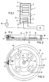
- the freeze-drying device 1 shown in FIG. 1 has the freeze-drying chamber 2 and the condenser chamber 3. Both are cylindrical and one above the other.
- the intermediate plate 4 simultaneously forms the lid of the condenser chamber 3 and the bottom of the freeze-drying chamber 2.
- the intermediate plate 4 is not shown in detail in FIG. 1 Lockable openings equipped, which allow the chamber 2 and 3 to be connected and separated.
- the freeze-drying chamber 2 there is a frame 5 with the setting plates 6.
- a cylindrical hood is provided as the chamber wall 7, which is supported on the intermediate plate 4 and suitably consists of acrylic glass.
- the capacitor chamber 3 is formed by the intermediate plate 4, the base plate 8 and the cylindrical housing section 9, which preferably also consists of acrylic glass.
- the condenser 11 is located within the condenser chamber 3.
- the base plate 8 is supported on a housing, not shown in detail, in which - as indicated schematically - there is a refrigerator 12 for supplying the condenser 11 and a vacuum pump 13 for evacuating the condenser chamber 3 .
- FIGS. 2 and 3 show that the intermediate plate 4 comprises a plate 15 and a ring 16 of the same diameter placed thereon in a vacuum-tight manner.
- the center of the plate 15 is equipped with a concentric extension 17 which forms a hub for an annular disk 18.
- the disc 18 is rotatable about the axis 19.
- Both the plate 15 and the disc 18 are each equipped with four circular openings 21 and 22 (Figure 3). These openings 21, 22 lie with respect to the axis 19 on a circle 23 (shown in broken lines). The diameter of the openings 21, 22 is smaller than their distance on the circle 23, so that a valve function can be achieved by rotating the disk 18.
- the passage cross section formed by the openings 21, 22 is continuously adjustable between the complete opening (concentric position of the openings 21, 22 with respect to one another) and a tight seal (non-overlapping position of the openings 21, 22).
- a carrier 27 for a magnet 28 is fastened to the disk 18.
- the ring 16 is equipped on part of its circumference with a guide groove 29, in which a metallic or magnetic counterpart 31 is guided to the magnet 28. Moving the counterpart 31 in the guide groove causes the plate 18 to rotate.
Landscapes
- Engineering & Computer Science (AREA)
- Health & Medical Sciences (AREA)
- Life Sciences & Earth Sciences (AREA)
- Molecular Biology (AREA)
- Mechanical Engineering (AREA)
- General Engineering & Computer Science (AREA)
- Drying Of Solid Materials (AREA)
Claims (8)
- Installation de lyophilisation avec chambre de lyophilisation (2), un condenseur (3) et une plaque intermédiaire(4), laquelle se trouve entre la chambre de lyophilisation et le condenseur et qui est équipée d'un passage pouvant être fermé pour relier ou séparer les deux enceintes (2,3), caractérisée en ce que la plaque intermédiaire (4) est constituée d'une rondelle fixe (15) et d'un disque (18) pouvant tourner autour de l'axe (19) de la rondelle (15), que pour former le passage pouvant être verrouillé, la rondelle (15) et le disque (18) sont munis d'orifices (21, 22) se trouvant chacun à distance de l'axe de rotation, lesquels orifices (21, 22) sont conçus de telle sorte qu'ils puissent être réglables par un mouvement rotatif dans une situation de superposition, de non superposition et dans des positions intermédiaires.
- Installation selon la revendication 1, caractérisée en ce que la rondelle (15) et le disque (18) présentent plusieurs, de préférence quatre, orifices (21 et 22) se trouvant sur un cercle (23) concentrique à l'axe de rotation.
- Installation selon la revendication 1 ou 2, caractérisée en ce que les orifices (21 et 22) sont en forme de cercle, que leur taille est identique et que leur diamètre est inférieur à leur distance sur le cercle concentrique (23).
- Installation selon l'une des revendications 1 à 3, caractérisée en ce que la rondelle (15) fixe est équipée d'un rebord (17) central et que le disque (18) a la forme d'un cercle, de telle sorte qu'il s'adapte sur le rebord central (17).
- Installation selon la revendication 4, caractérisée en ce qu'au centre de la rondelle (15), un positionnement (25) est prévu pour la butée d'un dispositif de rotation.
- Installation selon la revendication 4 ou 5, caractérisée en ce que des aimants auxiliaires (28, 31) sont prévus pour permettre une transmission pour faire tourner le disque (18) sans traversée.
- Installation selon la revendication 6, caractérisée en ce que le disque (18) est équipé d'un support (27) d'aimant (28).
- Installation selon la revendication 7, caractérisée en ce qu'il existe un anneau (16) entourant la rondelle, anneau équipé d'une rainure extérieure, dans laquelle un pendant (31) est déplacé vers l'aimant (28).
Applications Claiming Priority (2)
| Application Number | Priority Date | Filing Date | Title |
|---|---|---|---|
| DE4006015A DE4006015A1 (de) | 1990-02-26 | 1990-02-26 | Gefriertrocknungseinrichtung |
| DE4006015 | 1990-02-26 |
Publications (2)
| Publication Number | Publication Date |
|---|---|
| EP0444443A1 EP0444443A1 (fr) | 1991-09-04 |
| EP0444443B1 true EP0444443B1 (fr) | 1994-07-06 |
Family
ID=6400989
Family Applications (1)
| Application Number | Title | Priority Date | Filing Date |
|---|---|---|---|
| EP91101553A Expired - Lifetime EP0444443B1 (fr) | 1990-02-26 | 1991-02-06 | Dispositif de lyophilisation |
Country Status (4)
| Country | Link |
|---|---|
| US (1) | US5131170A (fr) |
| EP (1) | EP0444443B1 (fr) |
| JP (1) | JPH05231767A (fr) |
| DE (2) | DE4006015A1 (fr) |
Families Citing this family (10)
| Publication number | Priority date | Publication date | Assignee | Title |
|---|---|---|---|---|
| AT1399U1 (de) | 1995-11-29 | 1997-04-25 | Immuno Ag | Verfahren und einrichtung zum lyophilisieren |
| FR2814089B1 (fr) | 2000-09-21 | 2003-07-04 | Ethypharm Lab Prod Ethiques | Procede pour isoler et secher des microparticules (microspheres ou microcapsules) initialement dispersees ou suspendues en phase liquide |
| US6945264B1 (en) | 2004-07-09 | 2005-09-20 | Zurn Industries, Inc. | Flow control valve and method for using the same |
| US7073775B2 (en) * | 2004-09-13 | 2006-07-11 | Cameron International Corporation | Rotating check valve for compression equipment |
| CN100357687C (zh) * | 2005-04-01 | 2007-12-26 | 南通冷冻设备有限公司 | 一种真空冷冻干燥装置 |
| US9739395B2 (en) * | 2014-01-09 | 2017-08-22 | Dresser-Rand Company | Grid valve apparatus |
| EP3303958B1 (fr) * | 2015-06-01 | 2019-10-09 | IMA Life North America Inc. | Lyophilisation en vrac utilisant la congélation par pulvérisation et le séchage avec agitation et chauffage |
| CN105222576A (zh) * | 2015-10-27 | 2016-01-06 | 江苏楷益智能科技有限公司 | 冷冻干燥装置的干燥箱与隔板连接机构 |
| CN107588601A (zh) * | 2017-09-19 | 2018-01-16 | 上海东富龙科技股份有限公司 | 液体直接灌装无托盘冻干机 |
| CN109737713B (zh) * | 2018-12-12 | 2020-09-22 | 泰州市扬帆车件有限公司 | 一种磁动自旋转烤架 |
Family Cites Families (13)
| Publication number | Priority date | Publication date | Assignee | Title |
|---|---|---|---|---|
| US3077036A (en) * | 1959-01-10 | 1963-02-12 | Leybold Hochvakuum Anlagen | Temperature responsive freeze drying method and apparatus |
| DE1160290B (de) * | 1959-10-30 | 1963-12-27 | Schwermaschb Iakarl Liebknecht | Sammelstueck fuer den wahlweisen Anschluss der Ausblaseleitungen mehrerer Zellstoffkocher an einem gemeinsamen Ausblasebehaelter |
| DE1185544B (de) * | 1963-05-10 | 1965-01-14 | Leybold Hockvakuum Anlagen G M | Mit gasfoermigem Kuehlmittel betriebene Gefriertrocknungskammer |
| US3271874A (en) * | 1965-01-28 | 1966-09-13 | Oppenheimer Suzanne Bohnen | Infra-red sublimation method and apparatus for freeze drying techniques |
| DK117688B (da) * | 1965-03-18 | 1970-05-19 | Atlas As | Apparat til frysetørring af vandholdige produkter under vakuum. |
| DE1276554B (de) * | 1965-08-04 | 1968-08-29 | Paul Stein Dipl Ing Dr | Gefriertrocknungsanlage fuer biologische Praeparate |
| DK126720B (da) * | 1968-05-11 | 1973-08-13 | Leybold Heraeus Verwaltung | Apparat til kontinuerlig frysettørring. |
| DK137287B (da) * | 1970-08-25 | 1978-02-13 | Atlas As | Frysetørringsapparat. |
| US3997978A (en) * | 1975-09-08 | 1976-12-21 | Stuckey Alfred R | Rope conditioning apparatus |
| US4395019A (en) * | 1981-04-24 | 1983-07-26 | Mobil Oil Corporation | Seal for wear resistant inserts |
| AT374206B (de) * | 1982-11-15 | 1984-03-26 | Hirsch Kurt | Verfahren und vorrichtung zum vorschaeumen von kunststoffen |
| US4516606A (en) * | 1983-02-16 | 1985-05-14 | Exxon Research And Engineering Co. | Variable orifice valve assembly |
| US4776104A (en) * | 1987-04-27 | 1988-10-11 | Kuboyama Nobuyoshi | Balanced extraction system |
-
1990
- 1990-02-26 DE DE4006015A patent/DE4006015A1/de not_active Withdrawn
-
1991
- 1991-02-06 EP EP91101553A patent/EP0444443B1/fr not_active Expired - Lifetime
- 1991-02-06 DE DE59102090T patent/DE59102090D1/de not_active Expired - Fee Related
- 1991-02-22 US US07/659,586 patent/US5131170A/en not_active Expired - Fee Related
- 1991-02-25 JP JP3030133A patent/JPH05231767A/ja active Pending
Also Published As
| Publication number | Publication date |
|---|---|
| DE4006015A1 (de) | 1991-09-05 |
| JPH05231767A (ja) | 1993-09-07 |
| EP0444443A1 (fr) | 1991-09-04 |
| US5131170A (en) | 1992-07-21 |
| DE59102090D1 (de) | 1994-08-11 |
Similar Documents
| Publication | Publication Date | Title |
|---|---|---|
| DE68908159T2 (de) | Zentrifugalabscheider. | |
| DE2454544C3 (de) | Vakuumbeschichtungsanlage | |
| DE2611307C2 (fr) | ||
| CH657541A5 (de) | Verfahren und einrichtung zum trennen magnetischer von unmagnetischen teilchen. | |
| EP0444443A1 (fr) | Dispositif de lyophilisation | |
| DE4232869A1 (de) | Supraleitende lagereinheit und verfahren zu ihrem betrieb | |
| DE2606408A1 (de) | Starkfeldmagnetscheider zur nassaufbereitung magnetisierbarer feststoffteilchen | |
| EP2153515A2 (fr) | Dispositif avec un agencement d'aimants | |
| WO2010031616A1 (fr) | Dispositif de séparation de particules ferromagnétiques d'une suspension | |
| DE3738223A1 (de) | Verfahren und vorrichtung zur energieanreicherung von wasser, waessrigen loesungen oder sonstigen fluessigkeiten oder schmelzen | |
| DE1926744A1 (de) | Beschleunigungsmesser | |
| DE3827252C2 (fr) | ||
| CH622720A5 (fr) | ||
| DE19626999C1 (de) | Hochgradienten-Magnetabscheider | |
| CH660695A5 (de) | Doppel-schubzentrifuge. | |
| DE102010031245A1 (de) | Substratbehandlungseinrichtung | |
| DE69022489T2 (de) | Verfahren zum Steuern einer Drucksiebvorrichtung und Drucksiebvorrichtung. | |
| AT518730B1 (de) | Vorrichtung zum Trennen von Teilchen unterschiedlicher Leitfähigkeit | |
| DE3723729A1 (de) | Wellendichtung, insbesondere fuer wellen von gasgekuehlten generatoren | |
| DE916617C (de) | Vorrichtung zum Abscheiden fester, in einem Gasstrom enthaltener Bestandteile | |
| DE69302247T2 (de) | Verfahren und vorrichtung zur trennung einer suspension, vorzugsweise eine fasersuspension | |
| EP0336346B1 (fr) | Dispositif de traitement électromagnétique des liquides, spécialement de l'eau | |
| DE2506638A1 (de) | Zerstaeubungstrockner | |
| DE2903522A1 (de) | Mehrstufige reinigungsanlage | |
| DE1432853A1 (de) | Verfahren und Vorrichtung zur Trennung von Stoffen durch Gyrofugation |
Legal Events
| Date | Code | Title | Description |
|---|---|---|---|
| PUAI | Public reference made under article 153(3) epc to a published international application that has entered the european phase |
Free format text: ORIGINAL CODE: 0009012 |
|
| AK | Designated contracting states |
Kind code of ref document: A1 Designated state(s): BE DE FR GB IT NL |
|
| 17P | Request for examination filed |
Effective date: 19920224 |
|
| 17Q | First examination report despatched |
Effective date: 19920703 |
|
| GRAA | (expected) grant |
Free format text: ORIGINAL CODE: 0009210 |
|
| RAP1 | Party data changed (applicant data changed or rights of an application transferred) |
Owner name: AMSCO FINN-AQUA GMBH |
|
| AK | Designated contracting states |
Kind code of ref document: B1 Designated state(s): BE DE FR GB IT NL |
|
| REF | Corresponds to: |
Ref document number: 59102090 Country of ref document: DE Date of ref document: 19940811 |
|
| ITF | It: translation for a ep patent filed | ||
| GBT | Gb: translation of ep patent filed (gb section 77(6)(a)/1977) |
Effective date: 19941013 |
|
| ET | Fr: translation filed | ||
| PGFP | Annual fee paid to national office [announced via postgrant information from national office to epo] |
Ref country code: BE Payment date: 19950104 Year of fee payment: 5 |
|
| PGFP | Annual fee paid to national office [announced via postgrant information from national office to epo] |
Ref country code: GB Payment date: 19950201 Year of fee payment: 5 |
|
| PGFP | Annual fee paid to national office [announced via postgrant information from national office to epo] |
Ref country code: NL Payment date: 19950228 Year of fee payment: 5 |
|
| PLBE | No opposition filed within time limit |
Free format text: ORIGINAL CODE: 0009261 |
|
| STAA | Information on the status of an ep patent application or granted ep patent |
Free format text: STATUS: NO OPPOSITION FILED WITHIN TIME LIMIT |
|
| 26N | No opposition filed | ||
| PG25 | Lapsed in a contracting state [announced via postgrant information from national office to epo] |
Ref country code: GB Effective date: 19960206 |
|
| PG25 | Lapsed in a contracting state [announced via postgrant information from national office to epo] |
Ref country code: BE Effective date: 19960228 |
|
| BERE | Be: lapsed |
Owner name: AMSCO FINN-AQUA G.M.B.H. Effective date: 19960228 |
|
| PG25 | Lapsed in a contracting state [announced via postgrant information from national office to epo] |
Ref country code: NL Effective date: 19960901 |
|
| GBPC | Gb: european patent ceased through non-payment of renewal fee |
Effective date: 19960206 |
|
| NLV4 | Nl: lapsed or anulled due to non-payment of the annual fee |
Effective date: 19960901 |
|
| PG25 | Lapsed in a contracting state [announced via postgrant information from national office to epo] |
Ref country code: IT Free format text: LAPSE BECAUSE OF NON-PAYMENT OF DUE FEES;WARNING: LAPSES OF ITALIAN PATENTS WITH EFFECTIVE DATE BEFORE 2007 MAY HAVE OCCURRED AT ANY TIME BEFORE 2007. THE CORRECT EFFECTIVE DATE MAY BE DIFFERENT FROM THE ONE RECORDED. Effective date: 20050206 |
|
| PGFP | Annual fee paid to national office [announced via postgrant information from national office to epo] |
Ref country code: FR Payment date: 20050217 Year of fee payment: 15 |
|
| PGFP | Annual fee paid to national office [announced via postgrant information from national office to epo] |
Ref country code: DE Payment date: 20050331 Year of fee payment: 15 |
|
| PG25 | Lapsed in a contracting state [announced via postgrant information from national office to epo] |
Ref country code: DE Free format text: LAPSE BECAUSE OF NON-PAYMENT OF DUE FEES Effective date: 20060901 |
|
| REG | Reference to a national code |
Ref country code: FR Ref legal event code: ST Effective date: 20061031 |
|
| PG25 | Lapsed in a contracting state [announced via postgrant information from national office to epo] |
Ref country code: FR Free format text: LAPSE BECAUSE OF NON-PAYMENT OF DUE FEES Effective date: 20060228 |