EP0444507A2 - Diverter in a rotary printing press - Google Patents
Diverter in a rotary printing press Download PDFInfo
- Publication number
- EP0444507A2 EP0444507A2 EP91102400A EP91102400A EP0444507A2 EP 0444507 A2 EP0444507 A2 EP 0444507A2 EP 91102400 A EP91102400 A EP 91102400A EP 91102400 A EP91102400 A EP 91102400A EP 0444507 A2 EP0444507 A2 EP 0444507A2
- Authority
- EP
- European Patent Office
- Prior art keywords
- switch
- segment
- signatures
- block
- switch segment
- Prior art date
- Legal status (The legal status is an assumption and is not a legal conclusion. Google has not performed a legal analysis and makes no representation as to the accuracy of the status listed.)
- Granted
Links
- 230000001154 acute effect Effects 0.000 claims description 3
- 238000010276 construction Methods 0.000 description 2
- 241000792859 Enema Species 0.000 description 1
- 239000000654 additive Substances 0.000 description 1
- 239000007920 enema Substances 0.000 description 1
- 229940095399 enema Drugs 0.000 description 1
- 239000000463 material Substances 0.000 description 1
Images


Classifications
-
- B—PERFORMING OPERATIONS; TRANSPORTING
- B65—CONVEYING; PACKING; STORING; HANDLING THIN OR FILAMENTARY MATERIAL
- B65H—HANDLING THIN OR FILAMENTARY MATERIAL, e.g. SHEETS, WEBS, CABLES
- B65H29/00—Delivering or advancing articles from machines; Advancing articles to or into piles
- B65H29/58—Article switches or diverters
-
- B—PERFORMING OPERATIONS; TRANSPORTING
- B65—CONVEYING; PACKING; STORING; HANDLING THIN OR FILAMENTARY MATERIAL
- B65H—HANDLING THIN OR FILAMENTARY MATERIAL, e.g. SHEETS, WEBS, CABLES
- B65H2404/00—Parts for transporting or guiding the handled material
- B65H2404/20—Belts
- B65H2404/26—Particular arrangement of belt, or belts
- B65H2404/261—Arrangement of belts, or belt(s) / roller(s) facing each other for forming a transport nip
-
- B—PERFORMING OPERATIONS; TRANSPORTING
- B65—CONVEYING; PACKING; STORING; HANDLING THIN OR FILAMENTARY MATERIAL
- B65H—HANDLING THIN OR FILAMENTARY MATERIAL, e.g. SHEETS, WEBS, CABLES
- B65H2701/00—Handled material; Storage means
- B65H2701/10—Handled articles or webs
- B65H2701/19—Specific article or web
- B65H2701/1932—Signatures, folded printed matter, newspapers or parts thereof and books
Definitions
- the invention relates to a controllable switch in a paper transport device of a web-fed rotary printing press.
- Controllable characters in a paper transport direction of a web-fed rotary printing press have become known from DE-PS 6 78 472.
- DE-OS 22 33 750 shows a switch controllable in time in the output of a folder of a web-fed rotary printing press.
- This publication also shows a typical tape transport system that shows how printed, folded signatures are transported between tapes from one place to a second.
- the switch segments used up to now are characterized in that the signatures to be diverted run up against a flat, relatively thin tip of the switch segment and quickly weaken this tip by material removal.
- the invention has for its object to provide a switch segment as part of a switch in a signature transport device of a web-fed rotary printing press, in particular, a folder with which a long service life with respect to wear can be achieved even at high production speeds.
- the advantages which can be achieved with the invention consist in particular in that, in addition to avoiding the above-mentioned disadvantages of the prior art, the point of impact of the signatures does not lie on the legs of the thin, flat-drawn tip of the switch segment.
- the point of application of force for controlling the switch segment does not have to be in the end opposite the tip of the switch segment, so a smaller drive torque is necessary.
- the turnout segment can be of shorter construction compared to flat-drawn turnout segments, so that the distance over which signatures without double tape guidance be promoted, becomes shorter.
- the signature inlet between the conveyor belt and the switch segment can initially be designed in a funnel shape.
- the switch segments since they are made thicker, can be made comb-like at one or both ends, so that the conveyor belt and / or guide rollers can run in the space between two prongs of the switch segment. This ensures that the upper and lower conveyor belts can run closer together in the switch segment area. This also enables a more compact construction of the entire turnout and thus short deflection paths without double conveyor belt guidance.
- the transport of signatures 1 in folders by means of synchronously driven, several upper and lower conveyor belts 2; B. by DE-PS 27 23 358.
- the signatures 1 are "clamped” along a first conveyor path 5 between the upper and lower conveyor belts 2 and 3 and are thus transported. As far as possible, they must not slip on their way between the upper and lower conveyor belts 2 and 3.
- the upper conveyor belts 2 run, inter alia, over the upper belt guide rollers 4 and 6, which in a known manner on cross members on the side frames z.
- B. a folder are attached and rest on lower conveyor belts 9 of a second conveyor 11.
- the lower conveyor belts 3 run, for example, over the lower belt guide rollers 7 and 8, which are known to be attached to lower cross members between the side frames and rest on lower conveyor belts 9 of a third conveyor path 12.
- Lower conveyor belts 3 and upper conveyor belts 2 leave their common conveyor path 5 immediately after the belt guide rollers 4 and form between them an acute-angled space 13 in which a switch segment 14 of a switch 16 for deflecting printed products, for. B. Signatures 1 place.
- the belt guide rollers 6 are assigned deflection rollers 17 so that the conveyor belts 9 touching them form an upper inlet gusset 18 for the signatures 1 of the second conveyor path 11 with the upper conveyor belts 2.
- the tape guide rollers 7 and 4, the belt guide roller 8 and a deflection roller 21 are assigned so that the conveyor belts 3 and 10 form a lower inlet gusset 22 for the signatures 1 of the third conveyor path 12.
- the switch segment 14 has an upper guide surface 23, a lower guide surface 24, a lower ramp surface 26, a left end surface 27, a right end surface 28, a front and a rear side surface 29, 31.
- the upper and lower guide surfaces 23 and 24 are either totally or approximately adapted to the shape of the conveying path 11, 12 of the upper and lower conveyor belts 2 and 3 respectively assigned to them.
- z. B the upper guide surface 23 straight (plan), the lower guide surface 24 in the first section of the run-up surface 26 straight and then curved (concave).
- a pivot axis 32 of the segment lies outside the outline of the cross sections of the switch segment 14; 1 above the upper guide surface 23 and in the middle third of the width c of the switch segment 14.
- the thickness d1 of a first end 19 of the switch segment 14 with the end face 27, which is directly opposite the entry of the signatures 1 in the switch space 13, in the exemplary embodiment, the left end face 27 (turnout input) can be equal to or a multiple of the thickness d2 of the second end 20 of the turnout segment 14 and the right end face 28, which lies opposite the inlet gussets 18 and 22 of the subsequent conveying paths 11 and 12.
- the switch segment 14 is on its first 19 and if necessary also on its second end 20 with spaces between the prongs 33 or 36 (tooth-like projections), designed like a comb, ie it has a plurality of wide tines 33; 36.
- the tines 33; 36 serve to deflect the direction of the signatures 1 and have partial surfaces of the above-mentioned surfaces 23, 26, 27, 28.
- Conveyor belts e.g. B. the lower conveyor belt 3 or 9.10.
- the arrangement of the intermediate spaces 34 between the tines 33 makes it possible in an advantageous manner to in each case the run-up angle ⁇ ; ⁇ , under which the signatures 1 on the - depending on the course - involved area z. B.
- Run-up angle is the acute angle at which an extension of the upper guide surface 23 intersects a plane along the surface of the lower conveyor belt 3 when the switch segment 14 has reached a first switch end position (FIG. 1); in the example, the funding routes 5 and 11 are connected.
- the run-up angle ⁇ is the acute angle at which an extension of the run-up surface 26 or this intersects an imaginary plane along the transporting surface of the conveyor belt 3 when the turnout segment 14 has reached a second turnout end position (FIG. 2); in the example thus connects the conveying paths 5 and 12.
- the run-up surface 26 can advantageously form a large angle with the end surface 27.
- the switch segment 14 extends over the entire width of the conveying path of the signatures 1 and is connected with its ends to a bearing journal in a cohesive manner.
- the trunnions are stored in side frames.
- a journal is e.g. B. connected to a sliding crank gear, which is positively connected to a drive running synchronously with the main machine.
- FIG. 3 In a second solution of the inventive concept (FIG. 3), all parts, with the exception of the switch segment 14, are the same as those of the first solution described above.
- a guide block 53 which extends over the entire width of the signature transport device is arranged in space 13. He has z.
- B the cross section of an isosceles trapezoid or a shape approximated to this. The longer b side of the trapezoid faces the deflection rollers 17 and 21. The shorter side a of the trapezoid lies opposite the inlet 37 of the signatures 1 into the space 13, the legs of the trapezoid partially limit the conveying paths 11 and 12 to the inside.
- the short side a of the trapezoid can also have a concave course and / or be comb-like.
- a switch segment 38 has a flat, elongated cross section. The course of a lower guide surface 41 across the width of the switch segment 38 is the course of the lower conveyor belts 3 through the switch area on the route: belt guide roller 4 - belt guide roller 8 - belt guide roller 7, - when the switch 16 is in the first position, the first conveyor path 5 with the second conveyor path 11 is connected -, adapted.
- the switch segment 38 has a cross section which corresponds to a longitudinal section through a wedge stump (non-angular square); wherein in the exemplary embodiment (FIG.
- the wedge on which the wedge stump is based - cross section - has the shape of a right-angled triangle.
- the wedge cross-section on which the wedge stump is based can also have the shape of an isosceles triangle (non-angled square).
- the upper and / or lower guide surfaces 39, 41 can, however, also have other courses, such as in FIG. 4 shown.
- the upper guide surface 39 is composed of two flat partial surfaces 42, 43 lying one against the other.
- the lower guide surface 41 is composed, for example, of a flat partial surface 44 which is adjoined by a concave partial surface 46 which continues in a flat partial surface 47.
- Other courses of the guide surfaces 39 and 41 are of course possible.
- a left and / or right end 48, 49 of the switch segment 38 can end in prongs 50 and 52 (tooth-like projections).
- the tines 50 which face the inlet of the signatures 1, are so long that they do not have to have a tip to perform their function. So you can be completely blunt. Incidentally, they must be so long that they cut the imaginary plane (conveying path) along the conveying surface of the conveyor belts 2 and 3, respectively, with the guide surface 39 and 41 in the first and second switching positions of the switch 16 and with it as Limit case are on the same horizontal plane.
- the lower guide surface 41 lies in one plane with the conveying lower surface of the conveyor belt 2 (ie with the conveying path) or both planes intersect at an angle ⁇ > 90 ° (Outside angle).
- the upper guide surface 39 intersects or touches the imaginary horizontal plane which runs along the surface of the lower conveyor belts 3, the transporting surface and guide surface 39 then being at an angle ⁇ > 90 ° Cut (outside angle).
- the tines 52 which are provided in the right part 49 of the turnout segment 38, mesh with tooth-like projections 51 of the block 53.
- the shorter side a of the trapezoid faces the right end 49 of the turnout segment 38.
- one forms the boundary surface 54 of the conveying path 11 on the top of the block 53 inwards
- the other a boundary surface 55 of the conveying path 12 on the underside of the block 53 inwards.
- the signatures 1 are moved over the boundary surfaces 54 and 55.
- the boundary surfaces 54, 55 have outlet openings 56 for the compressed air, which are fed via longitudinal bores 57 located within the block 53.
- the block 53 is arranged between two side frames and fastened on their inner sides.
- the thickness d4 of the right end 49 of the turnout segment 38 is less, for example, half as large as the thickness d5 of the block 53 on the surface 55 on which it faces the turnout segment 38.
- the guide surface 39 or 41 merges seamlessly into the boundary surface 54 or 55.
- the switch segment 38 can be pivoted about a horizontal pivot axis 58 in order to move from a first switch position to a second and vice versa. Seen over the width of the switch segment 38, 14, the pivot axis 32, 58 lies in the region of the middle third. The Pivot axis 32, 58 can also lie within the switch segment 38, 14, above, but also below in the region of the middle third of the width.
- the turnout segment 38 is driven in the same way as for the turnout segment 14.
- the switch segments 14, 38 can have upper and lower guide surfaces as well as the block 53 with outlet openings 56 for compressed air, which can be connected to a compressed air source via longitudinal bores 57 within the switch segments and pipes in order to reduce the friction between guide surfaces and signatures.
Landscapes
- Engineering & Computer Science (AREA)
- Mechanical Engineering (AREA)
- Separation, Sorting, Adjustment, Or Bending Of Sheets To Be Conveyed (AREA)
- Folding Of Thin Sheet-Like Materials, Special Discharging Devices, And Others (AREA)
Abstract
Eine Weiche (16) in einem Signaturenstrom einer Rollenrotationsdruckmaschine weist ein kammartiges Weichensegment (14) auf, dessen dem Signatureinlauf in die Weiche (16) gegenüberliegendes Ende (19) eine gleiche oder größere Dicke (d1) aufweist als das andere Ende (20) mit der Dicke (d2).
Description
Die Erfindung betrifft eine steuerbare Weiche in einer Papiertransporteinrichtung einer Rollenrotationsdruckmaschine gemäß dem Anspruch 1.The invention relates to a controllable switch in a paper transport device of a web-fed rotary printing press.
Steuerbare Zeichen in einer Papiertransportrichtung einer Rollenrotationsdruckmaschine sind durch die DE-PS 6 78 472 bekannt geworden.Controllable characters in a paper transport direction of a web-fed rotary printing press have become known from DE-PS 6 78 472.
Die DE-OS 22 33 750 zeigt eine im Takt steuerbare Weiche im Ausgang eines Falzapparates einer Rollenrotationsdruckmaschine. Außerdem ist aus dieser Druckschrift ein typisches Bändertransportsystem zu entnehmen, das zeigt wie bedruckte, gefalzte Signaturen zwischen Bändern von einem Ort zu einem zweiten transportiert werden.DE-OS 22 33 750 shows a switch controllable in time in the output of a folder of a web-fed rotary printing press. This publication also shows a typical tape transport system that shows how printed, folded signatures are transported between tapes from one place to a second.
Nun haben sich die Produktionsgeschwindigkeiten bei Rollenrotationsdruckmaschinen, insbesondere bei Tiefdruckrotationsdruckmaschinen, in den letzten Jahren dramatisch erhöht. 120 000 Signaturen/Std. und Falzapparat sind heute möglich, die Tendenz ist steigend.
Die Weichen müssen 60 000 Richtungswechsel pro Stunde, das sind mehr als 16 Mal pro Sekunde umschalten. Bedingt durch die hohe Produktionsgeschwindigkeit und z. B. mineralisierte Zusätze im Papier sind die Standzeit-Perioden natürlich auch kürzer geworden. Die Abnutzung bewirkt u. U. Produktionsstörungen, aber auch Maschinenstillstände, die notwendig werden, wenn die verschlissenen Weichensegmente ausgewechselt werden.Production speeds for web-fed rotary printing presses, especially rotogravure printing presses, have increased dramatically in recent years. 120,000 signatures / hour and folders are possible today, the trend is increasing.
The switches have to switch 60,000 changes of direction per hour, which is more than 16 times per second. Due to the high production speed and z. B. mineralized additives in paper, the service life periods have of course also become shorter. The Wear causes u. U. production disruptions, but also machine downtimes that are necessary when the worn switch segments are replaced.
Die bisher verwendeten Weichensegmente sind dadurch charakterisiert, daß die umzuleitenden Signaturen gegen eine flachgestreckte, relativ dünne Spitze des Weichensegments anlaufen und diese Spitze durch Materialabtrag schnell schwächen.The switch segments used up to now are characterized in that the signatures to be diverted run up against a flat, relatively thin tip of the switch segment and quickly weaken this tip by material removal.
Der Erfindung liegt die Aufgabe zugrunde, ein Weichensegment als Bestandteil einer Weiche in einer Signaturentransporteinrichtung einer Rollenrotationsdruckmaschine, im speziellen, einen Falzapparat zu schaffen, mit dem auch bei hoher Produktionsgeschwindigkeit eine lange Standzeit in bezug auf Verschleiß erreicht werden kann.The invention has for its object to provide a switch segment as part of a switch in a signature transport device of a web-fed rotary printing press, in particular, a folder with which a long service life with respect to wear can be achieved even at high production speeds.
Diese Aufgabe wird durch den Gegenstand des kennzeichnenden Teils des Anspruchs 1 gelöst.This object is achieved by the subject matter of the characterizing part of claim 1.
Die mit der Erfindung erzielbaren Vorteile bestehen insbesondere darin, daß außer dem Vermeiden der o. g. Nachteile des Standes der Technik, die Auftreffstelle der Signaturen nicht auf den Schenkeln der dünnen, flachgezogenen Spitze des Weichensegmentes liegt. Der Kraftangriffspunkt zur Steuerung des Weichensegments muß nicht im der Spitze des Weichensegments gegenüberliegenden Ende liegen, daher ist ein kleineres Antriebsmoment notwendig. Das Weichensegment kann kürzerer Bauart sein im Vergleich zu flachgezogenen Weichensegmenten, so daß die Wegstrecke, über welche Signaturen ohne doppelte Bänderführung gefördert werden, kürzer wird. Zumindest für einen Weichenweg kann der Signatureinlauf zwischen Förderband und Weichensegment anfangs trichterförmig gestaltet werden. Die Weichensegmente können, da sie dicker gestaltet werden, an einem oder beiden Enden kammartig gestaltet werden, so daß im Zwischenraum zwischen zwei Zinken des Weichensegments das oder die Förderbänder und/oder Führungsrollen laufen können. Hierdurch wird erreicht, daß die oberen und unteren Förderbänder im Weichensegmentbereich enger zusammen laufen können. Das ermöglicht ebenfalls eine gedrungenere Bauweise der gesamten Weiche und somit kurze Umlenkwege ohne doppelte Förderbandführung.The advantages which can be achieved with the invention consist in particular in that, in addition to avoiding the above-mentioned disadvantages of the prior art, the point of impact of the signatures does not lie on the legs of the thin, flat-drawn tip of the switch segment. The point of application of force for controlling the switch segment does not have to be in the end opposite the tip of the switch segment, so a smaller drive torque is necessary. The turnout segment can be of shorter construction compared to flat-drawn turnout segments, so that the distance over which signatures without double tape guidance be promoted, becomes shorter. At least for a switch route, the signature inlet between the conveyor belt and the switch segment can initially be designed in a funnel shape. The switch segments, since they are made thicker, can be made comb-like at one or both ends, so that the conveyor belt and / or guide rollers can run in the space between two prongs of the switch segment. This ensures that the upper and lower conveyor belts can run closer together in the switch segment area. This also enables a more compact construction of the entire turnout and thus short deflection paths without double conveyor belt guidance.
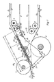
Ausführungsbeispiele der Erfindung sind in den Zeichnungen dargestellt und werden im folgenden näher beschrieben. Es zeigen:
- Fig. 1
- ein erstes erfindungsgemäßes Weichensegment zwischen oberen und unteren Förderbändern in einer ersten Schaltstellung, in schematischer Darstellung.
- Fig. 2
- Weichensegment nach Fig. 1, jedoch in einer zweiten Schaltstellung.
- Fig. 3
- ein zweites erfindungsgemäßes Weichensegment zwischen oberen und unteren Förderbändern, in schematischer Darstellung.
- Fig. 4
- eine weitere erfindungsgemäße Ausführung des Weichensegmentes.
- Fig. 1
- a first switch segment according to the invention between upper and lower conveyor belts in a first switching position, in a schematic representation.
- Fig. 2
- Turnout segment according to Fig. 1, but in a second switching position.
- Fig. 3
- a second switch segment according to the invention between upper and lower conveyor belts, in a schematic representation.
- Fig. 4
- a further embodiment of the switch segment according to the invention.
Das Transportieren von Signaturen 1 in Falzapparaten mittels sychron angetriebener, mehrerer jeweils im Abstand nebeneinander liegender oberer und unterer Förderbänder 2;3 ist allgemein bekannt geworden, z. B. durch die DE-PS 27 23 358.
Die Signaturen 1 werden entlang einem ersten Förderweg 5 zwischen den oberen und unteren Forderbändern 2 und 3 "eingeklemmt" und so transportiert. Sie dürfen auf ihrem Weg zwischen den oberen und unteren Förderbändern 2 und 3 möglichst nicht verrutschen.
Die oberen Förderbänder 2 laufen u. a. über die oberen Bänderführungsrollen 4 und 6, die in bekannter Weise an Querträgern an den Seitengestellen z. B. eines Falzapparates befestigt sind und auf unteren Förderbändern 9 eines zweiten Förderweges 11 aufliegen. Die unteren Förderbänder 3 laufen u. a. z. B. über die unteren Bänderführungsrollen 7 und 8, die bekannterweise an unteren Querträgern zwischen den Seitengestellen befestigt sind und auf unteren Förderbändern 9 eines dritten Förderweges 12 aufliegen.
Untere Förderbänder 3 und obere Förderbänder 2 verlassen unmittelbar nach den Bänderführungsrollen 4 ihren gemeinsamen Förderweg 5 und bilden zwischen sich einen spitzwinkligen Raum 13, in dem ein Weichensegment 14 einer Weiche 16 zum Umlenken von Druckprodukten z. B. Signaturen 1 Platz findet.
Den Bänderführungsrollen 6 sind Umlenkrollen 17 so zugeordnet, daß die sie berührenden Förderbänder 9 mit den oberen Förderbändern 2 jeweils einen oberen Einlaufzwickel 18 für die Signaturen 1 des zweiten Förderweges 11 bilden. Den Bänderführungsrollen 7 und 4 sind die Bänderführungsrolle 8 und eine Umlenkrolle 21 so zugeordnet, daß die Förderbänder 3 und 10 einen unteren Einlaufzwickel 22 für die Signaturen 1 des dritten Förderweges 12 bilden.
Das Weichensegment 14 weist eine obere Leitfläche 23, eine untere Leitfläche 24, eine untere Auflauffläche 26, eine linke Stirnfläche 27, eine rechte Stirnfläche 28, eine vordere und eine hintere Seitenfläche 29,31 auf.
Die oberen und unteren Leitflächen 23 und 24 sind an die Verlaufsform des Förderweges 11 ,12 der ihnen jeweils zugeordneten oberen bzw. unteren Förderbänder 2 bzw. 3 entweder total oder annähernd angepaßt. Im Ausführungsbeispiel verläuft z. B. die obere Leitfläche 23 geradlinig (plan), die untere Leitfläche 24 im ersten Abschnitt der Auflauffläche 26 geradlinig und anschließend kurvenförmig (konkav). Andere Kombinationen von Formen der Leitflächen sind natürlich möglich, z. B. konvex. Eine Schwenkachse 32 des Segments liegt außerhalb des Umrisses der Querschnitte des Weichensegments 14; d. h. im Ausführungsbeispiel nach Fig. 1 oberhalb der oberen Leitfläche 23 und im mittleren Drittel der Breite c des Weichensegments 14. Die Dicke d1 eines ersten Endes 19 des Weichensegments 14 mit der Stirnfläche 27, die unmittelbar dem Einlauf der Signaturen 1 im Weichenraum 13 gegenüberliegt, im Ausführungsbeispiel die linke Stirnfläche 27 (Weicheneingang), kann gleich oder ein Mehrfaches der Dicke d2 des zweiten Endes 20 des Weichensegments 14 und der rechten Stirnfläche 28 sein, welche den Einlaufszwickeln 18 und 22 der nachfolgenden Förderwege 11 und 12 gegenüberliegt. Über seine Länge zwischen den Seitengestellen ist das Weichensegment 14 auf ihrem ersten 19 und falls notwendig auch auf ihrem zweiten Ende 20 mit Zwischenräumen zwischen den Zinken 33 bzw. 36 (zahnartigen Vorsprüngen), kammartig gestaltet, d. h. es weist eine Mehrzahl von breiten Zinken 33;36 auf. Die Zinken 33;36 dienen zur Richtungsumlenkung der Signaturen 1 und weisen Teilflächen der oben genannten Flächen 23, 26, 27, 28 auf. Durch Zwischenräume 34,35 zwischen den Zinken 33 bzw. 36 laufen Förderbänder, z. B. das untere Förderband 3 bzw. 9,10. Durch die Anordnung der Zwischenräume 34 zwischen den Zinken 33 ist es in vorteilhafter Weise möglich, jeweils den Auflaufwinkel α; β, unter dem die Signaturen 1 auf die - je nach Weichenstellung - beteiligte Fläche z. B. 23 oder 26 auflaufen, für ein günstiges Auftreten zu gestalten. Auflauflaufwinkel ist der spitze Winkel, unter dem eine Verlängerung der oberen Leitfläche 23 eine Ebene entlang der Oberfläche des unteren Förderbandes 3 schneidet, wenn das Weichensegment 14 eine erste Weichenendstellung erreicht hat (Fig. 1); im Beispiel sind also die Förderwege 5 und 11 verbunden. Der Auflaufwinkel β ist der spitze Winkel, unter dem eine Verlängerung der Auflauffläche 26 oder diese selbst eine gedachte Ebene entlang der transportierenden Fläche des Förderbandes 3 schneidet, wenn das Weichensegment 14 eine zweite Weichenendstellung (Fig.2) erreicht hat; im Beispiel also die Förderwege 5 und 12 verbindet.Die Auflauffläche 26 kann vorteilhafterweise mit der Stirnfläche 27 einen großen Winkel bilden.
Das Weichensegment 14 erstreckt sich über die gesamte Breite der Förderstrecke der Signaturen 1 und ist mit ihren Enden mit je einem Lagerzapfen stoffschlüssig verbunden. Die Lagerzapfen sind in Seitengestellen gelagert. Ein Lagerzapfen ist z. B. mit einem Schubkurbelgetriebe verbunden, das mit einem synchron zur Hauptmaschine laufenden Antrieb formschlüssig verbunden ist.The transport of signatures 1 in folders by means of synchronously driven, several upper and lower conveyor belts 2; B. by DE-PS 27 23 358.
The signatures 1 are "clamped" along a
The upper conveyor belts 2 run, inter alia, over the upper belt guide rollers 4 and 6, which in a known manner on cross members on the side frames z. B. a folder are attached and rest on lower conveyor belts 9 of a
The belt guide rollers 6 are assigned
The
The upper and
The
Bei einer zweiten Lösung des Erfindungsgedankens (Fig. 3) sind alle Teile, mit Ausnahme des Weichensegmentes 14, gleich denen der oben beschriebenen ersten Lösung.
Im Raum 13 ist ein sich über die gesamte Breite der Signatur-Transporteinrichtung erstreckender Führungsblock 53 angeordnet. Er hat z. B. den Querschnitt eines gleichschenkligen Trapezes oder eine an dieses angenäherte Form. Die längere b Seite des Trapezes ist dabei den Umlenkrollen 17 und 21 zugewandt. Die kürzere Seite a des Trapezes liegt dem Einlauf 37 der Signaturen 1 in den Raum 13 gegenüber, die Schenkel des Trapezes begrenzen jeweils teilweise die Förderwege 11 und 12 nach innen. Die kurze Seite a des Trapezes kann auch einen konkaven Verlauf haben und / oder kammartig ausgeführt sein. Ein Weichensegment 38 hat einen flachen langgestreckten Querschnitt. Der Verlauf einer unteren Leitfläche 41 über die Breite des Weichensegments 38 ist dem Verlauf der unteren Förderbänder 3 durch den Weichenbereich auf der Strecke: Bänderführungsrolle 4 - Bänderführungsrolle 8 - Bänderführungsrolle 7, - wenn in erster Stellung der Weiche 16, der erste Förderweg 5 mit dem zweiten Förderweg 11 in Verbindung steht -, angepaßt.
Das Weichensegment 38 hat im Ausführungsbeispiel 3 und 4 einen Querschnitt, der einem Längsschnitt durch einen Keilstumpf (ungleichwinkliges Viereck) entspricht; wobei im Ausführungsbeispiel (Fig. 3) der dem Keilstumpf zugrundeliegende Keil - Querschnitt - die Form eines rechtwinkligen Dreiecks aufweist. Der dem Keilstumpf zugrundeliegende Keilquerschnitt kann aber auch die Form eines gleichschenkligen Dreieckes haben (ungleichwinkliges Viereck). Die oberen und / oder unteren Leitflächen 39,41 können aber auch andere Verläufe aufweisen, wie z.B. in Fig. 4 dargestellt. Hier ist z.B. die obere Leitfläche 39 aus zwei planen aneinanderliegenden Teilflächen 42, 43 zusammengesetzt.
Die untere Leitfläche 41 setzt sich zusammen z.B. aus einer planen Teilfläche 44, an die sich eine konkave Teilfläche 46 anschließt, die sich in einer planen Teilfläche 47 fortsetzt. Andere Verläufe der Leitflächen 39 und 41 sind natürlich möglich. Sie hängen von der Gestaltung des Verlaufes der Förderwege 5,11,12 durch die Weiche 16 ab. Ein linkes und / oder rechtes Ende 48, 49 des Weichensegments 38 kann in Zinken 50 bzw. 52 (zahnartigen Vorsprüngen) enden. Die Zinken 50, die dem Einlauf der Signaturen 1 zugewandt sind, sind so lang, daß sie zur Durchführung ihrer Funktion nicht eine Spitze aufweisen müssen. Sie können also völlig stumpf sein. Sie müssen übrigens so lang sein, daß sie sowohl in der ersten, als auch zweiten Schaltstellung der Weiche 16 mit ihrer Leitfläche 39 bzw. 41 die gedachte Ebene (Förderweg) entlang der fördernden Oberfläche der Förderbänder 2 bzw. 3 schneiden bzw. mit ihr als Grenzfall auf der gleichen horizontalen Ebene liegen.In a second solution of the inventive concept (FIG. 3), all parts, with the exception of the
A
In the
The
Im Beispiel nach Fig. 3 liegen bei zweiter Weichenstellung (Förderwege 5 und 12 haben Verbindung) untere Leitfläche 41 in einer Ebene mit der fördernden unteren Fläche des Förderbandes 2 (d.h. mit dem Förderweg) oder beide Ebenen schneiden sich in einem Winkel γ > 90o (Außenwinkel). In erster Weichenstellung (Förderwege 5 und 11 haben Verbindung) schneidet die bzw. berührt die obere Leitfläche 39 die gedachte horizontale Ebene, die entlang der Oberfläche der unteren Förderbänder 3 verläuft, wobei transportierende Oberfläche und Leitfläche 39 sich dann in einem Winkel ζ > 90o (Außenwinkel) schneiden. Die Zinken 52, die im rechten Teil 49 des Weichensegments 38 vorgesehen sind, kämmen mit zahnartigen Vorsprüngen 51 des Blockes 53. Die kürzere Seite a des Trapezes ist dabei dem rechten Ende 49 des Weichensegments 38 zugewandt. Von den beiden nichtparallelen Schenkeln bildet einer die Begrenzungsfläche 54 des Förderweges 11 auf der Oberseite des Blockes 53 nach innen, der andere eine Begrenzungsfläche 55 des Förderweges 12 auf der Unterseite des Blockes 53 nach innen. Über die Begrenzungsflächen 54 und 55 werden die Signaturen 1 bewegt. Die Begrenzungsflächen 54,55 weisen Austrittsöffnungen 56 für die Druckluft auf, die über innerhalb des Blockes 53 liegende Längsbohrungen 57 gespeist werden. Der Block 53 ist zwischen zwei Seitengestellen angeordnet und an ihren Innenseiten befestigt.In the example according to FIG. 3, with the second switch setting (conveying
Die Dicke d4 des rechten Endes 49 des Weichensegments 38 ist geringer z.B. halb so groß wie die Dicke d5 des Blockes 53 an der Fläche 55, an der er dem Weichensegment 38 zugewandt ist.
In den beiden Schaltstellungen des Weichensegmentes 38 geht die Leitfläche 39 bzw. 41 übergangslos in die Begrenzungsfläche 54 bzw. 55 über.The thickness d4 of the
In the two switch positions of the
Das Weichensegment 38 ist ebenso wie die Weichensegmente in den anderen Ausführungsbeispielen schwenkbar um eine horizontale Schwenkachse 58, um von einer ersten Weichenstellung in eine zweite zu kommen und umgekehrt. Über die Breite des Weichensegments 38,14 gesehen liegt die Schwenkachse 32, 58 im Bereich des mittleren Drittels. Die Schwenkachse 32, 58 kann auch innerhalb des Weichensegments 38, 14, oberhalb, aber auch unterhalb im Bereich des mittleren Breiten-Drittels liegen.
Der Antrieb des Weichensegments 38 erfolgt in gleicher Weise, wie beim Weichensegment 14.Like the switch segments in the other exemplary embodiments, the
The
Die Weichensegmente 14, 38 können obere und untere Leitflächen ebenso wie der Block 53 mit Austrittsöffnungen 56 für Druckluft aufweisen, die über Längsbohrungen 57 innerhalb der Weichensegmente und Rohre an eine Druckluftquelle angeschlossen sein können, um die Reibung zwischen Leitflächen und Signaturen zu vermindern.The
- 11
- Signatursignature
- 22nd
- Förderbänder, obereConveyor belts, upper
- 33rd
- Förderbänder, untereConveyor belts, lower
- 44th
- Bänderführungsrollen (2)Belt guide rollers (2)
- 55
- Förderweg, ersterFunding route, first
- 66
- Bänderführungsrollen (2, 9)Belt guide rollers (2, 9)
- 77
- Bänderführungsrollen (3, 10)Belt guide rollers (3, 10)
- 88th
- Bänderführungsrollen (3)Belt guide rollers (3)
- 99
- Förderbänder, untereConveyor belts, lower
- 1010th
- Förderbänder, obereConveyor belts, upper
- 1111
- Förderweg, zweiterFunding route, second
- 1212
- Förderweg, dritterFunding route, third
- 1313
- Raumroom
- 1414
- WeichensegmentTurnout segment
- 1515
- --
- 1616
- WeicheSwitch
- 1717th
- Umlenkrolle (9)Deflection roller (9)
- 1818th
- Einlaufzwickel, obererInlet gusset, upper
- 1919th
- Ende, erstes (14)End, first (14)
- 2020th
- Ende, zweites (14)End, second (14)
- 2121
- Umlenkrolle (10)Deflection roller (10)
- 2222
- Einlaufzwickel, untererInlet gusset, lower
- 2323
- Leitfläche, obereGuide surface, upper
- 2424th
- Leitfläche, untereGuide surface, lower
- 2525th
- --
- 2626
- Auflauffläche, untereRamp surface, lower
- 2727th
- Stirnfläche, linkeEnd face, left
- 2828
- Stirnfläche, rechteFace, right
- 2929
- Seitenfläche, vordereSide face, front
- 3030th
- --
- 3131
- Seitenfläche, hintereSide face, rear
- 3232
- SchwenkachseSwivel axis
- 3333
- ZinkenTines
- 3434
- ZwischenraumSpace
- 3535
- ZwischenraumSpace
- 3636
- ZinkenTines
- 3737
- Einlaufenema
- 3838
- WeichensegmentTurnout segment
- 3939
- Leitfläche,obereGuide surface, upper
- 4040
- --
- 4141
- Leitfläche, untereGuide surface, lower
- 4242
- Teilfläche (39)Partial area (39)
- 4343
- Teilfläche (39)Partial area (39)
- 4444
- Teilfläche (41)Partial area (41)
- 4545
- --
- 4646
- Teilfläche (41)Partial area (41)
- 4747
- Teilfläche (41)Partial area (41)
- 4848
- Ende, linkes (38)Left end (38)
- 4949
- Ende, rechtes (39)Right end (39)
- 5050
- ZinkenTines
- 5151
- Vorsprunghead Start
- 5252
- ZinkenTines
- 5353
- FührungsblockGuide block
- 5454
- BegrenzungsflächeBoundary surface
- 5555
- BegrenzungsflächeBoundary surface
- 5656
- AustrittsöffnungOutlet opening
- 5757
- LängsbohrungLongitudinal bore
- 5858
- SchwenkachseSwivel axis
- αα
- Winkelangle
- ββ
- Winkelangle
- γγ
- Winkelangle
- ζζ
- Winkelangle
- a =a =
- Seite, kürzereSide, shorter
- b =b =
- Seite, längereSide, longer
- c =c =
- Breite (14; 38)Width (14; 38)
- d1 =d1 =
- Dicke (19; 14)Thickness (19; 14)
- d2 =d2 =
- Dicke (20; 14)Thickness (20; 14)
- d4 =d4 =
- Dicke (49; 38)Thickness (49; 38)
- d5 =d5 =
- Dicke (53)Thick (53)
Claims (9)
Applications Claiming Priority (2)
| Application Number | Priority Date | Filing Date | Title |
|---|---|---|---|
| DE4005873A DE4005873A1 (en) | 1990-02-24 | 1990-02-24 | Switching points for roller rotary printing machine - has chamber-like switch segment with ends of different thickness |
| DE4005873 | 1990-02-24 |
Publications (3)
| Publication Number | Publication Date |
|---|---|
| EP0444507A2 true EP0444507A2 (en) | 1991-09-04 |
| EP0444507A3 EP0444507A3 (en) | 1992-02-26 |
| EP0444507B1 EP0444507B1 (en) | 1995-01-11 |
Family
ID=6400897
Family Applications (1)
| Application Number | Title | Priority Date | Filing Date |
|---|---|---|---|
| EP91102400A Expired - Lifetime EP0444507B1 (en) | 1990-02-24 | 1991-02-20 | Diverter in a rotary printing press |
Country Status (4)
| Country | Link |
|---|---|
| US (1) | US5108086A (en) |
| EP (1) | EP0444507B1 (en) |
| JP (1) | JPH04213547A (en) |
| DE (2) | DE4005873A1 (en) |
Cited By (1)
| Publication number | Priority date | Publication date | Assignee | Title |
|---|---|---|---|---|
| WO1998006651A1 (en) * | 1996-08-09 | 1998-02-19 | Giesecke & Devrient Gmbh | Device for changing the moving direction of a flat rectangular sheetlike product |
Families Citing this family (3)
| Publication number | Priority date | Publication date | Assignee | Title |
|---|---|---|---|---|
| DE19831062A1 (en) * | 1998-07-10 | 2000-01-13 | Gaemmerler Ag | Conveyor system |
| US6176485B1 (en) | 1999-04-05 | 2001-01-23 | Heidelberger Druckmaschinen Ag | Apparatus for diverting a continuous stream of flat products to alternate paths |
| JP2014084213A (en) * | 2012-10-25 | 2014-05-12 | Toshiba Corp | Branching and conveying apparatus for paper sheet |
Family Cites Families (21)
| Publication number | Priority date | Publication date | Assignee | Title |
|---|---|---|---|---|
| DE678472C (en) * | 1934-06-14 | 1939-07-15 | August Koenig Dr Ing | Cross cutting and collecting device |
| DE1137397B (en) * | 1960-06-15 | 1962-09-27 | Telefunken Patent | Method for controlling a flap switch in upright conveyor systems and flap switch for its execution |
| DE1169277B (en) * | 1962-05-08 | 1964-04-30 | Jagenberg Werke Ag | Method and device for separating sheets in cross-cutting or other sheet-producing machines |
| US3206191A (en) * | 1963-04-12 | 1965-09-14 | Hantscho Co George | Separating and folding apparatus for printing presses |
| DE1225565B (en) * | 1964-04-22 | 1966-09-22 | Telefunken Patent | Electromagnetic switch arrangement for conveyors of flat objects such as letters or receipts |
| JPS4910616U (en) * | 1972-04-27 | 1974-01-29 | ||
| JPS5216875B2 (en) * | 1973-08-01 | 1977-05-12 | ||
| DE2723358C2 (en) * | 1977-05-24 | 1983-11-10 | Koenig & Bauer AG, 8700 Würzburg | Folder for book folds on web-fed rotary printing machines |
| JPS5822059Y2 (en) * | 1978-08-09 | 1983-05-11 | 本田技研工業株式会社 | Evaporator |
| JPS5591630A (en) * | 1978-12-29 | 1980-07-11 | Nippon Carbon Co Ltd | Manufacture of tubular object |
| JPS6117966Y2 (en) * | 1980-12-05 | 1986-05-31 | ||
| US4373713A (en) * | 1980-12-24 | 1983-02-15 | Motter Printing Press Co. | Diverter mechanism |
| JPS57203648A (en) * | 1981-06-09 | 1982-12-14 | Canon Inc | Sheet branch device |
| US4518161A (en) * | 1982-01-22 | 1985-05-21 | Tokyo Shibaura Denki Kabushiki Kaisha | Sheet sorting apparatus |
| JPS5922849A (en) * | 1982-07-23 | 1984-02-06 | Fuji Xerox Co Ltd | Feeding apparatus for copying paper |
| GB8321519D0 (en) * | 1983-08-10 | 1983-09-14 | De La Rue Syst | Sheet feeding apparatus |
| US4722444A (en) * | 1985-04-08 | 1988-02-02 | Banctec Inc. | Method and apparatus for document processors |
| JPH072555B2 (en) * | 1986-06-25 | 1995-01-18 | 株式会社日立製作所 | Paper switching gate |
| US4729282A (en) * | 1986-07-22 | 1988-03-08 | Quad/Tech, Inc. | Sheet diverter for signature collation and method thereof |
| JPS63315442A (en) * | 1987-06-15 | 1988-12-23 | Omron Tateisi Electronics Co | Device for storing paper sheet or the like |
| JPS6428157A (en) * | 1987-07-24 | 1989-01-30 | Minolta Camera Kk | Switch-back transporting device |
-
1990
- 1990-02-24 DE DE4005873A patent/DE4005873A1/en active Granted
-
1991
- 1991-02-15 US US07/695,714 patent/US5108086A/en not_active Expired - Fee Related
- 1991-02-20 DE DE59104186T patent/DE59104186D1/en not_active Expired - Fee Related
- 1991-02-20 EP EP91102400A patent/EP0444507B1/en not_active Expired - Lifetime
- 1991-02-22 JP JP3028701A patent/JPH04213547A/en active Pending
Cited By (2)
| Publication number | Priority date | Publication date | Assignee | Title |
|---|---|---|---|---|
| WO1998006651A1 (en) * | 1996-08-09 | 1998-02-19 | Giesecke & Devrient Gmbh | Device for changing the moving direction of a flat rectangular sheetlike product |
| US6098978A (en) * | 1996-08-09 | 2000-08-08 | Giesecke & Devrient Gmbh | Device for changing the moving direction of a flat rectangular sheetlike product |
Also Published As
| Publication number | Publication date |
|---|---|
| EP0444507B1 (en) | 1995-01-11 |
| US5108086A (en) | 1992-04-28 |
| EP0444507A3 (en) | 1992-02-26 |
| JPH04213547A (en) | 1992-08-04 |
| DE59104186D1 (en) | 1995-02-23 |
| DE4005873A1 (en) | 1991-08-29 |
| DE4005873C2 (en) | 1992-06-17 |
Similar Documents
| Publication | Publication Date | Title |
|---|---|---|
| DE19503110B4 (en) | Sheet guiding device for printing machines | |
| EP0129013B1 (en) | Folding apparatus comprising a delay section | |
| DE3637110C1 (en) | Device for cutting and dividing a continuous flow of printed products | |
| DE19606821A1 (en) | Sword folding unit | |
| EP0673764A1 (en) | Device for threading webs to be printed | |
| DE10116346A1 (en) | folding | |
| DE2627810C3 (en) | Device for separating, transporting and filing compensation sheets in the course of the production of tempered chipboard, fiberboard or the like | |
| DE4005873C2 (en) | ||
| DE19940535A1 (en) | Device for redirecting signatures | |
| DE2539799B2 (en) | Blueprint machine with a repeating device | |
| DE10337248B4 (en) | Web spreading method and web spreading device | |
| EP0944545B1 (en) | Device for distributing a flow of signatures | |
| EP0091582B1 (en) | Device for drawing asunder piles of folded products mutually staggered transversely to the direction of transport | |
| DE19924996A1 (en) | Chain conveyor for sheet-processing printing machine | |
| DE102005045041B3 (en) | Device for drawing a material strip and/or a strand with several material strips into a folding device comprises a guiding rail guided along a folding funnel having a shape-variable guiding rail section on the funnel | |
| DE10304617B4 (en) | Sheet feeder for a sheet processing machine | |
| DE9017606U1 (en) | Switch in a web-fed rotary printing press | |
| EP1110894B1 (en) | Method and device for folding sheets of material | |
| EP1237805B1 (en) | Device for deviating an overlapping stream on a roller table | |
| DE19516655C2 (en) | Device for bringing together two material webs conveyed in a web-fed rotary printing press | |
| DE3332809A1 (en) | Belt retarding section for a folding apparatus | |
| DE10048295B4 (en) | Folding structure with a copy weir and method for dividing a product stream into two partial streams | |
| DE19754151A9 (en) | Folding apparatus for printers | |
| DE2523424C2 (en) | Conveyor device on a zigzag folder for zigzag folding webs | |
| DE19649294C2 (en) | Folder for the production of book sections |
Legal Events
| Date | Code | Title | Description |
|---|---|---|---|
| PUAI | Public reference made under article 153(3) epc to a published international application that has entered the european phase |
Free format text: ORIGINAL CODE: 0009012 |
|
| AK | Designated contracting states |
Kind code of ref document: A2 Designated state(s): CH DE FR GB IT LI SE |
|
| PUAL | Search report despatched |
Free format text: ORIGINAL CODE: 0009013 |
|
| AK | Designated contracting states |
Kind code of ref document: A3 Designated state(s): CH DE FR GB IT LI SE |
|
| 17P | Request for examination filed |
Effective date: 19920331 |
|
| 17Q | First examination report despatched |
Effective date: 19930810 |
|
| ITF | It: translation for a ep patent filed | ||
| GRAA | (expected) grant |
Free format text: ORIGINAL CODE: 0009210 |
|
| AK | Designated contracting states |
Kind code of ref document: B1 Designated state(s): CH DE FR GB IT LI SE |
|
| EAL | Se: european patent in force in sweden |
Ref document number: 91102400.8 |
|
| GBT | Gb: translation of ep patent filed (gb section 77(6)(a)/1977) |
Effective date: 19950119 |
|
| REF | Corresponds to: |
Ref document number: 59104186 Country of ref document: DE Date of ref document: 19950223 |
|
| ET | Fr: translation filed | ||
| PGFP | Annual fee paid to national office [announced via postgrant information from national office to epo] |
Ref country code: DE Payment date: 19950502 Year of fee payment: 5 |
|
| PLBE | No opposition filed within time limit |
Free format text: ORIGINAL CODE: 0009261 |
|
| STAA | Information on the status of an ep patent application or granted ep patent |
Free format text: STATUS: NO OPPOSITION FILED WITHIN TIME LIMIT |
|
| 26N | No opposition filed | ||
| PG25 | Lapsed in a contracting state [announced via postgrant information from national office to epo] |
Ref country code: DE Effective date: 19961101 |
|
| PGFP | Annual fee paid to national office [announced via postgrant information from national office to epo] |
Ref country code: GB Payment date: 20010125 Year of fee payment: 11 |
|
| PGFP | Annual fee paid to national office [announced via postgrant information from national office to epo] |
Ref country code: SE Payment date: 20010221 Year of fee payment: 11 |
|
| PGFP | Annual fee paid to national office [announced via postgrant information from national office to epo] |
Ref country code: FR Payment date: 20010222 Year of fee payment: 11 |
|
| PGFP | Annual fee paid to national office [announced via postgrant information from national office to epo] |
Ref country code: CH Payment date: 20010302 Year of fee payment: 11 |
|
| REG | Reference to a national code |
Ref country code: GB Ref legal event code: IF02 |
|
| PG25 | Lapsed in a contracting state [announced via postgrant information from national office to epo] |
Ref country code: GB Free format text: LAPSE BECAUSE OF NON-PAYMENT OF DUE FEES Effective date: 20020220 |
|
| PG25 | Lapsed in a contracting state [announced via postgrant information from national office to epo] |
Ref country code: SE Free format text: LAPSE BECAUSE OF NON-PAYMENT OF DUE FEES Effective date: 20020221 |
|
| PG25 | Lapsed in a contracting state [announced via postgrant information from national office to epo] |
Ref country code: LI Free format text: LAPSE BECAUSE OF NON-PAYMENT OF DUE FEES Effective date: 20020228 Ref country code: CH Free format text: LAPSE BECAUSE OF NON-PAYMENT OF DUE FEES Effective date: 20020228 |
|
| EUG | Se: european patent has lapsed |
Ref document number: 91102400.8 |
|
| GBPC | Gb: european patent ceased through non-payment of renewal fee |
Effective date: 20020220 |
|
| REG | Reference to a national code |
Ref country code: CH Ref legal event code: PL |
|
| PG25 | Lapsed in a contracting state [announced via postgrant information from national office to epo] |
Ref country code: FR Free format text: LAPSE BECAUSE OF NON-PAYMENT OF DUE FEES Effective date: 20021031 |
|
| REG | Reference to a national code |
Ref country code: FR Ref legal event code: ST |
|
| PG25 | Lapsed in a contracting state [announced via postgrant information from national office to epo] |
Ref country code: IT Free format text: LAPSE BECAUSE OF NON-PAYMENT OF DUE FEES;WARNING: LAPSES OF ITALIAN PATENTS WITH EFFECTIVE DATE BEFORE 2007 MAY HAVE OCCURRED AT ANY TIME BEFORE 2007. THE CORRECT EFFECTIVE DATE MAY BE DIFFERENT FROM THE ONE RECORDED. Effective date: 20050220 |