EP0444507A2 - Déviateur dans une machine à imprimer rotative - Google Patents
Déviateur dans une machine à imprimer rotative Download PDFInfo
- Publication number
- EP0444507A2 EP0444507A2 EP91102400A EP91102400A EP0444507A2 EP 0444507 A2 EP0444507 A2 EP 0444507A2 EP 91102400 A EP91102400 A EP 91102400A EP 91102400 A EP91102400 A EP 91102400A EP 0444507 A2 EP0444507 A2 EP 0444507A2
- Authority
- EP
- European Patent Office
- Prior art keywords
- switch
- segment
- signatures
- block
- switch segment
- Prior art date
- Legal status (The legal status is an assumption and is not a legal conclusion. Google has not performed a legal analysis and makes no representation as to the accuracy of the status listed.)
- Granted
Links
- 230000001154 acute effect Effects 0.000 claims description 3
- 238000010276 construction Methods 0.000 description 2
- 241000792859 Enema Species 0.000 description 1
- 239000000654 additive Substances 0.000 description 1
- 239000007920 enema Substances 0.000 description 1
- 229940095399 enema Drugs 0.000 description 1
- 239000000463 material Substances 0.000 description 1
Images


Classifications
-
- B—PERFORMING OPERATIONS; TRANSPORTING
- B65—CONVEYING; PACKING; STORING; HANDLING THIN OR FILAMENTARY MATERIAL
- B65H—HANDLING THIN OR FILAMENTARY MATERIAL, e.g. SHEETS, WEBS, CABLES
- B65H29/00—Delivering or advancing articles from machines; Advancing articles to or into piles
- B65H29/58—Article switches or diverters
-
- B—PERFORMING OPERATIONS; TRANSPORTING
- B65—CONVEYING; PACKING; STORING; HANDLING THIN OR FILAMENTARY MATERIAL
- B65H—HANDLING THIN OR FILAMENTARY MATERIAL, e.g. SHEETS, WEBS, CABLES
- B65H2404/00—Parts for transporting or guiding the handled material
- B65H2404/20—Belts
- B65H2404/26—Particular arrangement of belt, or belts
- B65H2404/261—Arrangement of belts, or belt(s) / roller(s) facing each other for forming a transport nip
-
- B—PERFORMING OPERATIONS; TRANSPORTING
- B65—CONVEYING; PACKING; STORING; HANDLING THIN OR FILAMENTARY MATERIAL
- B65H—HANDLING THIN OR FILAMENTARY MATERIAL, e.g. SHEETS, WEBS, CABLES
- B65H2701/00—Handled material; Storage means
- B65H2701/10—Handled articles or webs
- B65H2701/19—Specific article or web
- B65H2701/1932—Signatures, folded printed matter, newspapers or parts thereof and books
Definitions
- the invention relates to a controllable switch in a paper transport device of a web-fed rotary printing press.
- Controllable characters in a paper transport direction of a web-fed rotary printing press have become known from DE-PS 6 78 472.
- DE-OS 22 33 750 shows a switch controllable in time in the output of a folder of a web-fed rotary printing press.
- This publication also shows a typical tape transport system that shows how printed, folded signatures are transported between tapes from one place to a second.
- the switch segments used up to now are characterized in that the signatures to be diverted run up against a flat, relatively thin tip of the switch segment and quickly weaken this tip by material removal.
- the invention has for its object to provide a switch segment as part of a switch in a signature transport device of a web-fed rotary printing press, in particular, a folder with which a long service life with respect to wear can be achieved even at high production speeds.
- the advantages which can be achieved with the invention consist in particular in that, in addition to avoiding the above-mentioned disadvantages of the prior art, the point of impact of the signatures does not lie on the legs of the thin, flat-drawn tip of the switch segment.
- the point of application of force for controlling the switch segment does not have to be in the end opposite the tip of the switch segment, so a smaller drive torque is necessary.
- the turnout segment can be of shorter construction compared to flat-drawn turnout segments, so that the distance over which signatures without double tape guidance be promoted, becomes shorter.
- the signature inlet between the conveyor belt and the switch segment can initially be designed in a funnel shape.
- the switch segments since they are made thicker, can be made comb-like at one or both ends, so that the conveyor belt and / or guide rollers can run in the space between two prongs of the switch segment. This ensures that the upper and lower conveyor belts can run closer together in the switch segment area. This also enables a more compact construction of the entire turnout and thus short deflection paths without double conveyor belt guidance.
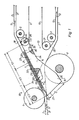
- the transport of signatures 1 in folders by means of synchronously driven, several upper and lower conveyor belts 2; B. by DE-PS 27 23 358.
- the signatures 1 are "clamped” along a first conveyor path 5 between the upper and lower conveyor belts 2 and 3 and are thus transported. As far as possible, they must not slip on their way between the upper and lower conveyor belts 2 and 3.
- the upper conveyor belts 2 run, inter alia, over the upper belt guide rollers 4 and 6, which in a known manner on cross members on the side frames z.
- B. a folder are attached and rest on lower conveyor belts 9 of a second conveyor 11.
- the lower conveyor belts 3 run, for example, over the lower belt guide rollers 7 and 8, which are known to be attached to lower cross members between the side frames and rest on lower conveyor belts 9 of a third conveyor path 12.
- Lower conveyor belts 3 and upper conveyor belts 2 leave their common conveyor path 5 immediately after the belt guide rollers 4 and form between them an acute-angled space 13 in which a switch segment 14 of a switch 16 for deflecting printed products, for. B. Signatures 1 place.
- the belt guide rollers 6 are assigned deflection rollers 17 so that the conveyor belts 9 touching them form an upper inlet gusset 18 for the signatures 1 of the second conveyor path 11 with the upper conveyor belts 2.
- the tape guide rollers 7 and 4, the belt guide roller 8 and a deflection roller 21 are assigned so that the conveyor belts 3 and 10 form a lower inlet gusset 22 for the signatures 1 of the third conveyor path 12.
- the switch segment 14 has an upper guide surface 23, a lower guide surface 24, a lower ramp surface 26, a left end surface 27, a right end surface 28, a front and a rear side surface 29, 31.
- the upper and lower guide surfaces 23 and 24 are either totally or approximately adapted to the shape of the conveying path 11, 12 of the upper and lower conveyor belts 2 and 3 respectively assigned to them.
- z. B the upper guide surface 23 straight (plan), the lower guide surface 24 in the first section of the run-up surface 26 straight and then curved (concave).
- a pivot axis 32 of the segment lies outside the outline of the cross sections of the switch segment 14; 1 above the upper guide surface 23 and in the middle third of the width c of the switch segment 14.
- the thickness d1 of a first end 19 of the switch segment 14 with the end face 27, which is directly opposite the entry of the signatures 1 in the switch space 13, in the exemplary embodiment, the left end face 27 (turnout input) can be equal to or a multiple of the thickness d2 of the second end 20 of the turnout segment 14 and the right end face 28, which lies opposite the inlet gussets 18 and 22 of the subsequent conveying paths 11 and 12.
- the switch segment 14 is on its first 19 and if necessary also on its second end 20 with spaces between the prongs 33 or 36 (tooth-like projections), designed like a comb, ie it has a plurality of wide tines 33; 36.
- the tines 33; 36 serve to deflect the direction of the signatures 1 and have partial surfaces of the above-mentioned surfaces 23, 26, 27, 28.
- Conveyor belts e.g. B. the lower conveyor belt 3 or 9.10.
- the arrangement of the intermediate spaces 34 between the tines 33 makes it possible in an advantageous manner to in each case the run-up angle ⁇ ; ⁇ , under which the signatures 1 on the - depending on the course - involved area z. B.
- Run-up angle is the acute angle at which an extension of the upper guide surface 23 intersects a plane along the surface of the lower conveyor belt 3 when the switch segment 14 has reached a first switch end position (FIG. 1); in the example, the funding routes 5 and 11 are connected.
- the run-up angle ⁇ is the acute angle at which an extension of the run-up surface 26 or this intersects an imaginary plane along the transporting surface of the conveyor belt 3 when the turnout segment 14 has reached a second turnout end position (FIG. 2); in the example thus connects the conveying paths 5 and 12.
- the run-up surface 26 can advantageously form a large angle with the end surface 27.
- the switch segment 14 extends over the entire width of the conveying path of the signatures 1 and is connected with its ends to a bearing journal in a cohesive manner.
- the trunnions are stored in side frames.
- a journal is e.g. B. connected to a sliding crank gear, which is positively connected to a drive running synchronously with the main machine.
- FIG. 3 In a second solution of the inventive concept (FIG. 3), all parts, with the exception of the switch segment 14, are the same as those of the first solution described above.
- a guide block 53 which extends over the entire width of the signature transport device is arranged in space 13. He has z.
- B the cross section of an isosceles trapezoid or a shape approximated to this. The longer b side of the trapezoid faces the deflection rollers 17 and 21. The shorter side a of the trapezoid lies opposite the inlet 37 of the signatures 1 into the space 13, the legs of the trapezoid partially limit the conveying paths 11 and 12 to the inside.
- the short side a of the trapezoid can also have a concave course and / or be comb-like.
- a switch segment 38 has a flat, elongated cross section. The course of a lower guide surface 41 across the width of the switch segment 38 is the course of the lower conveyor belts 3 through the switch area on the route: belt guide roller 4 - belt guide roller 8 - belt guide roller 7, - when the switch 16 is in the first position, the first conveyor path 5 with the second conveyor path 11 is connected -, adapted.
- the switch segment 38 has a cross section which corresponds to a longitudinal section through a wedge stump (non-angular square); wherein in the exemplary embodiment (FIG.
- the wedge on which the wedge stump is based - cross section - has the shape of a right-angled triangle.
- the wedge cross-section on which the wedge stump is based can also have the shape of an isosceles triangle (non-angled square).
- the upper and / or lower guide surfaces 39, 41 can, however, also have other courses, such as in FIG. 4 shown.
- the upper guide surface 39 is composed of two flat partial surfaces 42, 43 lying one against the other.
- the lower guide surface 41 is composed, for example, of a flat partial surface 44 which is adjoined by a concave partial surface 46 which continues in a flat partial surface 47.
- Other courses of the guide surfaces 39 and 41 are of course possible.
- a left and / or right end 48, 49 of the switch segment 38 can end in prongs 50 and 52 (tooth-like projections).
- the tines 50 which face the inlet of the signatures 1, are so long that they do not have to have a tip to perform their function. So you can be completely blunt. Incidentally, they must be so long that they cut the imaginary plane (conveying path) along the conveying surface of the conveyor belts 2 and 3, respectively, with the guide surface 39 and 41 in the first and second switching positions of the switch 16 and with it as Limit case are on the same horizontal plane.
- the lower guide surface 41 lies in one plane with the conveying lower surface of the conveyor belt 2 (ie with the conveying path) or both planes intersect at an angle ⁇ > 90 ° (Outside angle).
- the upper guide surface 39 intersects or touches the imaginary horizontal plane which runs along the surface of the lower conveyor belts 3, the transporting surface and guide surface 39 then being at an angle ⁇ > 90 ° Cut (outside angle).
- the tines 52 which are provided in the right part 49 of the turnout segment 38, mesh with tooth-like projections 51 of the block 53.
- the shorter side a of the trapezoid faces the right end 49 of the turnout segment 38.
- one forms the boundary surface 54 of the conveying path 11 on the top of the block 53 inwards
- the other a boundary surface 55 of the conveying path 12 on the underside of the block 53 inwards.
- the signatures 1 are moved over the boundary surfaces 54 and 55.
- the boundary surfaces 54, 55 have outlet openings 56 for the compressed air, which are fed via longitudinal bores 57 located within the block 53.
- the block 53 is arranged between two side frames and fastened on their inner sides.
- the thickness d4 of the right end 49 of the turnout segment 38 is less, for example, half as large as the thickness d5 of the block 53 on the surface 55 on which it faces the turnout segment 38.
- the guide surface 39 or 41 merges seamlessly into the boundary surface 54 or 55.
- the switch segment 38 can be pivoted about a horizontal pivot axis 58 in order to move from a first switch position to a second and vice versa. Seen over the width of the switch segment 38, 14, the pivot axis 32, 58 lies in the region of the middle third. The Pivot axis 32, 58 can also lie within the switch segment 38, 14, above, but also below in the region of the middle third of the width.
- the turnout segment 38 is driven in the same way as for the turnout segment 14.
- the switch segments 14, 38 can have upper and lower guide surfaces as well as the block 53 with outlet openings 56 for compressed air, which can be connected to a compressed air source via longitudinal bores 57 within the switch segments and pipes in order to reduce the friction between guide surfaces and signatures.
Landscapes
- Engineering & Computer Science (AREA)
- Mechanical Engineering (AREA)
- Separation, Sorting, Adjustment, Or Bending Of Sheets To Be Conveyed (AREA)
- Folding Of Thin Sheet-Like Materials, Special Discharging Devices, And Others (AREA)
Applications Claiming Priority (2)
| Application Number | Priority Date | Filing Date | Title |
|---|---|---|---|
| DE4005873A DE4005873A1 (de) | 1990-02-24 | 1990-02-24 | Weiche in einer rollenrotationsdruckmaschine |
| DE4005873 | 1990-02-24 |
Publications (3)
| Publication Number | Publication Date |
|---|---|
| EP0444507A2 true EP0444507A2 (fr) | 1991-09-04 |
| EP0444507A3 EP0444507A3 (en) | 1992-02-26 |
| EP0444507B1 EP0444507B1 (fr) | 1995-01-11 |
Family
ID=6400897
Family Applications (1)
| Application Number | Title | Priority Date | Filing Date |
|---|---|---|---|
| EP91102400A Expired - Lifetime EP0444507B1 (fr) | 1990-02-24 | 1991-02-20 | Déviateur dans une machine à imprimer rotative |
Country Status (4)
| Country | Link |
|---|---|
| US (1) | US5108086A (fr) |
| EP (1) | EP0444507B1 (fr) |
| JP (1) | JPH04213547A (fr) |
| DE (2) | DE4005873A1 (fr) |
Cited By (1)
| Publication number | Priority date | Publication date | Assignee | Title |
|---|---|---|---|---|
| WO1998006651A1 (fr) * | 1996-08-09 | 1998-02-19 | Giesecke & Devrient Gmbh | Dispositif pour modifier le sens de mouvement d'un produit se presentant sous forme de feuille rectangulaire plate |
Families Citing this family (3)
| Publication number | Priority date | Publication date | Assignee | Title |
|---|---|---|---|---|
| DE19831062A1 (de) * | 1998-07-10 | 2000-01-13 | Gaemmerler Ag | Fördersystem |
| US6176485B1 (en) | 1999-04-05 | 2001-01-23 | Heidelberger Druckmaschinen Ag | Apparatus for diverting a continuous stream of flat products to alternate paths |
| JP2014084213A (ja) * | 2012-10-25 | 2014-05-12 | Toshiba Corp | 紙葉類分岐搬送装置 |
Family Cites Families (21)
| Publication number | Priority date | Publication date | Assignee | Title |
|---|---|---|---|---|
| DE678472C (de) * | 1934-06-14 | 1939-07-15 | August Koenig Dr Ing | Querschneid- und Sammelvorrichtung |
| DE1137397B (de) * | 1960-06-15 | 1962-09-27 | Telefunken Patent | Verfahren zum Steuern einer Klappenweiche in Hochkantfoerder-anlagen und Klappenweiche zu dessen Ausfuehrung |
| DE1169277B (de) * | 1962-05-08 | 1964-04-30 | Jagenberg Werke Ag | Verfahren und Vorrichtung zum Ausscheiden von Bogen in Querschneide- oder sonstigen bogenerzeugenden Maschinen |
| US3206191A (en) * | 1963-04-12 | 1965-09-14 | Hantscho Co George | Separating and folding apparatus for printing presses |
| DE1225565B (de) * | 1964-04-22 | 1966-09-22 | Telefunken Patent | Elektromagnetische Weichenanordnung bei Foerderern von flachen Gegenstaenden wie insbesondere Briefen oder Belegen |
| JPS4910616U (fr) * | 1972-04-27 | 1974-01-29 | ||
| JPS5216875B2 (fr) * | 1973-08-01 | 1977-05-12 | ||
| DE2723358C2 (de) * | 1977-05-24 | 1983-11-10 | Koenig & Bauer AG, 8700 Würzburg | Falzapparat für Buchfalzungen an Rollenrotationsdruckmaschinen |
| JPS5822059Y2 (ja) * | 1978-08-09 | 1983-05-11 | 本田技研工業株式会社 | 蒸発器 |
| JPS5591630A (en) * | 1978-12-29 | 1980-07-11 | Nippon Carbon Co Ltd | Manufacture of tubular object |
| JPS6117966Y2 (fr) * | 1980-12-05 | 1986-05-31 | ||
| US4373713A (en) * | 1980-12-24 | 1983-02-15 | Motter Printing Press Co. | Diverter mechanism |
| JPS57203648A (en) * | 1981-06-09 | 1982-12-14 | Canon Inc | Sheet branch device |
| US4518161A (en) * | 1982-01-22 | 1985-05-21 | Tokyo Shibaura Denki Kabushiki Kaisha | Sheet sorting apparatus |
| JPS5922849A (ja) * | 1982-07-23 | 1984-02-06 | Fuji Xerox Co Ltd | 複写用紙給紙装置 |
| GB8321519D0 (en) * | 1983-08-10 | 1983-09-14 | De La Rue Syst | Sheet feeding apparatus |
| US4722444A (en) * | 1985-04-08 | 1988-02-02 | Banctec Inc. | Method and apparatus for document processors |
| JPH072555B2 (ja) * | 1986-06-25 | 1995-01-18 | 株式会社日立製作所 | 紙葉切換えゲ−ト |
| US4729282A (en) * | 1986-07-22 | 1988-03-08 | Quad/Tech, Inc. | Sheet diverter for signature collation and method thereof |
| JPS63315442A (ja) * | 1987-06-15 | 1988-12-23 | Omron Tateisi Electronics Co | 紙葉類のストア装置 |
| JPS6428157A (en) * | 1987-07-24 | 1989-01-30 | Minolta Camera Kk | Switch-back transporting device |
-
1990
- 1990-02-24 DE DE4005873A patent/DE4005873A1/de active Granted
-
1991
- 1991-02-15 US US07/695,714 patent/US5108086A/en not_active Expired - Fee Related
- 1991-02-20 DE DE59104186T patent/DE59104186D1/de not_active Expired - Fee Related
- 1991-02-20 EP EP91102400A patent/EP0444507B1/fr not_active Expired - Lifetime
- 1991-02-22 JP JP3028701A patent/JPH04213547A/ja active Pending
Cited By (2)
| Publication number | Priority date | Publication date | Assignee | Title |
|---|---|---|---|---|
| WO1998006651A1 (fr) * | 1996-08-09 | 1998-02-19 | Giesecke & Devrient Gmbh | Dispositif pour modifier le sens de mouvement d'un produit se presentant sous forme de feuille rectangulaire plate |
| US6098978A (en) * | 1996-08-09 | 2000-08-08 | Giesecke & Devrient Gmbh | Device for changing the moving direction of a flat rectangular sheetlike product |
Also Published As
| Publication number | Publication date |
|---|---|
| EP0444507B1 (fr) | 1995-01-11 |
| US5108086A (en) | 1992-04-28 |
| EP0444507A3 (en) | 1992-02-26 |
| JPH04213547A (ja) | 1992-08-04 |
| DE59104186D1 (de) | 1995-02-23 |
| DE4005873A1 (de) | 1991-08-29 |
| DE4005873C2 (fr) | 1992-06-17 |
Similar Documents
| Publication | Publication Date | Title |
|---|---|---|
| DE19503110B4 (de) | Bogenleiteinrichtung für Druckmaschinen | |
| EP0129013B1 (fr) | Appareil de pliage avec un parcours de retard | |
| DE3637110C1 (de) | Vorrichtung zum Schneiden und Aufteilen eines kontinuierlichen Stroms von Druckprodukten | |
| DE19606821A1 (de) | Schwertfalzwerk | |
| EP0673764A1 (fr) | Dispositif pour introduire des bandes à imprimer | |
| DE10116346A1 (de) | Falzapparat | |
| DE2627810C3 (de) | Vorrichtung zum Vereinzeln, Transportieren und Ablegen von Vergütungsbögen im Zuge der Herstellung von vergüteten Spanplatten, Faserplatten o.dgl | |
| DE4005873C2 (fr) | ||
| DE19940535A1 (de) | Vorrichtung zum Umlenken von Signaturen | |
| DE2539799B2 (de) | Lichtpausmaschine mit einer Repetiervorrichtung | |
| DE10337248B4 (de) | Bahnspreizverfahren und Bahnspreizvorrichtung | |
| EP0944545B1 (fr) | Dispositif pour la repartition d'un flux de cahiers | |
| EP0091582B1 (fr) | Dispositif pour étirer des piles de produits pliés mutuellement déplacées transversalement par rapport à la direction de transport | |
| DE19924996A1 (de) | Kettenförderer für eine Bogen verarbeitende Druckmaschine | |
| DE102005045041B3 (de) | Vorrichtung und ein Verfahren zur Verwendung einer Vorrichtung zum Einziehen mindestens einer Materialbahn bzw. mindestens eines Bahnstrangs in einen Falzapparat | |
| DE10304617B4 (de) | Bogenförderer für eine Bogen verarbeitende Maschine | |
| DE9017606U1 (de) | Weiche in einer Rollenrotationsdruckmaschine | |
| EP1110894B1 (fr) | Méthode et dispositif pour plier des feuilles de matériau | |
| EP1237805B1 (fr) | Dispositif permettant de devier un courant lamellaire sur une table a rouleaux | |
| DE19516655C2 (de) | Vorrichtung zum Zusammenführen von zwei in einer Rollenrotationsdruckmaschine geförderten Materialbahnen | |
| DE3332809A1 (de) | Bandverzoegerungsstrecke fuer einen falzapparat | |
| DE10048295B4 (de) | Falzaufbau mit einer Exemplarweiche und Verfahren zum Aufteilen eines Produktstroms in zwei Teilströme | |
| DE19754151A9 (de) | Einrichtung zur Verbesserung der Falzgenauigkeit im Falzapparat | |
| DE2523424C2 (de) | Fördervorrichtung an einem Zickzackfalzapparat zum Zickzackfalzen von Bahnen | |
| DE19649294C2 (de) | Falzapparat zur Herstellung von Buchsektionen |
Legal Events
| Date | Code | Title | Description |
|---|---|---|---|
| PUAI | Public reference made under article 153(3) epc to a published international application that has entered the european phase |
Free format text: ORIGINAL CODE: 0009012 |
|
| AK | Designated contracting states |
Kind code of ref document: A2 Designated state(s): CH DE FR GB IT LI SE |
|
| PUAL | Search report despatched |
Free format text: ORIGINAL CODE: 0009013 |
|
| AK | Designated contracting states |
Kind code of ref document: A3 Designated state(s): CH DE FR GB IT LI SE |
|
| 17P | Request for examination filed |
Effective date: 19920331 |
|
| 17Q | First examination report despatched |
Effective date: 19930810 |
|
| ITF | It: translation for a ep patent filed | ||
| GRAA | (expected) grant |
Free format text: ORIGINAL CODE: 0009210 |
|
| AK | Designated contracting states |
Kind code of ref document: B1 Designated state(s): CH DE FR GB IT LI SE |
|
| EAL | Se: european patent in force in sweden |
Ref document number: 91102400.8 |
|
| GBT | Gb: translation of ep patent filed (gb section 77(6)(a)/1977) |
Effective date: 19950119 |
|
| REF | Corresponds to: |
Ref document number: 59104186 Country of ref document: DE Date of ref document: 19950223 |
|
| ET | Fr: translation filed | ||
| PGFP | Annual fee paid to national office [announced via postgrant information from national office to epo] |
Ref country code: DE Payment date: 19950502 Year of fee payment: 5 |
|
| PLBE | No opposition filed within time limit |
Free format text: ORIGINAL CODE: 0009261 |
|
| STAA | Information on the status of an ep patent application or granted ep patent |
Free format text: STATUS: NO OPPOSITION FILED WITHIN TIME LIMIT |
|
| 26N | No opposition filed | ||
| PG25 | Lapsed in a contracting state [announced via postgrant information from national office to epo] |
Ref country code: DE Effective date: 19961101 |
|
| PGFP | Annual fee paid to national office [announced via postgrant information from national office to epo] |
Ref country code: GB Payment date: 20010125 Year of fee payment: 11 |
|
| PGFP | Annual fee paid to national office [announced via postgrant information from national office to epo] |
Ref country code: SE Payment date: 20010221 Year of fee payment: 11 |
|
| PGFP | Annual fee paid to national office [announced via postgrant information from national office to epo] |
Ref country code: FR Payment date: 20010222 Year of fee payment: 11 |
|
| PGFP | Annual fee paid to national office [announced via postgrant information from national office to epo] |
Ref country code: CH Payment date: 20010302 Year of fee payment: 11 |
|
| REG | Reference to a national code |
Ref country code: GB Ref legal event code: IF02 |
|
| PG25 | Lapsed in a contracting state [announced via postgrant information from national office to epo] |
Ref country code: GB Free format text: LAPSE BECAUSE OF NON-PAYMENT OF DUE FEES Effective date: 20020220 |
|
| PG25 | Lapsed in a contracting state [announced via postgrant information from national office to epo] |
Ref country code: SE Free format text: LAPSE BECAUSE OF NON-PAYMENT OF DUE FEES Effective date: 20020221 |
|
| PG25 | Lapsed in a contracting state [announced via postgrant information from national office to epo] |
Ref country code: LI Free format text: LAPSE BECAUSE OF NON-PAYMENT OF DUE FEES Effective date: 20020228 Ref country code: CH Free format text: LAPSE BECAUSE OF NON-PAYMENT OF DUE FEES Effective date: 20020228 |
|
| EUG | Se: european patent has lapsed |
Ref document number: 91102400.8 |
|
| GBPC | Gb: european patent ceased through non-payment of renewal fee |
Effective date: 20020220 |
|
| REG | Reference to a national code |
Ref country code: CH Ref legal event code: PL |
|
| PG25 | Lapsed in a contracting state [announced via postgrant information from national office to epo] |
Ref country code: FR Free format text: LAPSE BECAUSE OF NON-PAYMENT OF DUE FEES Effective date: 20021031 |
|
| REG | Reference to a national code |
Ref country code: FR Ref legal event code: ST |
|
| PG25 | Lapsed in a contracting state [announced via postgrant information from national office to epo] |
Ref country code: IT Free format text: LAPSE BECAUSE OF NON-PAYMENT OF DUE FEES;WARNING: LAPSES OF ITALIAN PATENTS WITH EFFECTIVE DATE BEFORE 2007 MAY HAVE OCCURRED AT ANY TIME BEFORE 2007. THE CORRECT EFFECTIVE DATE MAY BE DIFFERENT FROM THE ONE RECORDED. Effective date: 20050220 |