EP0444547A1 - Méthode et dispositif pour convoyer des bandes de fermeture en vue de les transférer à des paquets - Google Patents
Méthode et dispositif pour convoyer des bandes de fermeture en vue de les transférer à des paquets Download PDFInfo
- Publication number
- EP0444547A1 EP0444547A1 EP19910102639 EP91102639A EP0444547A1 EP 0444547 A1 EP0444547 A1 EP 0444547A1 EP 19910102639 EP19910102639 EP 19910102639 EP 91102639 A EP91102639 A EP 91102639A EP 0444547 A1 EP0444547 A1 EP 0444547A1
- Authority
- EP
- European Patent Office
- Prior art keywords
- banderoles
- magazine
- material web
- banderole
- separated
- Prior art date
- Legal status (The legal status is an assumption and is not a legal conclusion. Google has not performed a legal analysis and makes no representation as to the accuracy of the status listed.)
- Granted
Links
Images




Classifications
-
- B—PERFORMING OPERATIONS; TRANSPORTING
- B65—CONVEYING; PACKING; STORING; HANDLING THIN OR FILAMENTARY MATERIAL
- B65C—LABELLING OR TAGGING MACHINES, APPARATUS, OR PROCESSES
- B65C9/00—Details of labelling machines or apparatus
- B65C9/08—Label feeding
- B65C9/18—Label feeding from strips, e.g. from rolls
- B65C9/1803—Label feeding from strips, e.g. from rolls the labels being cut from a strip
- B65C9/183—Label feeding from strips, e.g. from rolls the labels being cut from a strip and transferred by gripping means or feeding rollers
-
- B—PERFORMING OPERATIONS; TRANSPORTING
- B65—CONVEYING; PACKING; STORING; HANDLING THIN OR FILAMENTARY MATERIAL
- B65C—LABELLING OR TAGGING MACHINES, APPARATUS, OR PROCESSES
- B65C9/00—Details of labelling machines or apparatus
- B65C9/08—Label feeding
- B65C9/10—Label magazines
-
- B—PERFORMING OPERATIONS; TRANSPORTING
- B65—CONVEYING; PACKING; STORING; HANDLING THIN OR FILAMENTARY MATERIAL
- B65C—LABELLING OR TAGGING MACHINES, APPARATUS, OR PROCESSES
- B65C9/00—Details of labelling machines or apparatus
- B65C9/08—Label feeding
- B65C9/12—Removing separate labels from stacks
-
- B—PERFORMING OPERATIONS; TRANSPORTING
- B65—CONVEYING; PACKING; STORING; HANDLING THIN OR FILAMENTARY MATERIAL
- B65C—LABELLING OR TAGGING MACHINES, APPARATUS, OR PROCESSES
- B65C9/00—Details of labelling machines or apparatus
- B65C9/08—Label feeding
- B65C9/18—Label feeding from strips, e.g. from rolls
- B65C9/1803—Label feeding from strips, e.g. from rolls the labels being cut from a strip
- B65C9/1815—Label feeding from strips, e.g. from rolls the labels being cut from a strip and transferred by suction means
- B65C9/1819—Label feeding from strips, e.g. from rolls the labels being cut from a strip and transferred by suction means the suction means being a vacuum drum
-
- B—PERFORMING OPERATIONS; TRANSPORTING
- B65—CONVEYING; PACKING; STORING; HANDLING THIN OR FILAMENTARY MATERIAL
- B65H—HANDLING THIN OR FILAMENTARY MATERIAL, e.g. SHEETS, WEBS, CABLES
- B65H1/00—Supports or magazines for piles from which articles are to be separated
- B65H1/30—Supports or magazines for piles from which articles are to be separated with means for replenishing the pile during continuous separation of articles therefrom
-
- Y—GENERAL TAGGING OF NEW TECHNOLOGICAL DEVELOPMENTS; GENERAL TAGGING OF CROSS-SECTIONAL TECHNOLOGIES SPANNING OVER SEVERAL SECTIONS OF THE IPC; TECHNICAL SUBJECTS COVERED BY FORMER USPC CROSS-REFERENCE ART COLLECTIONS [XRACs] AND DIGESTS
- Y10—TECHNICAL SUBJECTS COVERED BY FORMER USPC
- Y10T—TECHNICAL SUBJECTS COVERED BY FORMER US CLASSIFICATION
- Y10T156/00—Adhesive bonding and miscellaneous chemical manufacture
- Y10T156/17—Surface bonding means and/or assemblymeans with work feeding or handling means
- Y10T156/1702—For plural parts or plural areas of single part
- Y10T156/1744—Means bringing discrete articles into assembled relationship
- Y10T156/1768—Means simultaneously conveying plural articles from a single source and serially presenting them to an assembly station
-
- Y—GENERAL TAGGING OF NEW TECHNOLOGICAL DEVELOPMENTS; GENERAL TAGGING OF CROSS-SECTIONAL TECHNOLOGIES SPANNING OVER SEVERAL SECTIONS OF THE IPC; TECHNICAL SUBJECTS COVERED BY FORMER USPC CROSS-REFERENCE ART COLLECTIONS [XRACs] AND DIGESTS
- Y10—TECHNICAL SUBJECTS COVERED BY FORMER USPC
- Y10T—TECHNICAL SUBJECTS COVERED BY FORMER US CLASSIFICATION
- Y10T156/00—Adhesive bonding and miscellaneous chemical manufacture
- Y10T156/17—Surface bonding means and/or assemblymeans with work feeding or handling means
- Y10T156/1702—For plural parts or plural areas of single part
- Y10T156/1744—Means bringing discrete articles into assembled relationship
- Y10T156/1776—Means separating articles from bulk source
- Y10T156/1778—Stacked sheet source
-
- Y—GENERAL TAGGING OF NEW TECHNOLOGICAL DEVELOPMENTS; GENERAL TAGGING OF CROSS-SECTIONAL TECHNOLOGIES SPANNING OVER SEVERAL SECTIONS OF THE IPC; TECHNICAL SUBJECTS COVERED BY FORMER USPC CROSS-REFERENCE ART COLLECTIONS [XRACs] AND DIGESTS
- Y10—TECHNICAL SUBJECTS COVERED BY FORMER USPC
- Y10T—TECHNICAL SUBJECTS COVERED BY FORMER US CLASSIFICATION
- Y10T156/00—Adhesive bonding and miscellaneous chemical manufacture
- Y10T156/17—Surface bonding means and/or assemblymeans with work feeding or handling means
- Y10T156/1702—For plural parts or plural areas of single part
- Y10T156/1744—Means bringing discrete articles into assembled relationship
- Y10T156/1776—Means separating articles from bulk source
- Y10T156/1778—Stacked sheet source
- Y10T156/178—Rotary or pivoted picker
-
- Y—GENERAL TAGGING OF NEW TECHNOLOGICAL DEVELOPMENTS; GENERAL TAGGING OF CROSS-SECTIONAL TECHNOLOGIES SPANNING OVER SEVERAL SECTIONS OF THE IPC; TECHNICAL SUBJECTS COVERED BY FORMER USPC CROSS-REFERENCE ART COLLECTIONS [XRACs] AND DIGESTS
- Y10—TECHNICAL SUBJECTS COVERED BY FORMER USPC
- Y10T—TECHNICAL SUBJECTS COVERED BY FORMER US CLASSIFICATION
- Y10T83/00—Cutting
- Y10T83/202—With product handling means
- Y10T83/2033—Including means to form or hold pile of product pieces
- Y10T83/2037—In stacked or packed relation
- Y10T83/2057—Including means to deliver individual pieces to a stack holder
-
- Y—GENERAL TAGGING OF NEW TECHNOLOGICAL DEVELOPMENTS; GENERAL TAGGING OF CROSS-SECTIONAL TECHNOLOGIES SPANNING OVER SEVERAL SECTIONS OF THE IPC; TECHNICAL SUBJECTS COVERED BY FORMER USPC CROSS-REFERENCE ART COLLECTIONS [XRACs] AND DIGESTS
- Y10—TECHNICAL SUBJECTS COVERED BY FORMER USPC
- Y10T—TECHNICAL SUBJECTS COVERED BY FORMER US CLASSIFICATION
- Y10T83/00—Cutting
- Y10T83/202—With product handling means
- Y10T83/2092—Means to move, guide, or permit free fall or flight of product
- Y10T83/2209—Guide
- Y10T83/2216—Inclined conduit, chute or plane
Definitions
- the invention relates to a method for conveying (thin) blanks, in particular banderoles, for transfer to a (cigarette) pack, the blanks (banderoles) being successively separated from a continuous web of material and being conveyed into a position for acceptance by the pack. Furthermore, the invention relates to a device for conveying the blanks or banderoles.
- the blanks or banderoles can be made available to the packaging machine in batches as finished units.
- the stacks of the blanks are manually inserted into a machine-shaped, chute-shaped magazine and removed from the bottom by removal elements (so-called unwinders) for transfer to the banderole drum.
- the invention has for its object to propose measures for an efficient, efficient feeding of blanks or banderoles to the packs, a changeover to other types of banderoles should be possible within a short time with little effort.
- the invention is based on the idea of alternatively separating the banderoles or tax stamps from a continuous material web in the area of the packaging machine and feeding them to the packs or inserting otherwise prefabricated banderoles in a stack and removing them from the magazine for feeding to the packs .
- the cuts are fed into the magazine one after the other and separated from the material web and placed on a stack formed therein.
- a material web for forming the banderoles is fed to a cutting unit which is arranged directly adjacent to the banderole conveyor, in particular adjacent to the circumference of a banderole drum.
- the cut blanks are taken over directly by a holding member of the band conveyor and fed to a pack.
- a magazine is arranged in the region of the banderole conveyor for the alternative feeding of otherwise prefabricated banderoles.
- the banderoles are fed into a magazine in the sense of one alternative of the invention after they have been separated from the material web, this advantageously takes place in a continuation of the conveying movement of the material web, the cut blanks entering the magazine laterally in the upper region thereof.
- the cuts can be accelerated after separation from the material web, so that they are fed into the magazine at an increased speed.
- the magazine is designed according to a further proposal of the invention, that the blanks are turned within the same during the downward movement by 90 o. As a result, the blanks assume a relative position that is different from the position when they are separated from the material web when they are taken over by the band drum.
- a particularly exact drive of the material web is provided, in particular by feed rollers driven by a stepper motor, which are marked by markings on the material web are controllable.
- the exemplary embodiments shown serve to feed small, rectangular blanks, namely banderoles 10, each into a cuboid (cigarette) pack 11.
- the banderoles 10 are to be placed on the top of the pack 11 in the present exemplary embodiment.
- the packs 11 are transported at a distance from one another along a rectilinear packing path by a driver conveyor 12. With this, the packs 11 are successively conveyed along the underside of a transfer member for the bands 10.
- the bands 10 are placed on the packages 11 by a circumferential band drum 13.
- the bands 10 are held on the circumference of the band drum 13 by mechanical and pneumatic means until they are transferred to the package 11.
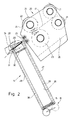
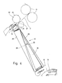
- the bands 10 are taken from a magazine 14 one after the other. This is arranged above the band drum 13, slightly offset from this, in an upright position.
- the magazine 14 is arranged at an acute angle of the longitudinal extent (longitudinal axis) to the vertical, that is to say inclined.
- the magazine forms a removal opening 15, which corresponds approximately to the inner cross section of the magazine 14 here.
- a blank removal member is movably arranged, namely an unwinder 16 of a known type.
- the blanks or banderoles 10 are inserted into the magazine 14 at the upper end of the magazine 14 - opposite the removal opening 15.
- the banderoles 10 are successively cut off from a material web 17, the width of which corresponds to the width of the rectangular banderoles 10.
- the material web 17 is continuously from deducted a circumferential bobbin 18, which is mounted in the transport plane of the material web 17 or the banderoles 10.
- the bobbin 18 extends in a plane approximately parallel to the longitudinal center plane of the packaging machine, with the axis of rotation transverse to it. As a result, the bobbin is accommodated in a space-saving manner.
- the material web 17 drawn off from the bobbin 18 runs in several loops over a compensating rocker 19 which is known in terms of its structure and function.
- the material web 17 then arrives in a separating and feeding unit 20.
- the individual banderoles 10 are separated from the material web by separating corresponding sections 17 manufactured.
- the separating and feeding unit 20 in the exemplary embodiment according to FIGS. 1 and 2 consists of a pair of pull rollers 21 for pulling the material web 17 from the reel 18.
- the material web 17 then reaches the area of a separating device, which here consists of a knife roller 22 and a counter roll 23.
- the knife roller 22 is provided with a plurality of separating knives 24 which are distributed at equal distances from one another on the circumference and which each make a separating cut when they strike the material web 17 passed between the knife roller 22 and the counter roller 23.
- four banderoles 10 are separated from the material web with one revolution of the knife roller 22.
- the banderoles 10 pass from the separating and feeding unit 20 directly into the adjacent magazine 14, at the conveying speed of the material web 17 or at an increased speed.
- Such an increase in the conveying speed of the banderoles 10 after the separation thereof is brought about in the exemplary embodiment of FIGS. 1 and 2 by accelerating rollers 25 which are arranged on the separating and feeding unit 20, to be precise at an appropriate distance from Knife roller 22 and counter roller 23 in such a way that the blank or the band 10 is grasped immediately after the separation and is fed into the magazine 14 at an increased speed.
- the described rollers 21, 22, 23, 25 of the separating and feeding unit are arranged on one or preferably two spaced-apart support cheeks 26, these being connected to one another in the lower part, so that the separating and feeding unit 20 forms a manageable unit .
- the magazine 14 is designed in a special way in the upper region. 5, the magazine 14 expediently has a C-shaped cross-sectional profile.
- the rectangular banderoles 10 are fed into the magazine 14 with their (imaginary) longitudinal axis pointing in the conveying direction, that is to say via a narrow side thereof.
- the conveying plane of the banderoles 10 predetermined by the separating and feeding unit 20 can be directed at an acute angle to the upper, open side of the magazine 14, such that the banderoles 10 are in a slightly downwardly directed conveying plane into the magazine 14 "which is open at the top. be shot ".
- the magazine 14 is designed or arranged so that the blanks or banderoles 10 abut against a stop on the side opposite the insertion side (side wall 27), which is formed here by the opposite side wall 28. This can expediently be provided with an elevation beyond the dimension given by the side wall 27 in order to ensure a sufficient stop for the introduced blanks.
- the banderoles 10 are accordingly fed into the magazine 14 via an upper insertion opening 29 in the embodiment according to FIGS. 1 and 2, namely by lateral, transverse-axial feeding.
- the incoming banderoles 10 are deposited on a stack 30 formed within the magazine 14.
- a lowering element for the banderoles 10 is arranged in this upper region of the magazine 14, namely a hold-down device 31 that can be moved up and down.
- this consists of a simple plate which enters the magazine 14 in the upper region of the magazine 14 via a slot-shaped opening in the side wall 28. 4 and 5, the hold-down device 31 consists of two fingers 32, 33, which are connected to one another outside the magazine 14 to form a fork-shaped structure.
- the hold-down device 31 detects the fed-in banderoles 10 on their upper side and conveys them downwards in the magazine 14.
- the hold-down device 31 can be moved in a special way, namely along an oval movement path 34.
- the hold-down device 31 in the fork-shaped configuration according to FIGS. 4 and 5 enters the magazine 14 via the open slots 35 in the region of a (wider) rear wall with the fingers 32, 33. After a band 10 has been deposited, the fingers 32, 33 are withdrawn from the magazine 14, so that the next band 10 can be inserted into the magazine 14 without a time delay. Outside of the magazine, the hold-down device 31 is moved back into an upper position and reinserted into the magazine 14 from above. The banderole 10 introduced into the magazine 14 during this return movement of the hold-down device 31 is then fed to the stack 30 by the subsequent downward movement of the hold-down device 31.
- the magazine 14 is open on a longer side, namely with a side opening 36 which extends over the full height. This is in the area of a longer side dimension of the magazine.
- the side opening 36 is chosen so wide that a (manual) intervention in the magazine 14 is possible, in particular to eliminate any incorrect stacking of the banderoles 10.
- a simplified feeding of the material web 17 via the pull rollers 21 and via the knife roller 22 with counter roller 23 is provided.
- the two latter rollers are mounted in the immediate vicinity, that is to say at a short distance, from the upper end region of the magazine 14.
- the cut bands 10 are inserted directly into the magazine 14 by knife roller 22 and counter roller 23.
- the knife roller 22 is provided with a larger number of cutting knives 24, so that a correspondingly larger number of banderoles 10 is produced per revolution.
- the magazine 14 is designed in the area of the entry of the banderoles 10 so that an insertion opening 37 is formed in the area of a side boundary (side wall) of the magazine 14.
- the relevant lateral boundary is set back in relation to an upper edge and in particular in relation to an opposite side wall 28, so that a free, upwardly open insertion opening 37 is created for the lateral insertion of the bands 10 into the magazine 14.
- this insertion opening 37 is formed in the region of a wider transverse dimension of the magazine.
- the rectangular, elongated banderoles 10 are separated from the material web 17 with a corresponding width in such a way that they point transversely to the conveying direction with the longitudinal extent.
- the banderoles 10 are accordingly separated from the material web 17 in landscape format and inserted into the magazine 14 in a corresponding relative position over the broad side, specifically here on the side opening 36 side.
- banderoles 17 Since the banderoles 17 must be removed from the magazine 14 on the underside in the longitudinal direction thereof, a reversing movement of the banderoles 10 is provided within the magazine 14 during the downward movement in this exemplary embodiment.
- the bands 10 are thus taken out in an insertion position relative to the upper 90 o staggered relative position by the dispenser 16 from the magazine.
- the magazine 14 is designed so that the side walls 27, 28 or side webs 38, 39 are helically wound to limit the side opening 36, such that in the upper area, in particular at the insertion opening 37, the larger size of the magazine (side port 36) the incoming bands faces 10, while the same side of the magazine is rotated by the "swirl" shape at the lower portion by 90 o. Since the stacked banderoles 10 are guided within the magazine during the step-wise downward movement through the side walls 27, 28 and the webs 38, 39, a corresponding rotational movement of the banderoles 10 in their plane results automatically.
- the magazine 14 can be filled in manual operation by inserting stacks of banderoles into the magazine 14, which is open at the top. No retrofitting is required for this.
- the banderoles 10 are produced and fed by separating them from the material web 17 independently of the (conventionally designed) magazine 14. Banderoles 10 produced in this way can be inserted in stacks.
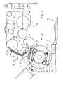
- the production and feeding of the blanks or banderoles 10 by separating them from the material web 17 takes place here by means of a separate banderole unit 40.
- the cutting unit 41 is immediately adjacent to the band drum 13 arranged in such a way that the separated banderoles 10 are picked up and conveyed directly from the banderole drum 13.
- the cutting unit consists of a rotating knife roller 42 and a fixed counter knife 43.
- the material web 17 coming from a bobbin forms a material loop 46 (sag) between the deflection rollers 44, 45 as a variable web store.
- the size of the material loop 46 is monitored, in the present case by optoelectric sensors 47. These control the drive of the deflection roller 44 and thus the feed of the material web 17.
- a horizontal conveyor section 48 of the material web 17 adjoins the deflection roller 45.
- the material web is scanned within the same, namely of precisely attached control marks of the same.
- a known optoelectric scanning element 49 is provided for this.
- the material web 17 runs at the end of the horizontal conveying section 48 via feed rollers 50, 51. These are driven very precisely, in such a way that the region of the material web 17 following in the conveying direction experiences a very exact feed.
- the feed rollers 50, 51 are preferably driven by a stepping motor (not shown), the movements of which are controlled by the scanning element 49 and thus in accordance with the control marks on the material web 17.
- the material web 17 is fed to the cutting unit 41 along a substantially downwardly directed conveyor section.
- the material web 17 is guided exactly, namely by a rigid web guide 52.
- This consists of two guide walls 53, 54 arranged at a short distance on both sides of the material web 17.
- the web guide 52 undergoes an arcuate change in direction such that a region of the material web 17 facing the band drum 13 or the cutting unit 41 is directed at an acute angle to the circumference of the band drum 13.
- the band drum 13 is provided with two diagonally opposite band holder 55, 56 in the present embodiment. These each consist of a bearing piece 57 for the banderole, which protrudes radially beyond the peripheral surface of the banderole drum 13. An outer contact surface of this contact piece 57 is designed in the form of an arc of a circle, concentric with the band drum 13.
- suction bores 58 open at the contact surface of the contact piece 57 and are connected to a central vacuum source via suction channels. The suction bores 58 are subjected to negative pressure when a banderole 10 is taken over and during the transport thereof.
- the banderole holder 55, 56 is assigned a mechanical holding member for grasping and holding an end region of the banderole 10 lying forward in the conveying direction.
- this is a clamping finger 59 with a slightly angled clamping end 60. This is in the clamping position on the area of the contact piece 57 lying forward in the direction of rotation of the band drum 13 while clamping the front end of the band 10.
- the clamping finger 59 is angled , Two-armed lever formed, which can be moved in the open position (shown in Fig. 6 and 7) and in the clamping position by pivoting.
- a free end of the clamping finger 59 runs with a feeler roller 61 on a suitably designed cam track 62.
- the opening and clamping positions are determined by the shape of the cam track 62.
- the cutting unit 41 is arranged directly adjacent to the circumference of the band drum 13, in such a way that the material web 17 reaches the band holder 55, 56 before the band 10 is cut off. Before the separating cut is made, the front end of the material web 17 is already fixed on the banderole holder 55, 56 by moving the clamping finger 59 into the clamping position. If the separating cut is carried out immediately thereafter, the band 10 is already held on the band drum 13.
- a glue unit 63 is arranged in such a way that a glue segment 64 transfers glue strips to the outwardly facing side of the band 10 when it rests on the band holder 55, 56, directly after the cutting unit 41.
Landscapes
- Engineering & Computer Science (AREA)
- Mechanical Engineering (AREA)
- Labeling Devices (AREA)
- Making Paper Articles (AREA)
Applications Claiming Priority (4)
| Application Number | Priority Date | Filing Date | Title |
|---|---|---|---|
| DE4006021 | 1990-02-26 | ||
| DE4006021 | 1990-02-26 | ||
| DE19904027247 DE4027247A1 (de) | 1990-02-26 | 1990-08-29 | Verfahren und vorrichtung zum foerdern von banderolen zwecks uebergabe an eine (zigaretten-)packung |
| DE4027247 | 1990-08-29 |
Publications (2)
| Publication Number | Publication Date |
|---|---|
| EP0444547A1 true EP0444547A1 (fr) | 1991-09-04 |
| EP0444547B1 EP0444547B1 (fr) | 1995-05-17 |
Family
ID=25890549
Family Applications (1)
| Application Number | Title | Priority Date | Filing Date |
|---|---|---|---|
| EP19910102639 Expired - Lifetime EP0444547B1 (fr) | 1990-02-26 | 1991-02-22 | Méthode et dispositif pour convoyer des bandes de fermeture en vue de les transférer à des paquets |
Country Status (5)
| Country | Link |
|---|---|
| US (1) | US5203953A (fr) |
| EP (1) | EP0444547B1 (fr) |
| JP (1) | JP3027206B2 (fr) |
| BR (1) | BR9100770A (fr) |
| DE (2) | DE4027247A1 (fr) |
Cited By (4)
| Publication number | Priority date | Publication date | Assignee | Title |
|---|---|---|---|---|
| DE19736388A1 (de) * | 1997-08-21 | 1999-02-25 | Focke & Co | Verfahren und Vorrichtung zum Transportieren von Banderolen oder dergleichen |
| WO2000035756A1 (fr) * | 1998-12-15 | 2000-06-22 | G.D S.P.A. | Procede de fabrication de paquets de cigarettes etanches et appareil correspondant |
| EP0842856B1 (fr) * | 1996-11-19 | 2004-05-26 | Focke & Co. (GmbH & Co.) | Procédé et dispositif pour la fabrication de banderoles et les appliquer sur des emballages (pour cigarettes) |
| EP4173977A3 (fr) * | 2021-10-07 | 2023-08-30 | Buhrs Packaging Solutions B.V. | Module d'emballage et procédé pour fournir un manchon autour d'un article de courrier |
Families Citing this family (22)
| Publication number | Priority date | Publication date | Assignee | Title |
|---|---|---|---|---|
| US5545286A (en) * | 1994-11-10 | 1996-08-13 | Smyth Systems Company | Rotary magazine system for labeler |
| DE19616871A1 (de) * | 1996-04-26 | 1997-10-30 | Focke & Co | Verpackung für Tabakwaren, insbesondere Zigaretten sowie Verfahren und Vorrichtung zum Herstellen derselben |
| IT1298380B1 (it) * | 1997-12-22 | 2000-01-05 | Gd Spa | Metodo per l'applicazione di fascette a pacchetti sostanzialmente parallelepipedi. |
| DE19805697A1 (de) * | 1998-02-06 | 1999-08-12 | Topack Verpacktech Gmbh | Vorrichtung zum Abziehen und Überführen flexibler streifenförmiger Gegenstände von der Unterseite eines Magazins zu einem anschließenden Transportmittel |
| IT1299982B1 (it) * | 1998-04-22 | 2000-04-04 | Gd Spa | Metodo per la realizzazione di pacchetti di sigarette ed impianto per l'attuazione di tale metodo. |
| SI0960831T1 (en) | 1998-05-26 | 2002-04-30 | Philip Morris Products S.A. | Package comprising a coupon and process for obtaining said package |
| DE10019438A1 (de) * | 2000-04-19 | 2001-10-25 | Meto International Gmbh | Vorrichtung und Verfahren zum Anbringen eines Sicherungselementes für die elektronische Artikelsicherung auf einem Etikett |
| ITBO20000517A1 (it) * | 2000-09-07 | 2002-03-07 | Gd Spa | Metodo ed unita' di applicazione di etichette |
| DE10056403A1 (de) * | 2000-11-14 | 2002-05-23 | Topack Verpacktech Gmbh | Verfahren und Vorrichtung zum Überführen eines Flächengebildes |
| DE10056407A1 (de) * | 2000-11-14 | 2002-05-23 | Topack Verpacktech Gmbh | Einrichtung und Verfahren zum Überführen eines Flächengebildes |
| ITBO20010360A1 (it) | 2001-06-06 | 2002-12-06 | Gd Spa | Unita' per l'applicazione di tagliandi a pacchetti in macchine confezionatrici |
| DE10257598A1 (de) | 2002-12-09 | 2004-06-24 | Focke Gmbh & Co. Kg | Verfahren und Vorrichtung zur Handhabung von Zuschnitten, insbesondere Coupons |
| ITBO20030184A1 (it) * | 2003-04-01 | 2004-10-02 | Gd Spa | Metodo e macchina per realizzare un incarto di articoli |
| ITBO20030768A1 (it) * | 2003-12-22 | 2005-06-23 | Gd Spa | Metodo e macchina per la realizzazione di una confezione |
| ITBO20040589A1 (it) * | 2004-09-22 | 2004-12-22 | Gd Spa | Metodo e unita' per applicare un'etichetta ad un articolo |
| NL1028338C2 (nl) * | 2005-02-18 | 2006-08-21 | Antonius Adrianus Arnold Smits | Inrichting en werkwijze voor het aanbrengen van voorwerpen op produkten. |
| DE102009040918A1 (de) * | 2009-09-11 | 2011-03-17 | Focke & Co.(Gmbh & Co. Kg) | Vorrichtung und Verfahren zum Handhaben von Stapeln aus Druckträgern |
| DE102012001723A1 (de) * | 2012-01-31 | 2013-08-01 | Khs Gmbh | Etikettieraggregat, Vorrichtung zum Etikettieren von Behältern mit einem solchen Etikettieraggregat sowie Verfahren zum Betrieb des Etikettieraggregates oder der Vorrichtung |
| DE202014100204U1 (de) * | 2014-01-20 | 2015-04-22 | Krones Ag | Bandpuffer für Etikettenbänder |
| CN107187106B (zh) * | 2017-05-15 | 2019-02-26 | 遵义市兴英鹏塑料包装有限公司 | 一种牛皮袋粘接装置 |
| CN107775726A (zh) * | 2017-11-17 | 2018-03-09 | 青岛海威物联科技有限公司 | 一种电子标签裁切设备 |
| DE102017222643A1 (de) * | 2017-12-13 | 2019-06-13 | Koenig & Bauer Ag | Bogenverarbeitende Maschine |
Citations (4)
| Publication number | Priority date | Publication date | Assignee | Title |
|---|---|---|---|---|
| DE1249889B (de) * | 1967-09-14 | MABEG Maschinenbau GmbH, Offenbach/M | Vorrichtung zum kontinuierlichen Vereinzeln von Bogen | |
| DE1586399A1 (de) * | 1967-05-24 | 1970-04-23 | Strunck & Co Maschf H | Verfahren und Vorrichtung zum Anbringen von Umhuellungen,Etiketten od.dgl. an Gegenstaenden |
| EP0078076A2 (fr) * | 1978-12-05 | 1983-05-04 | Associpak International Inc. | Cisaille pour bandes |
| GB2111941A (en) * | 1981-12-22 | 1983-07-13 | Gd Spa | A feed device for labels |
Family Cites Families (18)
| Publication number | Priority date | Publication date | Assignee | Title |
|---|---|---|---|---|
| US2018373A (en) * | 1933-05-02 | 1935-10-22 | Internat Banding Machine Compa | Band, stamp, or label magazine and handling mechanism |
| FR2151733A5 (fr) * | 1971-09-10 | 1973-04-20 | Kronseder Hermann | |
| BE791462A (fr) * | 1971-12-04 | 1973-03-16 | Jagenberg Werke Ag | Machine a etiqueter pour bouteilles ou objets similaires, avec un dispositif pour en enrober d'une feuille metallique les goulots oules tetes |
| JPS539079B2 (fr) * | 1974-11-07 | 1978-04-03 | ||
| US4029537A (en) * | 1975-12-08 | 1977-06-14 | Pitney-Bowes, Inc. | Label applicator |
| DE2745866C3 (de) * | 1977-10-12 | 1980-07-17 | Jagenberg-Werke Ag, 4000 Duesseldorf | Querschneider |
| DE2913538C2 (de) * | 1979-04-04 | 1983-04-07 | Jagenberg-Werke AG, 4000 Düsseldorf | Etikettierstation für Gegenstände, wie Flaschen |
| DE3305608C2 (de) * | 1983-02-18 | 1984-12-13 | Hans 8901 Kissing Einlehner | Gerät zur Sicherung von Schriftstücken, insbesondere Wettscheinen, vor Fälschungen |
| DE3339555A1 (de) * | 1983-11-02 | 1985-05-09 | Maschinenfabrik Alfred Schmermund Gmbh & Co, 5820 Gevelsberg | Vorrichtung zum anbringen von siegelmarken an zigarettenpackungen |
| IT1179984B (it) * | 1984-02-17 | 1987-09-23 | Cavagnino & Gatti Spa | Dispositivo per la presa ed il trasferimento delle etichette in una macchina etichettatrice per bottiglie e simili |
| US4589943A (en) * | 1984-03-08 | 1986-05-20 | American Bank Note Company | Apparatus and procedure for applying adhesive labels |
| US4647333A (en) * | 1984-10-02 | 1987-03-03 | New Jersey Machine Inc. | Combination labeling and literature applying machine |
| US4680023A (en) * | 1985-04-19 | 1987-07-14 | Sherwood Tool, Incorporated | Container forming apparatus having in-line blanker |
| FR2581029B1 (fr) * | 1985-04-24 | 1987-05-29 | Smh Alcatel | Distributeur d'etiquettes et machine a affranchir equipee de ce distributeur |
| JP2525586B2 (ja) * | 1986-12-19 | 1996-08-21 | 澁谷工業 株式会社 | カ−トン取出し装置 |
| JPH0242729A (ja) * | 1988-08-02 | 1990-02-13 | Nec Corp | アルミニウム系薄膜配線 |
| JPH0246446A (ja) * | 1988-08-08 | 1990-02-15 | Fuji Photo Film Co Ltd | ハロゲン化銀カラー写真感光材料の処理方法 |
| US5009740A (en) * | 1989-08-09 | 1991-04-23 | Nippon Flute Co., Ltd. | Bag making machine |
-
1990
- 1990-08-29 DE DE19904027247 patent/DE4027247A1/de not_active Withdrawn
-
1991
- 1991-02-22 EP EP19910102639 patent/EP0444547B1/fr not_active Expired - Lifetime
- 1991-02-22 DE DE59105480T patent/DE59105480D1/de not_active Expired - Fee Related
- 1991-02-26 US US07/660,827 patent/US5203953A/en not_active Expired - Lifetime
- 1991-02-26 JP JP3100291A patent/JP3027206B2/ja not_active Expired - Fee Related
- 1991-02-26 BR BR9100770A patent/BR9100770A/pt unknown
Patent Citations (4)
| Publication number | Priority date | Publication date | Assignee | Title |
|---|---|---|---|---|
| DE1249889B (de) * | 1967-09-14 | MABEG Maschinenbau GmbH, Offenbach/M | Vorrichtung zum kontinuierlichen Vereinzeln von Bogen | |
| DE1586399A1 (de) * | 1967-05-24 | 1970-04-23 | Strunck & Co Maschf H | Verfahren und Vorrichtung zum Anbringen von Umhuellungen,Etiketten od.dgl. an Gegenstaenden |
| EP0078076A2 (fr) * | 1978-12-05 | 1983-05-04 | Associpak International Inc. | Cisaille pour bandes |
| GB2111941A (en) * | 1981-12-22 | 1983-07-13 | Gd Spa | A feed device for labels |
Cited By (7)
| Publication number | Priority date | Publication date | Assignee | Title |
|---|---|---|---|---|
| EP0842856B1 (fr) * | 1996-11-19 | 2004-05-26 | Focke & Co. (GmbH & Co.) | Procédé et dispositif pour la fabrication de banderoles et les appliquer sur des emballages (pour cigarettes) |
| DE19736388A1 (de) * | 1997-08-21 | 1999-02-25 | Focke & Co | Verfahren und Vorrichtung zum Transportieren von Banderolen oder dergleichen |
| US6050320A (en) * | 1997-08-21 | 2000-04-18 | Focke & Co. (Gmbh & Co.) | Method and device for gluing material webs, band labels or the like |
| WO2000035756A1 (fr) * | 1998-12-15 | 2000-06-22 | G.D S.P.A. | Procede de fabrication de paquets de cigarettes etanches et appareil correspondant |
| US6684606B1 (en) | 1998-12-15 | 2004-02-03 | G.D. S.P.A. | Method and apparatus for manufacturing sealed packets of cigarettes |
| EP4173977A3 (fr) * | 2021-10-07 | 2023-08-30 | Buhrs Packaging Solutions B.V. | Module d'emballage et procédé pour fournir un manchon autour d'un article de courrier |
| US12162637B2 (en) | 2021-10-07 | 2024-12-10 | Buhrs Packaging Solutions B.V. | Wrapping module and a method for providing a sleeve around a mail item |
Also Published As
| Publication number | Publication date |
|---|---|
| DE59105480D1 (de) | 1995-06-22 |
| BR9100770A (pt) | 1991-10-29 |
| EP0444547B1 (fr) | 1995-05-17 |
| US5203953A (en) | 1993-04-20 |
| DE4027247A1 (de) | 1991-08-29 |
| JPH04215933A (ja) | 1992-08-06 |
| JP3027206B2 (ja) | 2000-03-27 |
Similar Documents
| Publication | Publication Date | Title |
|---|---|---|
| EP0444547B1 (fr) | Méthode et dispositif pour convoyer des bandes de fermeture en vue de les transférer à des paquets | |
| EP0258597B1 (fr) | Dispositif pour alimenter en ébauches une machine d'emballage | |
| EP0312877B1 (fr) | Procédé et dispositif pour fabriquer et convoyer des coupes pour paquets | |
| DE3018894C2 (de) | Einrichtung zum Bilden von hochkant stehenden Paketen flacher Faltschachtelzuschnitte | |
| DE3038058C2 (de) | Einrichtung zur Bildung von Zuschnittspaketen | |
| DE3937995C2 (de) | Verfahren und Vorrichtung zur Bogenriesvereinzelung und zur Riesablage | |
| DE2332988A1 (de) | Verfahren und vorrichtung zum entladen und stapeln von gegenstaenden, insbesondere von ziegeln | |
| DD239181A5 (de) | Vorrichtung zum zufuehren von zigaretten zu einer verpackungsstation | |
| EP0987179B1 (fr) | Procédé et installation pour transférer des emballages à une station d'empilage | |
| DE4224010A1 (de) | Vorrichtung zum handhaben von bahn- oder bogenmaterial aus papier | |
| DE3330681C2 (fr) | ||
| EP0243944B1 (fr) | Dispositif pour fabriquer des paquets ou des piles de feuilles de papier pliées | |
| CH692700A5 (de) | Zusammentragmaschine. | |
| DE4237937C2 (de) | Vorrichtung zum Transport von Zuschnittstapeln | |
| EP0514783B1 (fr) | Dispositif pour transporter des piles de feuilles en papier | |
| EP0591099B1 (fr) | Procédé et dispositif pour fabriquer des piles de produits en papier liées | |
| DE69607698T2 (de) | Vorrichtung zum Be- und/oder Entladen von einem Behälter mit Stapeln von Packungen, insbesondere Eierkartons | |
| EP0451091B1 (fr) | Margeur | |
| EP0529204A1 (fr) | Appareil pour transférer des plaques vers une machine de thermoformage | |
| EP1593626B1 (fr) | Margeur du bord avant | |
| DE102005002532A1 (de) | Vorrichtung und Verfahren zum automatisierten und zeitgleichen Bereitstellen und Wechseln von mindestens zwei Rollen aus Papierbahnen oder dergleichen für einen nachgeordneten Formatschneider | |
| EP0680913A1 (fr) | Procédé et dispositif pour accumuler des flancs | |
| EP1593633B1 (fr) | Dispositif pour empiler des articles imprimés | |
| EP3323745B1 (fr) | Machine de traitement de récipients et procédé de traitement de récipients | |
| DE4210749C2 (de) | Vorrichtung zum Einbringen von Beutelpackungen in einen Sammelbehälter |
Legal Events
| Date | Code | Title | Description |
|---|---|---|---|
| PUAI | Public reference made under article 153(3) epc to a published international application that has entered the european phase |
Free format text: ORIGINAL CODE: 0009012 |
|
| AK | Designated contracting states |
Kind code of ref document: A1 Designated state(s): DE FR GB IT |
|
| 17P | Request for examination filed |
Effective date: 19920229 |
|
| 17Q | First examination report despatched |
Effective date: 19930107 |
|
| ITF | It: translation for a ep patent filed | ||
| GRAA | (expected) grant |
Free format text: ORIGINAL CODE: 0009210 |
|
| AK | Designated contracting states |
Kind code of ref document: B1 Designated state(s): DE FR GB IT |
|
| GBT | Gb: translation of ep patent filed (gb section 77(6)(a)/1977) |
Effective date: 19950522 |
|
| REF | Corresponds to: |
Ref document number: 59105480 Country of ref document: DE Date of ref document: 19950622 |
|
| ET | Fr: translation filed | ||
| PLBE | No opposition filed within time limit |
Free format text: ORIGINAL CODE: 0009261 |
|
| STAA | Information on the status of an ep patent application or granted ep patent |
Free format text: STATUS: NO OPPOSITION FILED WITHIN TIME LIMIT |
|
| 26N | No opposition filed | ||
| REG | Reference to a national code |
Ref country code: GB Ref legal event code: IF02 |
|
| PGFP | Annual fee paid to national office [announced via postgrant information from national office to epo] |
Ref country code: FR Payment date: 20060220 Year of fee payment: 16 |
|
| REG | Reference to a national code |
Ref country code: FR Ref legal event code: ST Effective date: 20071030 |
|
| PG25 | Lapsed in a contracting state [announced via postgrant information from national office to epo] |
Ref country code: FR Free format text: LAPSE BECAUSE OF NON-PAYMENT OF DUE FEES Effective date: 20070228 |
|
| PGFP | Annual fee paid to national office [announced via postgrant information from national office to epo] |
Ref country code: DE Payment date: 20090219 Year of fee payment: 19 |
|
| PGFP | Annual fee paid to national office [announced via postgrant information from national office to epo] |
Ref country code: GB Payment date: 20090217 Year of fee payment: 19 |
|
| PGFP | Annual fee paid to national office [announced via postgrant information from national office to epo] |
Ref country code: IT Payment date: 20090218 Year of fee payment: 19 |
|
| GBPC | Gb: european patent ceased through non-payment of renewal fee |
Effective date: 20100222 |
|
| PG25 | Lapsed in a contracting state [announced via postgrant information from national office to epo] |
Ref country code: DE Free format text: LAPSE BECAUSE OF NON-PAYMENT OF DUE FEES Effective date: 20100901 |
|
| PG25 | Lapsed in a contracting state [announced via postgrant information from national office to epo] |
Ref country code: GB Free format text: LAPSE BECAUSE OF NON-PAYMENT OF DUE FEES Effective date: 20100222 Ref country code: IT Free format text: LAPSE BECAUSE OF NON-PAYMENT OF DUE FEES Effective date: 20100222 |