EP0444552A2 - Fixing bracket for a curtain wall mounting-device system - Google Patents
Fixing bracket for a curtain wall mounting-device system Download PDFInfo
- Publication number
- EP0444552A2 EP0444552A2 EP91102687A EP91102687A EP0444552A2 EP 0444552 A2 EP0444552 A2 EP 0444552A2 EP 91102687 A EP91102687 A EP 91102687A EP 91102687 A EP91102687 A EP 91102687A EP 0444552 A2 EP0444552 A2 EP 0444552A2
- Authority
- EP
- European Patent Office
- Prior art keywords
- plate
- leg
- plates
- wall
- longitudinal direction
- Prior art date
- Legal status (The legal status is an assumption and is not a legal conclusion. Google has not performed a legal analysis and makes no representation as to the accuracy of the status listed.)
- Granted
Links
Images



Classifications
-
- E—FIXED CONSTRUCTIONS
- E04—BUILDING
- E04B—GENERAL BUILDING CONSTRUCTIONS; WALLS, e.g. PARTITIONS; ROOFS; FLOORS; CEILINGS; INSULATION OR OTHER PROTECTION OF BUILDINGS
- E04B2/00—Walls, e.g. partitions, for buildings; Wall construction with regard to insulation; Connections specially adapted to walls
- E04B2/88—Curtain walls
- E04B2/96—Curtain walls comprising panels attached to the structure through mullions or transoms
Definitions
- the invention relates to a mounting bracket according to the preamble of claim 1.
- Such brackets are used for anchoring post profiles for holding curtain wall parts and for anchoring post profiles between two ceiling panels of a building.
- the facade parts to be fastened are prefabricated by the facade builder, but must be assembled to form a facade on the construction site itself. During assembly, the dimensional deviations due to the tolerances permitted by DIN 4172 must be taken into account. Prefabrication of the facades is therefore only possible if the add-on parts allow the building-side tolerances to be compensated.
- the attachments have to accommodate dilatations resulting from temperature changes, which is why it is necessary to design a facade fastening system as a system of interacting fixed and floating bearings. If such a system consists of several mounting brackets, a certain proportion of the brackets used must be designed as a fixed bearing and the rest as a floating bearing.
- a console which consists of a U-shaped mounting rail part and a spacer with two parallel cheeks, in which the U-legs of the mounting rail are pushed over the cheeks of the spacer. Agraffes are also mounted on the two cheeks, which engage behind a guide part located on the mounting rail with a rear engagement part, so that the mounting rail can be displaced in its longitudinal direction parallel to the cheek surfaces.
- the disadvantage of this design is that different brackets are used as fixed and floating bearings. Furthermore, vertical adjustment of such a console is very difficult in the final assembly state.
- Another serious disadvantage of this console is the problematic assembly of elements and post-and-beam structures in the area of wall aprons, wall parapets etc. The installation space required to push the mounting rail onto the cheeks of the spacer is often not available. In such a case, the installation can only be realized by moving the attachment point of the console, which is time-consuming and therefore costly.
- the invention has for its object to realize a facade fastening system from several identical consoles for receiving post profiles such that there is a three-dimensional displaceability of the consoles used to compensate for building tolerances, that the consoles can be used both as a fixed bearing and as a floating bearing and that the facade fastening system can be assembled in the smallest of spaces during final assembly at the construction site and absorbs the dilatations that occur in the final assembly state.
- the wall plate is preferably attached to the building on a wall or ceiling using anchor rails, dowels or anchor plates. Compensation for any mounting tolerances of the wall plate is achieved either by moving the fastening elements located in the anchor rails or by appropriately designing the fastening point.
- the fastening point on the wall plate as an elongated hole extending in the transverse direction of the wall plate, it is possible, for example, to move the wall plate relative to a bolt protruding from the wall.
- each of the two leg plates are pushed in the direction of the longitudinal axis of the wall plate with guide rails located on them in groove-like recesses in the wall plate.
- each of the two leg plates can slide with their nose-like guide rail in the manner of a sliding guide in the respective groove-like recess of the wall plate. This possibility of sliding is used when using the device as a floating bearing to accommodate the dilatations that occur.
- a leg plate with its guide rail is first pushed into the groove-like recess of the wall plate.
- the single or multi-part post profile is inserted and only then is the second leg plate installed.
- the cohesion of the construction is ensured by the retaining bolt inserted in the transverse direction.
- the inserted post profile is adjusted in the longitudinal direction and held in its final assembly position by means of an adjusting screw which is effective in the longitudinal direction.
- the device is used as a fixed bearing.
- additional securing bolts preferably screws, are additionally inserted through the outer sides of the projections and the guide rail in the transverse direction perpendicular to the longitudinal direction. These protrude into a through hole running in the longitudinal direction in the guide rails.
- the device is used as a floating bearing, the openings and the securing bolts are omitted, and the set screw is not preloaded. Rather, the set screw has a play of preferably 5 mm relative to the head sides of the projections, as a result of which the absorption of the dilatations is ensured.
- the combination of the wall plate with an angle plate described in claims 10 and 11 is used to mount post profiles between the ceiling panels of a building, in which the brackets are not mounted next to each other, as in the case of continuous post profiles in the case of curtain walls, but opposite one another.
- This embodiment is therefore suitable for fastening post profiles between ceiling panels on the one hand and as a connection for an otherwise continuous facade in front of the ceiling panels.
- the embodiment of the openings in the leg plates as an elongated hole extending from the mounting end to the free end thereof allows the post profile to be adjusted in the direction of the wall plate or in the opposite direction away from the latter.
- the three-dimensional adjustability of the device is thus given.
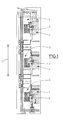
- the facade fastening system shown in Fig. 1 shows three fastening brackets 2 directly connected to the wall 1, in which continuous post profiles 3 are fixed. 2 shows two brackets 2, each of which is mounted via an angle plate 4 between two ceiling plates 5 and connected to a post profile 3.
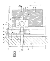
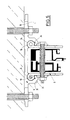
- FIG. 3 and 4 show the detailed structure of the console 2, the drawing plane of FIG. 3 running equally to the longitudinal direction 6 and the drawing plane of FIG. 4 being perpendicular to the drawing plane of FIG. 3 and the same to the transverse direction 7 and the direction of repulsion ( 15) runs.
- the console itself consists essentially of a wall plate 8 and two leg plates 9.
- the wall plate 8 is fastened with two fastening nuts 10 to two anchor pins 11 protruding from the wall 1. These anchor pins 11 pass through the wall plate 8 in two wall plate slots 12, both of which lie on the wall plate transverse axis and are cut by it. If the anchor pins 11 are already inserted, the wall plate 8 can be displaced in the two wall plate elongated holes relative to the wall 1 in the transverse direction 7 running parallel to its wall plate transverse axis. In the final assembly state, the wall plate 8 faces the wall 1 with its wall end face 13 and faces away from its free side 14, the wall end face 13 partially resting firmly against the wall 1.
- the post profile 3 lies perpendicular to the wall, with its longitudinal axis at right angles to the longitudinal direction 6 as well as to the transverse direction 7, extending in its stepping direction 15, between the leg plates 9.
- the leg plate outer sides 16 each have at the assembly ends 17 of the leg plates 9 a C-shaped guide rail 18 with the same cross-section to the transverse direction 7.
- the guide rail 18 has a longitudinal opening 6 on its head side 19, which limits it in the longitudinal direction 6, into which passage opening 20 extends an adjusting thread 21 is formed.
- the receiving groove 24 has a C-shaped cross-section which is the same as the transverse direction 7 and serves as a guide groove for the guide rails 18 located on the leg plates 9, which comprises them in the manner of a claw.
- the leg plates 9 are inserted with their guide rails 18 on a groove collar 25 into the receiving grooves 24 extending in the longitudinal direction 6 over the entire length of the wall plate 26 in the longitudinal direction 6.
- the guide rails 18 sliding in the longitudinal direction 6 in the receiving grooves 24 are secured in the longitudinal direction 6 by an adjusting screw 27 screwed into the adjusting thread 21 formed on the head side 19.
- the adjusting screw head 28 is supported on the groove collar 25 of the receiving groove 24 via a support disk 29 which absorbs the forces acting in the longitudinal direction 6 when the bracket 2 is to act as a fixed bearing in the facade fastening system.
- the outer flank 30 of the projections 22 is preferably designed as an Allen screw, approximately in the direction of the bisector 32 of the transverse direction 7 and the direction of repulsion 15 introduced to the wall 1 securing bolt 31 such that it passes through the outer flanks 30 of the receiving grooves 24 and the guide plates 18 in an alignment line 33 corresponding to its direction.
- the securing bolt 31 is an additional securing of the fixed bearing. If the bracket 2 acts as a floating bearing in the facade fastening system, there is preferably a play of 5 mm between the adjusting screw head 28 and the groove collar 25. The securing bolt 31 is not required for the floating bearing without replacement.
- Fig. 5 shows a special embodiment of the guide rails 18 on the one hand and the corresponding grooves 24 on the other.
- beads 34 pointing in the transverse direction 7 and extending in the longitudinal direction 6 are formed in the receiving grooves 24, which beads are filled with fixing projections 35 protruding from the guide rails 18 in the transverse direction 7 when the guide rails 18 are inserted.
- This combination of the beads 34 and the fixing projections 35 has the effect that the position of the leg plate ends 36 facing away from the mounting ends 17 in the direction of separation 15 cannot be changed in the transverse direction 7.
- This anti-twist device comes into play above all when the brackets 2 are still to be described.
- the post profile 3 is in the direction of repulsion 15 inserted into the free side 14 of the wall plate 8.
- the leg plates 9 are each broken approximately in the middle between the mounting end 17 and the leg plate free end 36 by a leg plate elongated hole 39 which extends in the direction 15 and which is located in the longitudinal direction approximately in the upper third of the leg plate facing the head side 19 of the guide rail 18.
- the post profile 3 is completely penetrated in the transverse direction 7 by a transverse bore 40 into which a transverse sleeve 41 is introduced.
- the post profile 3 is fixed in the hollow cross section 38 in such a way that a retaining screw running in the direction of its central longitudinal axis 50 parallel to the transverse direction 7 42 penetrates the leg plate elongated holes 39 and the transverse sleeve 41 lying in the transverse bore 40 in the transverse direction 7.
- additional holding plates 43 are mounted on the outside of the leg plate.
- the respective active surface 44 of the holding plate 43 facing the respective outer side of the leg plate 16 is profiled like a tooth surface.
- tooth ribs 45 protrude from the outside of the side plates 16 and extend in the longitudinal direction parallel to the wall 1 over the entire outside of the side plates. Tooth troughs 46 run parallel to the tooth ribs 45.
- the tooth surfaces on the outer side of the leg plate 16 and the respective active surfaces 44 of the holding plates 43 facing them are designed as mirror images of one another.
- the tooth surface-like leg plate outer sides 16 and the active surfaces 44 engage in the manner of a meshing pair of gears, with a toothed rib 45 in each case lying in a tooth valley 46 corresponding to it. If the leg plate outer sides 16 and the active surfaces 44 are in such engagement, they can no longer be displaced relative to one another in the direction of repulsion 15.
- the clamping surfaces 47 which run identically to the active surfaces 44, are present on the holding plates 43.
- the holding plates 43 are pierced by a through hole 48 which extends from the clamping surfaces 47 to the active surfaces 44. In the assembled state, the through bore 48 runs parallel to the transverse direction 7.
- the retaining plates 43 are penetrated by the retaining screw 42 in their through bores 48 in the final assembly state such that the through bores 48 of the retaining plates 43, the leg plate elongated holes 39 and the transverse bore 40 of the post profile 3 are aligned with one another in the direction of the central longitudinal axis 50 of the retaining screw 42 running parallel to the transverse direction 7 run.
Landscapes
- Engineering & Computer Science (AREA)
- Architecture (AREA)
- Physics & Mathematics (AREA)
- Electromagnetism (AREA)
- Civil Engineering (AREA)
- Structural Engineering (AREA)
- Load-Bearing And Curtain Walls (AREA)
- Connection Of Plates (AREA)
- Finishing Walls (AREA)
- Mutual Connection Of Rods And Tubes (AREA)
- Joining Of Building Structures In Genera (AREA)
- Clamps And Clips (AREA)
Abstract
Fassadenbefestigungssystem aus mehreren baugleichen Befestigungskonsolen (2), die sowohl als Fest- als auch als Loslager wirken können, die mit einer Wand (1) oder einer Deckenplatte (5) verbunden sind und an ihrer Freiseite (14) Pfostenprofile (3) in mindestens einer Richtung verschiebbar aufnehmen. Eine einzelne derartige Befestigungskonsole (2) besteht im wesentlichen aus einer Wandplatte (8) und zwei aus dieser senkrecht hervorstehenden Schenkelplatten (9), welche zwischen sich das Pfostenprofil (3) fixieren. Die Schenkelplatten (9) sind mit ihren Führungsschienen (18), die in den Aufnahmenuten (24) gleiten, mit der Wandplatte (8) verbunden. Die Lage der Schenkelplatten (9) wird in Längsrichtung (6) über die Stellschrauben (27) justiert. Das Pfostenprofil (3) wird zwischen den Schenkelplatten (9) über Halteplatten (43) in seiner Lage gesichert und über eine Halteschraube (42) mit diesen verbunden.
Description
Die Erfindung betrifft eine Befestigungskonsole gemäß Oberbegriff des Anspruchs 1. Derartige Konsolen dienen zur Verankerung von Pfostenprofilen für die Halterung vorgehängter Fassadenteile und zur Verankerung von Pfostenprofilen zwischen zwei Deckenplatten eines Gebäudes. Die zu befestigenden Fassadenteile werden beim Fassadenbauer vorgefertigt, müssen jedoch auf der Baustelle selbst zu einer Fassade zusammenmontiert werden. Bei der Montage müssen die Maßabweichungen aufgrund der nach DIN 4172 zulässigen Toleranzen berücksichtigt werden. Eine Vorfertigung der Fassaden ist daher nur möglich, wenn die Anbauteile es zulassen, die gebäudeseitigen Toleranzen auszugleichen. Ferner müssen die Anbauteile aus Temperaturänderungen resultierende Dilatationen aufnehmen, weshalb es notwendig ist, ein Fassadenbefestigungssystem als ein System von zusammenwirkenden Fest- und Loslagern auszulegen. Besteht ein derartiges System aus mehreren Befestigungskonsolen, muß ein gewisser Anteil der verwendeten Konsolen als Festlager und der Rest als Loslager ausgelegt werden.The invention relates to a mounting bracket according to the preamble of
Aus DE 30 32 359 C2 ist eine Konsole bekannt, die aus einem U-förmigen Tragschienenteil und einem Distanzhalter mit zwei parallelen Wangen besteht, bei der die U-Schenkel der Tragschiene über die Wangen des Distanzhalters geschoben werden. An den beiden Wangen sind weiterhin Agraffen montiert, die ein auf der Tragschiene befindliches Führungsteil mit einem Hintergreifteil hintergreifen, so daß die Tragschiene in ihrer Längsrichtung parallel zu den Wangenflächen verschiebbar ist. Nachteilig ist bei dieser Konstruktion, daß unterschiedliche Konsolen als Fest- und Loslager eingesetzt werden. Ferner ist im Endmontagezustand eine Vertikalverstellung einer derartigen Konsole nur sehr schwer möglich. Ein weiterer gravierender Nachteil dieser Konsole liegt in der problematischen Montage von Elementen und von Pfosten-Riegel-Konstruktionen im Bereich von Mauerschürzen, Mauerbrüstungen etc. Hierbei steht der zum Aufschieben der Tragschiene auf die Wangen des Distanzhalters notwendige Einbauraum häufig nicht zu Verfügung. Der Einbau kann in einem derartigen Fall nur durch eine Verlegung des Befestigungspunktes der Konsole realisiert werden, welche zeit- und damit kostenintensiv ist.From DE 30 32 359 C2 a console is known which consists of a U-shaped mounting rail part and a spacer with two parallel cheeks, in which the U-legs of the mounting rail are pushed over the cheeks of the spacer. Agraffes are also mounted on the two cheeks, which engage behind a guide part located on the mounting rail with a rear engagement part, so that the mounting rail can be displaced in its longitudinal direction parallel to the cheek surfaces. The disadvantage of this design is that different brackets are used as fixed and floating bearings. Furthermore, vertical adjustment of such a console is very difficult in the final assembly state. Another serious disadvantage of this console is the problematic assembly of elements and post-and-beam structures in the area of wall aprons, wall parapets etc. The installation space required to push the mounting rail onto the cheeks of the spacer is often not available. In such a case, the installation can only be realized by moving the attachment point of the console, which is time-consuming and therefore costly.
Der Erfindung liegt die Aufgabe zugrunde, ein Fassadenbefestigungssystem aus mehreren baugleichen Konsolen zur Aufnahme von Pfostenprofilen derart zu realisieren, daß eine zum Ausgleich von Gebäudetoleranzen dienende dreidimensionale Verschiebbarkeit der Konsolen gegeben ist, daß die Konsolen sowohl als Festlager als auch als Loslager eingesetzt werden können und daß das Fassadenbefestigungssystem auf engstem Raum bei der Endmontage auf der Baustelle zusammengesetzt werden kann und die im Montageendzustand auftretenden Dilatationen aufnimmt.The invention has for its object to realize a facade fastening system from several identical consoles for receiving post profiles such that there is a three-dimensional displaceability of the consoles used to compensate for building tolerances, that the consoles can be used both as a fixed bearing and as a floating bearing and that the facade fastening system can be assembled in the smallest of spaces during final assembly at the construction site and absorbs the dilatations that occur in the final assembly state.
Diese Aufgabe wird durch die kennzeichnenden Merkmale des Anspruchs 1 gelöst.This object is achieved by the characterizing features of
Die Befestigung der Wandplatte am Gebäude an einer Wand oder Decke erfolgt vorzugsweise mittels Ankerschienen, Dübeln oder Ankerplatten. Der Ausgleich etwaiger Montagetoleranzen der Wandplatte erfolgt entweder durch eine Verschiebung der in den Ankerschienen befindlichen Befestigungselemente oder durch eine entsprechende Ausgestaltung des Befestigungspunktes. Durch eine Ausgestaltung des Befestigungspunktes an der Wandplatte als sich in Querrichtung der Wandplatte erstreckendes Langloch ist es beispielsweise möglich, die Wandplatte relativ zu einem aus der Wand herausstehenden Bolzen zu bewegen.The wall plate is preferably attached to the building on a wall or ceiling using anchor rails, dowels or anchor plates. Compensation for any mounting tolerances of the wall plate is achieved either by moving the fastening elements located in the anchor rails or by appropriately designing the fastening point. By designing the fastening point on the wall plate as an elongated hole extending in the transverse direction of the wall plate, it is possible, for example, to move the wall plate relative to a bolt protruding from the wall.
Es werden zwei Schenkelplatten in Richtung der Längsachse der Wandplatte mit an ihnen befindlichen Führungsschienen in nutartige Ausnehmungen der Wandplatte geschoben. Im Montageendzustand kann jede der beiden Schenkelplatten mit ihrer nasenartigen Führungsschiene nach Art einer Gleitführung in der jeweiligen nutartigen Ausnehmung der Wandplatte gleiten. Diese Gleitmöglichkeit wird beim Einsatz der Vorrichtung als Loslager zur Aufnahme der auftretenden Dilatationen genutzt.Two leg plates are pushed in the direction of the longitudinal axis of the wall plate with guide rails located on them in groove-like recesses in the wall plate. In the final assembly state, each of the two leg plates can slide with their nose-like guide rail in the manner of a sliding guide in the respective groove-like recess of the wall plate. This possibility of sliding is used when using the device as a floating bearing to accommodate the dilatations that occur.
Bei der Montage wird zunächst eine Schenkelplatte mit ihrer Führungsschiene in die nutartige Ausnehmung der Wandplatte geschoben. Als nächstes wird das ein- oder mehrteilige Pfostenprofil eingebracht und erst danach wird die zweite Schenkelplatte montiert. Den Zusammenhalt der Konstruktion bewirkt der in Querrichtung einliegende Haltebolzen. Über eine in Längsrichtung wirksame Stellschraube wird das eingebrachte Pfostenprofil in Längsrichtung justiert und in seiner Montageendstellung gehalten.During assembly, a leg plate with its guide rail is first pushed into the groove-like recess of the wall plate. Next, the single or multi-part post profile is inserted and only then is the second leg plate installed. The cohesion of the construction is ensured by the retaining bolt inserted in the transverse direction. The inserted post profile is adjusted in the longitudinal direction and held in its final assembly position by means of an adjusting screw which is effective in the longitudinal direction.
Bei der Ausführung der Konsole gemäß den Ansprüchen 8 und 9 wird die Vorrichtung als Festlager eingesetzt. Zusätzlich zu einer in Längsrichtung wirksamen Stellschraube werden in der zur Längsrichtung rechtwinklig verlaufenden Querrichtung zusätzliche Sicherungsbolzen, vorzugsweise Schrauben, durch die Außenseiten der Vorsprünge und die Führungsschiene zusätzlich eingebracht. Diese ragen bis in ein in Längsrichtung in den Führungsschienen verlaufendes Durchgangsloch hinein.In the execution of the console according to
Wird die Vorrichtung als Loslager eingesetzt, entfallen die Durchbrüche und die Sicherungsbolzen, außerdem wird die Stellschraube nicht vorgespannt. Vielmehr weist die Stellschraube gegenüber den Kopfseiten der Vorsprünge ein Spiel von vorzugsweise 5 mm auf, wodurch die Aufnahme der Dilatationen gewährleistet ist.If the device is used as a floating bearing, the openings and the securing bolts are omitted, and the set screw is not preloaded. Rather, the set screw has a play of preferably 5 mm relative to the head sides of the projections, as a result of which the absorption of the dilatations is ensured.
Die in den Ansprüchen 10 und 11 beschriebene Kombination der Wandplatte mit einer Winkelplatte dient zur Montage von Pfostenprofilen zwischen den Deckenplatten eines Gebäudes, bei der die Konsolen nicht wie bei der Befestigung durchlaufender Pfostenprofile im Falle vorgehängter Fassaden nebeneinander montiert sind, sondern einander gegenüberliegen. Diese Ausführungsform eignet sich folglich zur Befestigung von Pfostenprofilen zwischen Deckenplatten einerseits und als Anschluß einer sonst vor den Deckenplatten durchlaufenden Fassade andererseits.The combination of the wall plate with an angle plate described in
Die in den Ansprüchen 12 und 14 beschriebene C-förmige Ausgestaltung sowohl des Aufnahmenutenquerschnitts als auch des Führungsschienenquerschnitts bewirkt, daß die Führungsschiene und die Aufnahmenut eine im wesentlichen runde Prismenschubführung mit großen Führungsflächen bilden. Ein wesentlicher Vorteil einer derartigen nahezu geschlossenen Prismenschubführung mit großen Führungsflächen besteht in der weitgehenden Unmöglichkeit des Verkantens der Führungsschiene gegenüber der Aufnahmenut.The C-shaped design described in
Die in einer möglichen Ausführungsform nach Anspruch 13 zusätzliche Einformung von Sicken in Verbindung mit den in Anspruch 15 beschriebenen Führungsvorsprüngen verhindern ein Verdrehen der Schenkelplatten gegenüber der Wandplatte in Querrichtung. Dies ist insbesondere dann vorteilhaft, wenn bei der Montage anfangs nur eine Schenkelplatte montiert ist, deren Lage bezüglich der Querrichtung aufgrund des noch fehlenden Querbolzens zunächst noch labil ist.The additional shaping of beads in connection with the guide projections described in
Die in Anspruch 18 beschriebene Ausgestaltung der Durchbrüche in den Schenkelplatten als sich vom Montageende zum Freiende derselben erstreckendes Langloch erlaubt eine Verstellung des Pfostenprofils in Richtung auf die Wandplatte zu oder in entgegengesetzter Richtung von dieser weg. Die dreidimensionale Verstellbarkeit der Vorrichtung ist somit gegeben.The embodiment of the openings in the leg plates as an elongated hole extending from the mounting end to the free end thereof allows the post profile to be adjusted in the direction of the wall plate or in the opposite direction away from the latter. The three-dimensional adjustability of the device is thus given.
Durch das in Anspruch 19 beschriebene Anbringen einer Halteplatte, sowie durch die in den Ansprüchen 16 und 17 beschriebene Profilierung der Schenkelplattenaußenseiten als Zahnflächen einerseits und die in den Ansprüchen 20, 21 und 22 beschriebene entsprechende Ausgestaltung als Zahnflächen der diesen zugewandten Wirkflächen der Halteplatten andererseits, ist die Justierbarkeit des Pfostenprofils gegenüber den Schenkelplatten und damit der gesamten Vorrichtung in Richtung auf die Wandplatte zu dieser hinbewegend oder von dieser wegbewegend realisiert.Due to the attachment of a holding plate described in
Die in den Ansprüchen 23 und 24 beschriebene Verwendung einer in einer Hülse einliegenden, mit einer Spannmutter vorgespannten Halteschraube bewirkt in Verbindung mit den vorgenannten Merkmalen einen durch Form- und Kraftschluß zusammengefügten einheitlichen Verband.The use of a retaining screw lying in a sleeve and pretensioned with a clamping nut, as described in
Die Erfindung wird anhand von in den Zeichnungen dargestellten Ausführungsbeispielen näher erläutert. Es zeigen:
- Fig. 1
- eine Darstellung eines gesamten Fassadenbefestigungssystems zur Verankerung von durchlaufenden Pfostenprofilen bei vorgehängten Fassaden,
- Fig. 2
- eine Darstellung eines Fassadenbefestigungssystems mit zwei über Winkelplatten am Gebäude befestigte Konsolen zur Verankerung von Pfostenprofilen zwischen zwei Deckenplatten,
- Fig. 3
- eine Seitenansicht der Konsole, wobei die Zeichenebene gleichebig zur Längsrichtung der Wandplatte verläuft,
- Fig. 4
- eine geschnittene Draufsicht auf die Konsole entsprechend Pfeil I in Fig. 3, wobei die Zeichenebene gleichebig zur Querrichtung der Wandplatte verläuft,
- Fig. 5
- eine geschnittene Draufsicht entsprechend Pfeil I in Fig. 3 auf eine Sonderausführungsform der Konsole mit Sicken in den Aufnahmenuten und Fixiervorsprüngen an den Führungsschienen, (Zeichenebene = Querrichtung der Wandplatte)
- Fig. 6
- eine Prinzipskizze des Montagevorgangs eines zweiteiligen Pfostenprofils mit einer Konsole aus der Draufsicht.
- Fig. 7
- eine Prinzipskizze der Montageendstellung eines zweiteiligen Pfostenprofils mit einer Konsole aus der Draufsicht.
- Fig. 1
- a representation of an entire facade fastening system for anchoring continuous post profiles with curtain walls,
- Fig. 2
- a representation of a facade fastening system with two brackets attached to the building via angled panels for anchoring post profiles between two ceiling panels,
- Fig. 3
- a side view of the console, the plane of the drawing being the same as the longitudinal direction of the wall plate,
- Fig. 4
- 3 shows a sectional plan view of the console in accordance with arrow I in FIG. 3, the plane of the drawing being the same as the transverse direction of the wall plate,
- Fig. 5
- a sectional plan view according to arrow I in Fig. 3 on a special embodiment of the console with beads in the receiving grooves and fixing projections on the guide rails, (plane = transverse direction of the wall plate)
- Fig. 6
- a schematic diagram of the assembly process of a two-part post profile with a console from the top view.
- Fig. 7
- a schematic diagram of the final assembly position of a two-part post profile with a console from the top view.
Das in Fig. 1 dargestellte Fassadenbefestigungssystem zeigt drei direkt mit der Wand 1 verbundene Befestigungskonsolen 2, in welchen durchlaufende Pfostenprofile 3 fixiert sind. Die Fig. 2 zeigt zwei jeweils über eine Winkelplatte 4 zwischen zwei Deckenplatten 5 montierte und einem Pfostenprofil 3 verbundene Konsolen 2.The facade fastening system shown in Fig. 1 shows three
Die Fig. 3 und 4 zeigen den detaillierten Aufbau der Konsole 2, wobei die Zeichenebene der Fig. 3 gleichebig zur Längsrichtung 6 verläuft und die Zeichenebene der Fig. 4 senkrecht zur Zeichenebene der Fig. 3 liegt und gleichebig zur Querrichtung 7 und zur Abstehrichtung (15) verläuft.3 and 4 show the detailed structure of the
Die Konsole selbst besteht im wesentlichen aus einer Wandplatte 8 und zwei Schenkelplatten 9. Die Wandplatte 8 ist mit zwei Befestigungsmuttern 10 an zwei aus der Wand 1 herausragenden Ankerstiften 11 befestigt. Diese Ankerstifte 11 durchsetzen die Wandplatte 8 in zwei Wandplattenlanglöchern 12, welche beide auf der Wandplattenquerachse liegen und von dieser geschnitten werden. Bei bereits einliegenden Ankerstiften 11 ist die Wandplatte 8 in den beiden Wandplattenlanglöchern relativ zur Wand 1 in der zu ihrer Wandplattenquerachse parallel verlaufenden Querrichtung 7 verschiebbar. Im Montageendzustand ist die Wandplatte 8 der Wand 1 mit ihrer Wandstirnseite 13 zugewandt und ihrer Freiseite 14 abgewandt, wobei die Wandstirnseite 13 teilweise fest an der Wand 1 anliegt.The console itself consists essentially of a
Das Pfostenprofil 3 liegt lotrecht zur Wand, mit seiner Längsachse sowohl zur Längsrichtung 6 als auch zur Querrichtung 7 rechtwinklig, in seiner Abstehrichtung 15 verlaufend, zwischen den Schenkelplatten 9 ein. Die Schenkelplattenaußenseiten 16 tragen an den Montageenden 17 der Schenkelplatten 9 jeweils eine im zur Querrichtung 7 gleichebig verlaufenden Querschnitt C-förmige Führungsschiene 18. Die Führungsschiene 18 weist an ihrer sie in Längsrichtung 6 begrenzenden Kopfseite 19 eine in Längsrichtung 6 verlaufende Durchgangsöffnung 20 auf, in die ein Stellgewinde 21 eingeformt ist.The
In Abstehrichtung 15 verlaufend stehen aus der Wandplatte 8 zwei wangenartige Vorsprünge 22 hervor, in deren einander zugewandten, in Richtung auf das Pfostenprofil 3 weisenden Innenflanken 23 jeweils eine rinnenförmige Aufnahmenut 24 eingeformt ist. Die Aufnahmenut 24 weist einen gleichebig zur Querrichtung 7 verlaufenden C-förmigen Querschnitt auf und dient als Führungsnut für die an den Schenkelplatten 9 befindlichen Führungsschienen 18, welche sie klauenartig umfaßt. Die Schenkelplatten 9 werden mit ihren Führungsschienen 18 an einem Nutkragen 25 in die sich in Längsrichtung 6 über die gesamte Wandplattenlänge 26 erstreckenden Aufnahmenuten 24 in Längsrichtung 6 eingeschoben.From
Die in Längsrichtung 6 in den Aufnahmenuten 24 gleitenden Führungsschienen 18 werden durch eine in das an der Kopfseite 19 eingeformte Stellgewinde 21 eingeschraubte Stellschraube 27 in Längsrichtung 6 gesichert. Der Stellschraubenkopf 28 stützt sich am Nutkragen 25 der Aufnahmenut 24 über eine die in Längsrichtung 6 wirkenden Kräfte aufnehmende Stützscheibe 29 ab, wenn die Konsole 2 als Festlager im Fassadenbefestigungssystem wirken soll. Zusätzlich wird in die Außenflanke 30 der Vorsprünge 22 ein vorzugsweise als Innensechskantblechschraube ausgelegter, etwa in Richtung der Winkelhalbierenden 32 der Querrichtung 7 und der Abstehrichtung 15 auf die Wand 1 zulaufender Sicherungsbolzen 31 derart eingebracht, daß er die Außenflanken 30 der Aufnahmenuten 24 und die Führungsscheine 18 in einer seiner Verlaufsrichtung entsprechenden Fluchtlinie 33 durchsetzt. Der Sicherungsbolzen 31 ist eine zusätzliche Sicherung des Festlagers. Wirkt die Konsole 2 im Fassadenbefestigungssystem als Loslager, ist zwischen dem Stellschraubenkopf 28 und dem Nutkragen 25 ein Spiel von vorzugsweise 5 mm vorhanden. Der Sicherungsbolzen 31 entfällt beim Loslager ersatzlos.The guide rails 18 sliding in the
Fig. 5 zeigt eine Sonderausführungsform der Führungsschienen 18 einerseits und der ihnen entsprechenden Aufnahmenuten 24 andererseits. Bei dieser Sonderausführungsform sind in die Aufnahmenuten 24 in Querrichtung 7 weisende, sich in Längsrichtung 6 erstreckende Sicken 34 eingeformt, welche bei einliegenden Führungsschienen 18 von aus den Führungsschienen 18 in Querrichtung 7 herausstehenden Fixiervorsprüngen 35 ausgefüllt werden. Diese Kombination aus den Sicken 34 und den Fixiervorsprüngen 35 bewirkt, daß die Lage der den Montageenden 17 in Abstehrichtung 15 abgewandten Schenkelplattenfreienden 36 in Querrichtung 7 nicht verändert werden kann. Diese Verdrehsicherung kommt vor allem bei der noch zu beschreibenden Montage der Konsolen 2 zum Tragen.Fig. 5 shows a special embodiment of the guide rails 18 on the one hand and the
Die den Schenkelplattenaußenseiten 16 in Querrichtung 7 abgewandten Schenkelplatteninnenseiten 37 bilden zusammen mit der Freiseite 14 der Winkelplatte 4 einen zu der zwischen der Querrichtung 7 und der Abstehrichtung 15 aufgespannten Ebene gleichebigen, U-förmigen Hohlquerschnitt 38. In den Hohlquerschnitt 38 wird das Pfostenprofil 3 in Abstehrichtung 15 auf die Freiseite 14 der Wandplatte 8 weisend eingeschoben.The leg plate
Die Schenkelplatten 9 werden jeweils etwa in der Mitte zwischen Montageende 17 und Schenkelplattenfreiende 36 von einem sich in Abstehrichtung 15 erstreckenden Schenkelplattenlangloch 39, welches sich in Längsrichtung etwa im oberen der Kopfseite 19 der Führungsschiene 18 zugewandten Drittel der Schenkelplatte befindet, durchbrochen. Das Pfostenprofil 3 wird in Querrichtung 7 vollständig von einer Querbohrung 40 durchbrochen, in die eine Querhülse 41 eingebracht ist.The
Das Pfostenprofil 3 wird im Hohlquerschnitt 38 derart fixiert, daß eine in Richtung ihrer Mittellängsachse 50 parallel zur Querrichtung 7 verlaufende Halteschraube 42 die Schenkelplattenlanglöcher 39 und die in der Querbohrung 40 einliegende Querhülse 41 in Querrichtung 7 durchsetzt.The
Um im Montageendzustand eine relative Verschiebung des Pfostenprofils 3 gegenüber den Schenkelplatten 9 in Abstehrichtung 15 zu verhindern, sind an den Schenkelplattenaußenseiten zusätzliche Halteplatten 43 montiert. Die der jeweiligen Schenkelplattenaußenseite 16 zugewandte jeweilige Wirkfläche 44 der Halteplatte 43 ist zahnflächenartig profiliert. Aus den Schenkelplattenaußenseiten 16 stehen in Querrichtung 7 Zahnrippen 45 hervor, die sich in Längsrichtung parallel zur Wand 1 verlaufend über die gesamte Schenkelplattenaußenseite erstrecken. Parallel zu den Zahrippen 45 verlaufen jeweils Zahntäler 46.In order to prevent a relative displacement of the
Die Zahnflächen auf den Schenkelplattenaußenseiten 16 und den ihnen jeweils zugewandten Wirkflächen 44 der Halteplatten 43 sind spiegelbildlich zueinander ausgestaltet. Die zahnflächenartigen Schenkelplattenaußenseiten 16 und die Wirkflächen 44 greifen nach Art eines miteinander kämmenden Zahnräderpaares ineinander, wobei jeweils eine Zahnrippe 45 in einem ihr entsprechenden Zahntal 46 einliegt. Befinden sich die Schenkelplattenaußenseiten 16 und die Wirkflächen 44 im derartigen Eingriff, sind sie in Abstehrichtung 15 zueinander nicht mehr verschiebbar. Den Wirkflächen 44 abgewandt sind auf den Halteplatten 43 die zu den Wirkflächen 44 gleichebig verlaufenden Spannflächen 47 vorhanden. Die Halteplatten 43 werden von einer sich von den Spannflächen 47 bis zu den Wirkflächen 44 erstreckenden Durchgangsbohrung 48 durchbrochen. Im montierten Zustand verläuft die Durchgangsbohrung 48 parallel zur Querrichtung 7.The tooth surfaces on the outer side of the
Die Halteplatten 43 werden im Montageendzustand von der Halteschraube 42 in ihren Durchgangsbohrungen 48 derart durchsetzt, daß die Durchgangsbohrungen 48 der Halteplatten 43, die Schenkelplattenlanglöcher 39 und die Querbohrung 40 des Pfostenprofils 3 miteinander fluchtend in Richtung der parallel zur Querrichtung 7 verlaufenden Mittellängsachse 50 der Halteschraube 42 verlaufen.The retaining
Die Wirkungsweise der beschriebenen Vorrichtung ist etwa folgende:
- a) Montage:
Die Wandplatte 8 wird über ihre Wandplattenlanglöcher 12 ander Wand 1 befestigt. Die erste der beiden Schenkelplatten 9 wirdmit ihrer Führungsschiene 18am Nutkragen 25 indie Aufnahmenut 24 inLängsrichtung 6 eingeschoben. Soll die Vorrichtung als Festlager wirken, wird dieSchenkelplatte 9 über dieStellschraube 27 inLängsrichtung zur Wandplatte 8 justiert. Beim Einsatz als Loslager entfällt dieser Justiervorgang.
Es folgt die Montage desPfostenprofils 3, welches auch zweiteilig ausgeführt sein kann (Fig. 6, Fig. 7).Die Stellschraube 42 wird zuerst durch dieDurchgangsbohrung 48der Halteplatte 43 geführt und indas Schenkelplattenlangloch 39 eingeführt. Der erste Teil desPfosenprofils 3 wird inQuerrichtung 7 andie Schenkelplatteninnenseite 37 gedrückt und seinerseitsvon der Halteschraube 42 inseiner Querbohrung 40 durchsetzt. Die zweite Hälfte des Pfostenprofils 3 wird inQuerrichtung 7 an der bereits montierten ersten Hälfte des Pfostenprofils 3 angehängt und ebenfallsvon der Halteschraube 42mit der Querhülse 41 inseiner Querbohrung 40 durchsetzt.
Im nächsten Montageschritt wird diezweite Schenkelplatte 9mit ihrer Führungsschiene 18 in die zu ihr gehörenden Aufnahmenut 24 ander Wandplatte 8 analog zur ersten Schenkelplatte 9 eingeschoben.Die Halteschraube 42 wird auch durchdas Schenkelplattenlangloch 39 der zweiten Schenkelplatte 9 inQuerrichtung 7 geführt und mit der zweiten Halteplatte 43 versehen.
Im letzten Montageschrittwird das Pfostenprofil 3 in seiner Lage bezüglich der Abstehrichtung 15 über dieSchenkelplattenlanglöcher 39 justiert. Befindetsich das Pfostenprofil 3 in der gewünschten Endlage bezüglich Abstehrichtung 15 wird auf dieHalteschraube 42eine Spannmutter 49 derart aufgeschraubt, daß dieZahnflächen der Wirkflächen 44 und der Schenkelplattenaußenseiten 16 ineinandergreifen und das Pfostenprofil in Abstehrichtung dadurch formschlüssig in seiner Lage sichern. Mit Hilfe der Spannmutter 49 wird dieHalteschraube 42 derart vorgespannt,daß das Pfostenprofil 3, dieSchenkelplatten 9 und dieHalteplatten 43 über dieHalteschraube 42 sowohl form- als auch kraftschlüssig miteinander verbunden sind. - b) Aufnahme der Dilatationen:
Wirkt die Vorrichtung als Loslager, wird zwischen der Stellschraube 27 und dem zu ihr gehörenden Nutkragen 25 ein Spiel gelassen, welches einGleiten der Schenkelplatte 9mit ihrer Führungsschiene 18 inder Aufnahmenut 24 inLängsrichtung 6 gestattet. Die Dilatationen werden durch derartige Gleitbewegungen der Schenkelplatten 9 von der Vorrichtung aufgenommen.
- a) Assembly:
Thewall plate 8 is via itswall plate slots 12 on the wall 1st attached. The first of the twoleg plates 9 is inserted with itsguide rail 18 on thegroove collar 25 into the receivinggroove 24 in thelongitudinal direction 6. If the device is to act as a fixed bearing, theleg plate 9 is adjusted in the longitudinal direction of thewall plate 8 using the adjustingscrew 27. This adjustment process is not necessary when used as a floating bearing.
There follows the assembly of thepost profile 3, which can also be made in two parts (Fig. 6, Fig. 7). Theset screw 42 is first passed through the throughhole 48 of the holdingplate 43 and inserted into theleg plate slot 39. The first part of thePfosenprofil 3 is pressed in thetransverse direction 7 on the inside of thethigh plate 37 and in turn penetrated by the retainingscrew 42 in itstransverse bore 40. The second half of themullion profile 3 is attached in thetransverse direction 7 to the already assembled first half of themullion profile 3 and likewise penetrated by the retainingscrew 42 with thetransverse sleeve 41 in itstransverse bore 40.
In the next assembly step, thesecond leg plate 9 is inserted with itsguide rail 18 into the receivinggroove 24 belonging to it on thewall plate 8 analogously to thefirst leg plate 9. The retainingscrew 42 is also passed through the leg plate elongatedhole 39 of thesecond leg plate 9 in thetransverse direction 7 and provided with thesecond retaining plate 43.
In the last assembly step, thepost profile 3 is adjusted in its position with respect to the direction ofrepulsion 15 via the leg plate elongated holes 39. If themullion profile 3 is in the desired end position with respect to the direction ofrepulsion 15, a clampingnut 49 is screwed onto the retainingscrew 42 in such a way that the tooth surfaces of theactive surfaces 44 and theouter side plates 16 interlock and thereby secure the post profile in position in the direction of repulsion. With the help of the clampingnut 49, the retainingscrew 42 is pretensioned such that thepost profile 3, theleg plates 9 and the retainingplates 43 are connected to one another both positively and non-positively via the retainingscrew 42. - b) Recording the dilations:
If the device acts as a floating bearing, 27 is between the adjusting screw and thegroove collar 25 belonging to it, a game which allows theleg plate 9 to slide with itsguide rail 18 in the receivinggroove 24 in thelongitudinal direction 6. The dilatations are absorbed by the device through such sliding movements of theleg plates 9.
- 11
- Wandwall
- 22nd
- Konsoleconsole
- 33rd
- PfostenprofilPost profile
- 44th
- WinkelplatteAngle plate
- 55
- DeckenplatteCeiling tile
- 66
- LängsrichtungLongitudinal direction
- 77
- QuerrichtungCross direction
- 88th
- WandplatteWall plate
- 99
- SchenkelplatteThigh plate
- 1010th
- BefestigungsmutterMounting nut
- 1111
- AnkerstifteAnchor pins
- 1212
- WandplattenlanglochWall plate slot
- 1313
- WandstirnseiteWall face
- 1414
- FreiseiteFree side
- 1515
- AbstehrichtungDirection of repulsion
- 1616
- SchenkelplattenaußenseiteThigh plate outside
- 1717th
- MontageendeEnd of assembly
- 1818th
- FührungsschieneGuide rail
- 1919th
- KopfseiteHead side
- 2020th
- DurchgangsöffnungThrough opening
- 2121
- StellgewindeSetting thread
- 2222
- VorsprüngeLedges
- 2323
- InnenflankenInner flanks
- 2424th
- AufnahmenutGroove
- 2525th
- NutkragenGrooved collar
- 2626
- WandplattenlängeWall plate length
- 2727th
- StellschraubeSet screw
- 2828
- StellschraubenkopfSet screw head
- 2929
- StützscheibeSupport disc
- 3030th
- AußenflankeOuter flank
- 3131
- SicherungsbolzenSafety bolt
- 3232
- WinkelhalbierendeBisector
- 3333
- FluchtlinieEscape line
- 3434
- SickenBeads
- 3535
- FixiervorsprüngeFixing projections
- 3636
- SchenkelplattenfreiendeThigh plate free ends
- 3737
- SchenkelplatteninnenseiteThigh plate inside
- 3838
- HohlquerschnittHollow cross section
- 3939
- SchenkelplattenlanglochLeg plate slot
- 4040
- QuerbohrungCross hole
- 4141
- QuerhülseCross sleeve
- 4242
- HalteschraubeRetaining screw
- 4343
- HalteplatteRetaining plate
- 4444
- WirkflächeEffective area
- 4545
- ZahnrippeRib
- 4646
- ZahntalZahntal
- 4747
- SpannflächeClamping surface
- 4848
- DurchgangsbohrungThrough hole
- 4949
- SpannmutterClamping nut
- 5050
- MittellängsachseCentral longitudinal axis
Claims (24)
dadurch gekennzeichnet, daß aus einer einer Wand (1) abgewandten Freiseite (14) der Wandplatte (8) zwei wangenartige, in Längsrichtung (6) der Wand (1) Vorsprünge (22) in eine Abstehrichtung (15) weisend herausstehen.Device according to claim 1,
characterized in that two cheek-like projections (22) projecting in a longitudinal direction (6) of the wall (1) from a free side (14) of the wall plate (8) facing away from a wall (1) project in a direction of repulsion (15).
dadurch gekennzeichnet, daß die Vorsprünge (22) auf der gesamten, sich in Längsrichtung (6) erstreckende nLänge (26) der Wandplatte (8) verlaufen und die Aufnahmenuten (24) in ihre einander zugeweandten Innenflanken eingeformt sind.Device according to one or more of the preceding claims,
characterized in that the projections (22) extend over the entire length (26) of the wall plate (8), which extends in the longitudinal direction (6), and the receiving grooves (24) are molded into their mutually facing inner flanks.
dadurch gekennzeichnet, daß die Schenkelplatten (9) auf ihren Außenseiten (16) im Bereich ihrer, der Wand (1) zugewandten, von den Vorsprüngen (22) überlappten Montageenden (17) nasenartige Führungsschienen (18) tragen.Device according to one or more of the preceding claims,
characterized in that the leg plates (9) carry nose-like guide rails (18) on their outer sides (16) in the region of their mounting ends (17) facing the wall (1) and overlapped by the projections (22).
dadurch gekennzeichnet, daß die Schenkelplatten (9) mit ihren sich in Längsrichtung (6) über die gesamte Schenkelplattenaußenseite (16) erstreckenden, in Querrichtung (7) vorstehenden Führungsschienen (18) in den Aufnahmenuten (24) klauenartig umfasst einliegen.Device according to one or more of the preceding claims,
characterized in that the leg plates (9) with their guide rails (18) projecting in the longitudinal direction (6) over the entire outside of the leg plate (16) and projecting in the transverse direction (7) lie claw-like in the receiving grooves (24).
dadurch gekennzeichnet, daß die jede Führungsschiene (18) an ihrer sie in Längsrichtung (6) begrenzenden Kopfseite (19) eine in Längsrichtung (6) verlaufende Durchgangsöffnung (20) mit einem eingeformten Stellgewinde (21) aufweist.Device according to one or more of the preceding claims,
characterized in that each guide rail (18) on its head side (19) delimiting it in the longitudinal direction (6) has a through opening (20) running in the longitudinal direction (6) with a molded-in adjusting thread (21).
dadurch gekennzeichnet, daß in Längsrichtung (6) eine in das Stellgewinde (21) eingeschraubte, sich über eine Stützscheibe (29) an den Kopfseiten (19) der Vorsprünge (22) abstützende Stellschraube (27) in Längsrichtung (6) aus den Aufnahmenuten heraussteht.Device according to one or more of the preceding claims,
characterized in that in the longitudinal direction (6) a set screw (27) screwed into the adjusting thread (21) and supported by a support disk (29) on the head sides (19) of the projections (22) protrudes in the longitudinal direction (6) from the receiving grooves .
dadurch gekennzeichnet, daß die Außenflanken (30) der Vorsprünge (22) und die jeweils umfaßte Führungsschiene (18) in einer Fluchtlinie (32) liegende, etwa in Querrichtung (7) verlaufende Durchbrüche aufweisen.Device according to one or more of the preceding claims,
characterized in that the outer flanks (30) of the projections (22) and the respectively encompassed guide rail (18) have openings in an alignment line (32) which run approximately in the transverse direction (7).
dadurch gekennzeichnet, daß in den Durchbrüchen ein bis in die Durchgangsöffnung (20) hineinragender Sicherungsbolzen (31) einliegt.Device according to one or more of the preceding claims,
characterized in that a safety bolt (31) protruding into the through opening (20) lies in the openings.
dadurch gekennzeichnet, daß die Wandplatte (8) über eine Winkelplatte (4) mit der Wand (1) oder der Deckenplatte (5) verbunden ist.Device according to one or more of the preceding claims,
characterized in that the wall plate (8) is connected to the wall (1) or the ceiling plate (5) via an angle plate (4).
dadurch gekennzeichnet, daß die Schenkel und die Befestigungspunkte der Winkelplatte (4) mit der Wandplatte (8) einerseits und die Befestigungspunkte der Winkelplatte (4) mit der Wand (1) andererseits rechtwinklig zueinanderliegen.Device according to one or more of the preceding claims,
characterized in that the legs and the attachment points of the angle plate (4) with the wall plate (8) on the one hand and the attachment points of the angle plate (4) with the wall (1) on the other hand lie at right angles to one another.
dadurch gekennzeichnet, daß die rinnenartigen Aufnahmenuten (24) einen zur Querrichtung (7) und Pfostenprofilrichtung (15) gleichebig verlaufenden, im wesentlichen C-förmigen Querschnitt aufweisen.Device according to one or more of the preceding claims,
characterized in that the groove-like receiving grooves (24) have an essentially C-shaped cross-section which runs in the same direction as the transverse direction (7) and the post profile direction (15).
dadurch gekennzeichnet, daß der im wesentlichen C-förmige Querschnitt in Querschnittsrichtung verlaufende Sicken (34) aufweist.Device according to one or more of the preceding claims,
characterized in that the substantially C-shaped cross section has beads (34) extending in the cross-sectional direction.
dadurch gekennzeichnet, daß die Führungsschienen (18) einen zur Querrichtung (7) und Pfostenprofilrichtung (15) gleichebig verlaufenden, im wesentlichen C-förmigen Querschnitt aufweisen und in den Aufnahmenuten (24) in Längsrichtung (6) gleiten.Device according to one or more of the preceding claims,
characterized in that the guide rails (18) have an essentially C-shaped cross-section which runs in the same direction as the transverse direction (7) and post profile direction (15) and slide in the receiving grooves (24) in the longitudinal direction (6).
dadurch gekennzeichnet, daß die Führungsschienen (18) in die Sicken (34) der Aufnahmenut (24) greifende Fixiervorsprünge (35) aufweisen.Device according to one or more of the preceding claims,
characterized in that the guide rails (18) have fixing projections (35) which engage in the beads (34) of the receiving groove (24).
dadurch gekennzeichnet, daß die Schenkelplattenaußenseiten (16) auf ihren nicht von den Vorsprüngen (22) überlappten Bereichen profiliert sind.Device according to one or more of the preceding claims,
characterized in that the leg plate outer sides (16) are profiled on their areas not overlapped by the projections (22).
dadurch gekennzeichnet, daß die Profilierung auf den Schenkelplattenaußenseiten (16) als eine in Längsrichtung (6) verlaufende Zahnfläche ausgeführt ist.Device according to claim 10,
characterized in that the profiling on the leg plate outer sides (16) is designed as a tooth surface running in the longitudinal direction (6).
dadurch gekennzeichnet, daß der Durchbruch in den Schenkelplatten (9) ein in Richtung vom Montageende (17) zum Schenkelplattenfreiende (36) verlaufendes Langloch (39) ist.Device according to one or more of the preceding claims,
characterized in that the opening in the leg plates (9) is an elongated hole (39) running in the direction from the assembly end (17) to the leg plate free end (36).
dadurch gekennzeichnet, daß gegen die Schenkelplattenaußenseiten (16) im Bereich des Langlochs (39) jeweils eine in einer Durchgangsbohrung (48) paßgenau vom Haltebolzen durchsetzte Halteplatte (43) gelagert ist.Device according to one or more of the preceding claims,
characterized in that, in the region of the elongated hole (39), in each case a holding plate (43) which is penetrated by the holding bolt with a precise fit in a through hole (48) is mounted against the outer side of the leg plate (16).
dadurch gekennzeichnet, daß die Halteplatte (43) an ihrer der Schenkelplattenaußenseite (16) zugewandten Wirkfläche (44) eine der Profilierung der Schenkelplattenaußenseite (16) entsprechende Profilierung aufweist.Device according to one or more of the preceding claims,
characterized in that the holding plate (43) has on its active surface (44) facing the leg plate outside (16) has a profile corresponding to the profiling of the leg plate outside (16).
dadurch gekennzeichnet, daß die Profilierung der Wirkfläche (44) eine in Längsrichtung (6) verlaufende Zahnfläche ist.Device according to claim 14,
characterized in that the profiling of the active surface (44) is a tooth surface running in the longitudinal direction (6).
dadurch gekennzeichnet, daß die Profilierungen der Schenkelplattenaußenseite (16) und der Wirkflächen (44) der Halteplatten (43) zueinander versetzt, nach Art eines miteinander kämmenden Zahnräderpaares formschlüssig, gegeneinander nicht verschiebbar, ineinandergreifen.Device according to one or more of the preceding claims,
characterized in that the profiles of the outer side of the thigh plates (16) and the active surfaces (44) of the holding plates (43) are offset from one another, interlocking in the manner of a meshing pair of gears, and cannot be moved relative to one another.
dadurch gekennzeichnet, daß der das Pfostenprofil (3), die Schenkelplatten (9) und die Halteplatten (43) in Querrichtung (7) durchsetzende Haltebolzen eine in einer Querhülse (41) einliegende mit einer Spannmutter (49) vorgespannte Halteschraube (42) ist.Device according to one or more of the preceding claims,
characterized in that the holding bolt passing through the post profile (3), the leg plates (9) and the holding plates (43) in the transverse direction (7) is a holding screw (42) which is pre-tensioned in a cross sleeve (41) and is tensioned by a clamping nut (49).
dadurch gekennzeichnet, daß die Halteschraube (42) im Montagezustand das Pfostenprofil (3), die Schenkelplatten (9) und die Halteplatten (43) zu einem durch Form- und Kraftschluß zusammengehaltenen Verband zusammenfaßt.Device according to one or more of the preceding claims,
characterized in that the retaining screw (42) in the assembled state combines the post profile (3), the leg plates (9) and the retaining plates (43) to form an association held together by positive and non-positive engagement.
Priority Applications (1)
| Application Number | Priority Date | Filing Date | Title |
|---|---|---|---|
| DE9117097U DE9117097U1 (en) | 1990-03-02 | 1991-02-23 | Fastening bracket for a facade fastening system |
Applications Claiming Priority (4)
| Application Number | Priority Date | Filing Date | Title |
|---|---|---|---|
| DE4006515 | 1990-03-02 | ||
| DE4006515 | 1990-03-02 | ||
| DE4016164 | 1990-05-19 | ||
| DE4016164A DE4016164A1 (en) | 1990-03-02 | 1990-05-19 | FASTENING CONSOLE FOR A FACADE FASTENING SYSTEM |
Publications (3)
| Publication Number | Publication Date |
|---|---|
| EP0444552A2 true EP0444552A2 (en) | 1991-09-04 |
| EP0444552A3 EP0444552A3 (en) | 1992-03-18 |
| EP0444552B1 EP0444552B1 (en) | 1995-12-13 |
Family
ID=25890694
Family Applications (1)
| Application Number | Title | Priority Date | Filing Date |
|---|---|---|---|
| EP91102687A Expired - Lifetime EP0444552B1 (en) | 1990-03-02 | 1991-02-23 | Fixing bracket for a curtain wall mounting-device system |
Country Status (3)
| Country | Link |
|---|---|
| EP (1) | EP0444552B1 (en) |
| AT (1) | ATE131562T1 (en) |
| DE (2) | DE4016164A1 (en) |
Cited By (7)
| Publication number | Priority date | Publication date | Assignee | Title |
|---|---|---|---|---|
| ES2139489A1 (en) * | 1996-10-14 | 2000-02-01 | Adell Argiles Josep Maria | Fixing for façade modules |
| CN102900172A (en) * | 2011-07-28 | 2013-01-30 | 沈阳远大铝业工程有限公司 | T-shaped connection component for curtain wall |
| CN103088943A (en) * | 2013-01-22 | 2013-05-08 | 沈阳远大铝业工程有限公司 | Curtain wall three-dimensional adjusting type change over device |
| CN105113683A (en) * | 2015-09-15 | 2015-12-02 | 山东津单幕墙有限公司 | Unit prefabricated type building outer envelope system provided with strip window and construction method of unit prefabricated type building outer envelope system |
| CN111173178A (en) * | 2020-01-14 | 2020-05-19 | 湖南美美幕墙装饰有限公司 | Novel curtain wall upright post and building main body connecting device and mode |
| CN113818608A (en) * | 2021-09-29 | 2021-12-21 | 郭锋 | Building curtain anti-drop device |
| CN115653170A (en) * | 2022-09-08 | 2023-01-31 | 中亿丰建设集团股份有限公司 | Curtain wall system with vertical open type stone line units and installation process of curtain wall system |
Families Citing this family (1)
| Publication number | Priority date | Publication date | Assignee | Title |
|---|---|---|---|---|
| US20150135615A1 (en) | 2013-11-08 | 2015-05-21 | Cupples International Inc. | Perimeter wall |
Family Cites Families (5)
| Publication number | Priority date | Publication date | Assignee | Title |
|---|---|---|---|---|
| FR1278386A (en) * | 1961-01-18 | 1961-12-08 | Improvements to panel support frames | |
| DE2801621A1 (en) * | 1978-01-14 | 1979-07-19 | Manfred Ing Grad Hoffknecht | Facade cladding fixture compensating for expansion and unevenness - has paired plate movable hinge in circular arc groove |
| DE3032359C2 (en) * | 1980-08-28 | 1986-06-12 | Hermann 6380 Bad Homburg Loos | Substructure for fastening wall cladding |
| DE3405254A1 (en) * | 1984-02-15 | 1985-08-22 | Gerhard Dipl.-Ing. 6478 Nidda Schmollack | Device for fastening wall-cladding elements |
| DE9000835U1 (en) * | 1990-01-26 | 1990-04-05 | Schüco International GmbH & Co, 4800 Bielefeld | Fixing and adjusting device for the flat structural elements of a curtain wall of a building with vertical posts |
-
1990
- 1990-05-19 DE DE4016164A patent/DE4016164A1/en not_active Withdrawn
-
1991
- 1991-02-23 DE DE59107050T patent/DE59107050D1/en not_active Expired - Fee Related
- 1991-02-23 EP EP91102687A patent/EP0444552B1/en not_active Expired - Lifetime
- 1991-02-23 AT AT91102687T patent/ATE131562T1/en not_active IP Right Cessation
Cited By (9)
| Publication number | Priority date | Publication date | Assignee | Title |
|---|---|---|---|---|
| ES2139489A1 (en) * | 1996-10-14 | 2000-02-01 | Adell Argiles Josep Maria | Fixing for façade modules |
| CN102900172A (en) * | 2011-07-28 | 2013-01-30 | 沈阳远大铝业工程有限公司 | T-shaped connection component for curtain wall |
| CN102900172B (en) * | 2011-07-28 | 2015-07-29 | 沈阳远大铝业工程有限公司 | T-shaped connection member for curtain wall |
| CN103088943A (en) * | 2013-01-22 | 2013-05-08 | 沈阳远大铝业工程有限公司 | Curtain wall three-dimensional adjusting type change over device |
| CN103088943B (en) * | 2013-01-22 | 2015-05-13 | 沈阳远大铝业工程有限公司 | Curtain wall three-dimensional adjusting type change over device |
| CN105113683A (en) * | 2015-09-15 | 2015-12-02 | 山东津单幕墙有限公司 | Unit prefabricated type building outer envelope system provided with strip window and construction method of unit prefabricated type building outer envelope system |
| CN111173178A (en) * | 2020-01-14 | 2020-05-19 | 湖南美美幕墙装饰有限公司 | Novel curtain wall upright post and building main body connecting device and mode |
| CN113818608A (en) * | 2021-09-29 | 2021-12-21 | 郭锋 | Building curtain anti-drop device |
| CN115653170A (en) * | 2022-09-08 | 2023-01-31 | 中亿丰建设集团股份有限公司 | Curtain wall system with vertical open type stone line units and installation process of curtain wall system |
Also Published As
| Publication number | Publication date |
|---|---|
| DE59107050D1 (en) | 1996-01-25 |
| EP0444552A3 (en) | 1992-03-18 |
| EP0444552B1 (en) | 1995-12-13 |
| ATE131562T1 (en) | 1995-12-15 |
| DE4016164A1 (en) | 1991-09-05 |
Similar Documents
| Publication | Publication Date | Title |
|---|---|---|
| EP0945577B2 (en) | Use of profile bar to support door or window frames | |
| EP0436869A2 (en) | Butt joint junction between column and crossbar of a supporting structure of or for a façade wall | |
| EP0476289A1 (en) | Façade construction comprising a support structure with a profile structure fixed on the front | |
| EP3258022A1 (en) | Anchor bar and building with an anchor bar | |
| EP0444552B1 (en) | Fixing bracket for a curtain wall mounting-device system | |
| DE202015104250U1 (en) | Post and rail connection | |
| EP0369326A2 (en) | Insulating connection device for building panels | |
| EP1840314B1 (en) | Fire resistant construction element | |
| EP1439278A2 (en) | Seal, in particular contact seal or automatically lowerable floor seal for doors with adjustable mounting | |
| WO2018024448A1 (en) | System for constructing framework | |
| DE19744832C2 (en) | Arrangement for the installation of a window frame | |
| EP1681398B1 (en) | T-connector for frame structure made from mullions and perpendicular transoms | |
| DE9313426U1 (en) | Ventilation device for rooms | |
| AT524849B1 (en) | Mounting system for railings and fall protection | |
| EP0623530A1 (en) | Overhead conveyor system with a set of profiling strips for mounting | |
| DE202004009649U1 (en) | Connecting system for profiled frame elements for garden fencing etc has first and second connecting elements with interengaging catches and locking members held in keyed engagement for double boundary force lock | |
| DE102017120676B4 (en) | Ceiling cladding system | |
| EP0052158A1 (en) | Supporting block for claddings | |
| EP4575119B1 (en) | T-joint and method for assembling a t-joint | |
| DE202020000211U1 (en) | Spacer and system for permanently attaching a component to at least one attachment point | |
| CH656915A5 (en) | DEVICE FOR COUPLING UPRIGHT DRIVING RODS. | |
| DE9117097U1 (en) | Fastening bracket for a facade fastening system | |
| EP2213806B1 (en) | Facade or skylight construction | |
| DE202024101757U1 (en) | Support rail | |
| DE10044951C1 (en) | Lattice connection for glass roofs or glass facades has locking bar for fastening of cross rung in form of longitudinally movable flat bar component which is longer than cross rung so that it can protrude on one side or both sides |
Legal Events
| Date | Code | Title | Description |
|---|---|---|---|
| PUAI | Public reference made under article 153(3) epc to a published international application that has entered the european phase |
Free format text: ORIGINAL CODE: 0009012 |
|
| AK | Designated contracting states |
Kind code of ref document: A2 Designated state(s): AT CH DE FR LI |
|
| EL | Fr: translation of claims filed | ||
| PUAL | Search report despatched |
Free format text: ORIGINAL CODE: 0009013 |
|
| AK | Designated contracting states |
Kind code of ref document: A3 Designated state(s): AT CH DE FR LI |
|
| 17P | Request for examination filed |
Effective date: 19920406 |
|
| 17Q | First examination report despatched |
Effective date: 19930407 |
|
| GRAA | (expected) grant |
Free format text: ORIGINAL CODE: 0009210 |
|
| AK | Designated contracting states |
Kind code of ref document: B1 Designated state(s): AT CH DE FR LI |
|
| REF | Corresponds to: |
Ref document number: 131562 Country of ref document: AT Date of ref document: 19951215 Kind code of ref document: T |
|
| REF | Corresponds to: |
Ref document number: 59107050 Country of ref document: DE Date of ref document: 19960125 |
|
| REG | Reference to a national code |
Ref country code: CH Ref legal event code: NV Representative=s name: E. BLUM & CO. PATENTANWAELTE |
|
| ET | Fr: translation filed | ||
| PLBE | No opposition filed within time limit |
Free format text: ORIGINAL CODE: 0009261 |
|
| STAA | Information on the status of an ep patent application or granted ep patent |
Free format text: STATUS: NO OPPOSITION FILED WITHIN TIME LIMIT |
|
| 26N | No opposition filed | ||
| REG | Reference to a national code |
Ref country code: CH Ref legal event code: PUE Owner name: EDUARD HUECK GMBH & CO. KG Free format text: W. HARTMANN & CO (GMBH & CO)#ROEDINGSMARKT 39#D-20459 HAMBURG (DE) -TRANSFER TO- EDUARD HUECK GMBH & CO. KG#LOHER STRASSE 9#58511 LUEDENSCHEID (DE) |
|
| REG | Reference to a national code |
Ref country code: FR Ref legal event code: TP |
|
| PGFP | Annual fee paid to national office [announced via postgrant information from national office to epo] |
Ref country code: FR Payment date: 20060215 Year of fee payment: 16 |
|
| PGFP | Annual fee paid to national office [announced via postgrant information from national office to epo] |
Ref country code: AT Payment date: 20060220 Year of fee payment: 16 |
|
| PGFP | Annual fee paid to national office [announced via postgrant information from national office to epo] |
Ref country code: CH Payment date: 20060221 Year of fee payment: 16 |
|
| PGFP | Annual fee paid to national office [announced via postgrant information from national office to epo] |
Ref country code: DE Payment date: 20060428 Year of fee payment: 16 |
|
| PG25 | Lapsed in a contracting state [announced via postgrant information from national office to epo] |
Ref country code: LI Free format text: LAPSE BECAUSE OF NON-PAYMENT OF DUE FEES Effective date: 20070228 Ref country code: CH Free format text: LAPSE BECAUSE OF NON-PAYMENT OF DUE FEES Effective date: 20070228 |
|
| REG | Reference to a national code |
Ref country code: CH Ref legal event code: PL |
|
| PG25 | Lapsed in a contracting state [announced via postgrant information from national office to epo] |
Ref country code: AT Free format text: LAPSE BECAUSE OF NON-PAYMENT OF DUE FEES Effective date: 20070223 |
|
| REG | Reference to a national code |
Ref country code: FR Ref legal event code: ST Effective date: 20071030 |
|
| PG25 | Lapsed in a contracting state [announced via postgrant information from national office to epo] |
Ref country code: DE Free format text: LAPSE BECAUSE OF NON-PAYMENT OF DUE FEES Effective date: 20070901 |
|
| PG25 | Lapsed in a contracting state [announced via postgrant information from national office to epo] |
Ref country code: FR Free format text: LAPSE BECAUSE OF NON-PAYMENT OF DUE FEES Effective date: 20070228 |