EP0444552A2 - Console de fixation pour système de montage de façade rideau - Google Patents
Console de fixation pour système de montage de façade rideau Download PDFInfo
- Publication number
- EP0444552A2 EP0444552A2 EP91102687A EP91102687A EP0444552A2 EP 0444552 A2 EP0444552 A2 EP 0444552A2 EP 91102687 A EP91102687 A EP 91102687A EP 91102687 A EP91102687 A EP 91102687A EP 0444552 A2 EP0444552 A2 EP 0444552A2
- Authority
- EP
- European Patent Office
- Prior art keywords
- plate
- leg
- plates
- wall
- longitudinal direction
- Prior art date
- Legal status (The legal status is an assumption and is not a legal conclusion. Google has not performed a legal analysis and makes no representation as to the accuracy of the status listed.)
- Granted
Links
Images


Classifications
-
- E—FIXED CONSTRUCTIONS
- E04—BUILDING
- E04B—GENERAL BUILDING CONSTRUCTIONS; WALLS, e.g. PARTITIONS; ROOFS; FLOORS; CEILINGS; INSULATION OR OTHER PROTECTION OF BUILDINGS
- E04B2/00—Walls, e.g. partitions, for buildings; Wall construction with regard to insulation; Connections specially adapted to walls
- E04B2/88—Curtain walls
- E04B2/96—Curtain walls comprising panels attached to the structure through mullions or transoms
Definitions
- the invention relates to a mounting bracket according to the preamble of claim 1.
- Such brackets are used for anchoring post profiles for holding curtain wall parts and for anchoring post profiles between two ceiling panels of a building.
- the facade parts to be fastened are prefabricated by the facade builder, but must be assembled to form a facade on the construction site itself. During assembly, the dimensional deviations due to the tolerances permitted by DIN 4172 must be taken into account. Prefabrication of the facades is therefore only possible if the add-on parts allow the building-side tolerances to be compensated.
- the attachments have to accommodate dilatations resulting from temperature changes, which is why it is necessary to design a facade fastening system as a system of interacting fixed and floating bearings. If such a system consists of several mounting brackets, a certain proportion of the brackets used must be designed as a fixed bearing and the rest as a floating bearing.
- a console which consists of a U-shaped mounting rail part and a spacer with two parallel cheeks, in which the U-legs of the mounting rail are pushed over the cheeks of the spacer. Agraffes are also mounted on the two cheeks, which engage behind a guide part located on the mounting rail with a rear engagement part, so that the mounting rail can be displaced in its longitudinal direction parallel to the cheek surfaces.
- the disadvantage of this design is that different brackets are used as fixed and floating bearings. Furthermore, vertical adjustment of such a console is very difficult in the final assembly state.
- Another serious disadvantage of this console is the problematic assembly of elements and post-and-beam structures in the area of wall aprons, wall parapets etc. The installation space required to push the mounting rail onto the cheeks of the spacer is often not available. In such a case, the installation can only be realized by moving the attachment point of the console, which is time-consuming and therefore costly.
- the invention has for its object to realize a facade fastening system from several identical consoles for receiving post profiles such that there is a three-dimensional displaceability of the consoles used to compensate for building tolerances, that the consoles can be used both as a fixed bearing and as a floating bearing and that the facade fastening system can be assembled in the smallest of spaces during final assembly at the construction site and absorbs the dilatations that occur in the final assembly state.
- the wall plate is preferably attached to the building on a wall or ceiling using anchor rails, dowels or anchor plates. Compensation for any mounting tolerances of the wall plate is achieved either by moving the fastening elements located in the anchor rails or by appropriately designing the fastening point.
- the fastening point on the wall plate as an elongated hole extending in the transverse direction of the wall plate, it is possible, for example, to move the wall plate relative to a bolt protruding from the wall.
- each of the two leg plates are pushed in the direction of the longitudinal axis of the wall plate with guide rails located on them in groove-like recesses in the wall plate.
- each of the two leg plates can slide with their nose-like guide rail in the manner of a sliding guide in the respective groove-like recess of the wall plate. This possibility of sliding is used when using the device as a floating bearing to accommodate the dilatations that occur.
- a leg plate with its guide rail is first pushed into the groove-like recess of the wall plate.
- the single or multi-part post profile is inserted and only then is the second leg plate installed.
- the cohesion of the construction is ensured by the retaining bolt inserted in the transverse direction.
- the inserted post profile is adjusted in the longitudinal direction and held in its final assembly position by means of an adjusting screw which is effective in the longitudinal direction.
- the device is used as a fixed bearing.
- additional securing bolts preferably screws, are additionally inserted through the outer sides of the projections and the guide rail in the transverse direction perpendicular to the longitudinal direction. These protrude into a through hole running in the longitudinal direction in the guide rails.
- the device is used as a floating bearing, the openings and the securing bolts are omitted, and the set screw is not preloaded. Rather, the set screw has a play of preferably 5 mm relative to the head sides of the projections, as a result of which the absorption of the dilatations is ensured.
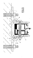
- the combination of the wall plate with an angle plate described in claims 10 and 11 is used to mount post profiles between the ceiling panels of a building, in which the brackets are not mounted next to each other, as in the case of continuous post profiles in the case of curtain walls, but opposite one another.
- This embodiment is therefore suitable for fastening post profiles between ceiling panels on the one hand and as a connection for an otherwise continuous facade in front of the ceiling panels.
- the embodiment of the openings in the leg plates as an elongated hole extending from the mounting end to the free end thereof allows the post profile to be adjusted in the direction of the wall plate or in the opposite direction away from the latter.
- the three-dimensional adjustability of the device is thus given.
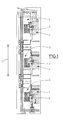
- the facade fastening system shown in Fig. 1 shows three fastening brackets 2 directly connected to the wall 1, in which continuous post profiles 3 are fixed. 2 shows two brackets 2, each of which is mounted via an angle plate 4 between two ceiling plates 5 and connected to a post profile 3.
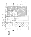
- FIG. 3 and 4 show the detailed structure of the console 2, the drawing plane of FIG. 3 running equally to the longitudinal direction 6 and the drawing plane of FIG. 4 being perpendicular to the drawing plane of FIG. 3 and the same to the transverse direction 7 and the direction of repulsion ( 15) runs.
- the console itself consists essentially of a wall plate 8 and two leg plates 9.
- the wall plate 8 is fastened with two fastening nuts 10 to two anchor pins 11 protruding from the wall 1. These anchor pins 11 pass through the wall plate 8 in two wall plate slots 12, both of which lie on the wall plate transverse axis and are cut by it. If the anchor pins 11 are already inserted, the wall plate 8 can be displaced in the two wall plate elongated holes relative to the wall 1 in the transverse direction 7 running parallel to its wall plate transverse axis. In the final assembly state, the wall plate 8 faces the wall 1 with its wall end face 13 and faces away from its free side 14, the wall end face 13 partially resting firmly against the wall 1.
- the post profile 3 lies perpendicular to the wall, with its longitudinal axis at right angles to the longitudinal direction 6 as well as to the transverse direction 7, extending in its stepping direction 15, between the leg plates 9.
- the leg plate outer sides 16 each have at the assembly ends 17 of the leg plates 9 a C-shaped guide rail 18 with the same cross-section to the transverse direction 7.
- the guide rail 18 has a longitudinal opening 6 on its head side 19, which limits it in the longitudinal direction 6, into which passage opening 20 extends an adjusting thread 21 is formed.
- the receiving groove 24 has a C-shaped cross-section which is the same as the transverse direction 7 and serves as a guide groove for the guide rails 18 located on the leg plates 9, which comprises them in the manner of a claw.
- the leg plates 9 are inserted with their guide rails 18 on a groove collar 25 into the receiving grooves 24 extending in the longitudinal direction 6 over the entire length of the wall plate 26 in the longitudinal direction 6.
- the guide rails 18 sliding in the longitudinal direction 6 in the receiving grooves 24 are secured in the longitudinal direction 6 by an adjusting screw 27 screwed into the adjusting thread 21 formed on the head side 19.
- the adjusting screw head 28 is supported on the groove collar 25 of the receiving groove 24 via a support disk 29 which absorbs the forces acting in the longitudinal direction 6 when the bracket 2 is to act as a fixed bearing in the facade fastening system.
- the outer flank 30 of the projections 22 is preferably designed as an Allen screw, approximately in the direction of the bisector 32 of the transverse direction 7 and the direction of repulsion 15 introduced to the wall 1 securing bolt 31 such that it passes through the outer flanks 30 of the receiving grooves 24 and the guide plates 18 in an alignment line 33 corresponding to its direction.
- the securing bolt 31 is an additional securing of the fixed bearing. If the bracket 2 acts as a floating bearing in the facade fastening system, there is preferably a play of 5 mm between the adjusting screw head 28 and the groove collar 25. The securing bolt 31 is not required for the floating bearing without replacement.
- Fig. 5 shows a special embodiment of the guide rails 18 on the one hand and the corresponding grooves 24 on the other.
- beads 34 pointing in the transverse direction 7 and extending in the longitudinal direction 6 are formed in the receiving grooves 24, which beads are filled with fixing projections 35 protruding from the guide rails 18 in the transverse direction 7 when the guide rails 18 are inserted.
- This combination of the beads 34 and the fixing projections 35 has the effect that the position of the leg plate ends 36 facing away from the mounting ends 17 in the direction of separation 15 cannot be changed in the transverse direction 7.
- This anti-twist device comes into play above all when the brackets 2 are still to be described.
- the post profile 3 is in the direction of repulsion 15 inserted into the free side 14 of the wall plate 8.
- the leg plates 9 are each broken approximately in the middle between the mounting end 17 and the leg plate free end 36 by a leg plate elongated hole 39 which extends in the direction 15 and which is located in the longitudinal direction approximately in the upper third of the leg plate facing the head side 19 of the guide rail 18.
- the post profile 3 is completely penetrated in the transverse direction 7 by a transverse bore 40 into which a transverse sleeve 41 is introduced.
- the post profile 3 is fixed in the hollow cross section 38 in such a way that a retaining screw running in the direction of its central longitudinal axis 50 parallel to the transverse direction 7 42 penetrates the leg plate elongated holes 39 and the transverse sleeve 41 lying in the transverse bore 40 in the transverse direction 7.
- additional holding plates 43 are mounted on the outside of the leg plate.
- the respective active surface 44 of the holding plate 43 facing the respective outer side of the leg plate 16 is profiled like a tooth surface.
- tooth ribs 45 protrude from the outside of the side plates 16 and extend in the longitudinal direction parallel to the wall 1 over the entire outside of the side plates. Tooth troughs 46 run parallel to the tooth ribs 45.
- the tooth surfaces on the outer side of the leg plate 16 and the respective active surfaces 44 of the holding plates 43 facing them are designed as mirror images of one another.
- the tooth surface-like leg plate outer sides 16 and the active surfaces 44 engage in the manner of a meshing pair of gears, with a toothed rib 45 in each case lying in a tooth valley 46 corresponding to it. If the leg plate outer sides 16 and the active surfaces 44 are in such engagement, they can no longer be displaced relative to one another in the direction of repulsion 15.
- the clamping surfaces 47 which run identically to the active surfaces 44, are present on the holding plates 43.
- the holding plates 43 are pierced by a through hole 48 which extends from the clamping surfaces 47 to the active surfaces 44. In the assembled state, the through bore 48 runs parallel to the transverse direction 7.
- the retaining plates 43 are penetrated by the retaining screw 42 in their through bores 48 in the final assembly state such that the through bores 48 of the retaining plates 43, the leg plate elongated holes 39 and the transverse bore 40 of the post profile 3 are aligned with one another in the direction of the central longitudinal axis 50 of the retaining screw 42 running parallel to the transverse direction 7 run.
Landscapes
- Engineering & Computer Science (AREA)
- Architecture (AREA)
- Physics & Mathematics (AREA)
- Electromagnetism (AREA)
- Civil Engineering (AREA)
- Structural Engineering (AREA)
- Load-Bearing And Curtain Walls (AREA)
- Connection Of Plates (AREA)
- Finishing Walls (AREA)
- Mutual Connection Of Rods And Tubes (AREA)
- Joining Of Building Structures In Genera (AREA)
- Clamps And Clips (AREA)
Priority Applications (1)
| Application Number | Priority Date | Filing Date | Title |
|---|---|---|---|
| DE9117097U DE9117097U1 (de) | 1990-03-02 | 1991-02-23 | Befestigungskonsole für ein Fassadenbefestigungssystem |
Applications Claiming Priority (4)
| Application Number | Priority Date | Filing Date | Title |
|---|---|---|---|
| DE4006515 | 1990-03-02 | ||
| DE4006515 | 1990-03-02 | ||
| DE4016164 | 1990-05-19 | ||
| DE4016164A DE4016164A1 (de) | 1990-03-02 | 1990-05-19 | Befestigungskonsole fuer ein fassadenbefestigungssystem |
Publications (3)
| Publication Number | Publication Date |
|---|---|
| EP0444552A2 true EP0444552A2 (fr) | 1991-09-04 |
| EP0444552A3 EP0444552A3 (en) | 1992-03-18 |
| EP0444552B1 EP0444552B1 (fr) | 1995-12-13 |
Family
ID=25890694
Family Applications (1)
| Application Number | Title | Priority Date | Filing Date |
|---|---|---|---|
| EP91102687A Expired - Lifetime EP0444552B1 (fr) | 1990-03-02 | 1991-02-23 | Console de fixation pour système de montage de façade rideau |
Country Status (3)
| Country | Link |
|---|---|
| EP (1) | EP0444552B1 (fr) |
| AT (1) | ATE131562T1 (fr) |
| DE (2) | DE4016164A1 (fr) |
Cited By (7)
| Publication number | Priority date | Publication date | Assignee | Title |
|---|---|---|---|---|
| ES2139489A1 (es) * | 1996-10-14 | 2000-02-01 | Adell Argiles Josep Maria | Anclaje para modulos de fachada. |
| CN102900172A (zh) * | 2011-07-28 | 2013-01-30 | 沈阳远大铝业工程有限公司 | 幕墙用t型连接构件 |
| CN103088943A (zh) * | 2013-01-22 | 2013-05-08 | 沈阳远大铝业工程有限公司 | 幕墙三维调整式转接装置 |
| CN105113683A (zh) * | 2015-09-15 | 2015-12-02 | 山东津单幕墙有限公司 | 一种设有条窗的单元装配式建筑外围护系统及其施工方法 |
| CN111173178A (zh) * | 2020-01-14 | 2020-05-19 | 湖南美美幕墙装饰有限公司 | 一种新型幕墙立柱与建筑主体连接装置及方式 |
| CN113818608A (zh) * | 2021-09-29 | 2021-12-21 | 郭锋 | 一种建筑幕墙防脱落装置 |
| CN115653170A (zh) * | 2022-09-08 | 2023-01-31 | 中亿丰建设集团股份有限公司 | 一种带竖向开放式石材线条单元幕墙系统及其安装工艺 |
Families Citing this family (1)
| Publication number | Priority date | Publication date | Assignee | Title |
|---|---|---|---|---|
| US20150135615A1 (en) | 2013-11-08 | 2015-05-21 | Cupples International Inc. | Perimeter wall |
Family Cites Families (5)
| Publication number | Priority date | Publication date | Assignee | Title |
|---|---|---|---|---|
| FR1278386A (fr) * | 1961-01-18 | 1961-12-08 | Perfectionnements aux châssis de support de panneaux | |
| DE2801621A1 (de) * | 1978-01-14 | 1979-07-19 | Manfred Ing Grad Hoffknecht | Vorrichtung zur zwaengungsfreien befestigung von fassadenbekleidungen an der fassaden-rohbauwand |
| DE3032359C2 (de) * | 1980-08-28 | 1986-06-12 | Hermann 6380 Bad Homburg Loos | Unterkonstruktion zur Befestigung einer Wandbekleidung |
| DE3405254A1 (de) * | 1984-02-15 | 1985-08-22 | Gerhard Dipl.-Ing. 6478 Nidda Schmollack | Vorrichtung zum befestigen von wandbekleidungselementen |
| DE9000835U1 (de) * | 1990-01-26 | 1990-04-05 | Schüco International GmbH & Co, 4800 Bielefeld | Fixier- und Justiervorrichtung für die flächigen Bauelemente einer vertikale Pfosten aufweisenden Vorhängefassade eines Gebäudes |
-
1990
- 1990-05-19 DE DE4016164A patent/DE4016164A1/de not_active Withdrawn
-
1991
- 1991-02-23 DE DE59107050T patent/DE59107050D1/de not_active Expired - Fee Related
- 1991-02-23 EP EP91102687A patent/EP0444552B1/fr not_active Expired - Lifetime
- 1991-02-23 AT AT91102687T patent/ATE131562T1/de not_active IP Right Cessation
Cited By (9)
| Publication number | Priority date | Publication date | Assignee | Title |
|---|---|---|---|---|
| ES2139489A1 (es) * | 1996-10-14 | 2000-02-01 | Adell Argiles Josep Maria | Anclaje para modulos de fachada. |
| CN102900172A (zh) * | 2011-07-28 | 2013-01-30 | 沈阳远大铝业工程有限公司 | 幕墙用t型连接构件 |
| CN102900172B (zh) * | 2011-07-28 | 2015-07-29 | 沈阳远大铝业工程有限公司 | 幕墙用t型连接构件 |
| CN103088943A (zh) * | 2013-01-22 | 2013-05-08 | 沈阳远大铝业工程有限公司 | 幕墙三维调整式转接装置 |
| CN103088943B (zh) * | 2013-01-22 | 2015-05-13 | 沈阳远大铝业工程有限公司 | 幕墙三维调整式转接装置 |
| CN105113683A (zh) * | 2015-09-15 | 2015-12-02 | 山东津单幕墙有限公司 | 一种设有条窗的单元装配式建筑外围护系统及其施工方法 |
| CN111173178A (zh) * | 2020-01-14 | 2020-05-19 | 湖南美美幕墙装饰有限公司 | 一种新型幕墙立柱与建筑主体连接装置及方式 |
| CN113818608A (zh) * | 2021-09-29 | 2021-12-21 | 郭锋 | 一种建筑幕墙防脱落装置 |
| CN115653170A (zh) * | 2022-09-08 | 2023-01-31 | 中亿丰建设集团股份有限公司 | 一种带竖向开放式石材线条单元幕墙系统及其安装工艺 |
Also Published As
| Publication number | Publication date |
|---|---|
| DE59107050D1 (de) | 1996-01-25 |
| EP0444552A3 (en) | 1992-03-18 |
| EP0444552B1 (fr) | 1995-12-13 |
| ATE131562T1 (de) | 1995-12-15 |
| DE4016164A1 (de) | 1991-09-05 |
Similar Documents
| Publication | Publication Date | Title |
|---|---|---|
| EP0945577B2 (fr) | Utilisation d'une barre profilée pour soutenir des encadrements pour portes ou fenêtres | |
| EP0436869A2 (fr) | Liaison au niveau du raccordement entre poteau et traverse d'une structure porteuse pour ou un mur de façade | |
| EP0476289A1 (fr) | Construction de façade comprenant une structure de support à structure profilée fixée à lavant | |
| EP3258022A1 (fr) | Rail d'ancrage et ouvrage comprenant un rail d'ancrage | |
| EP0444552B1 (fr) | Console de fixation pour système de montage de façade rideau | |
| DE202015104250U1 (de) | Pfosten-Riegel-Verbindung | |
| EP0369326A2 (fr) | Dispositif isolant de liaison pour panneaux de construction | |
| EP1840314B1 (fr) | Composant coupe-feu | |
| EP1439278A2 (fr) | Joint, notamment joint de contact ou joint automatiquement abaissable pour portes avec support adjustable | |
| WO2018024448A1 (fr) | Système d'assemblage de châssis | |
| DE19744832C2 (de) | Anordnung für den Einbau eines Fensterrahmens | |
| EP1681398B1 (fr) | Connecteur en T pour ossature faite de montants et traverses perpendiculaires | |
| DE9313426U1 (de) | Lüftungsvorrichtung für Räume | |
| AT524849B1 (de) | Montagesystem für Geländer und Absturzsicherungen | |
| EP0623530A1 (fr) | Système de convoyeur aérien avec un set de profilés de montage | |
| DE202004009649U1 (de) | Verbindungssystem | |
| DE102017120676B4 (de) | Deckenverkleidungssystem | |
| EP0052158A1 (fr) | Bloc-support pour revêtements de façades | |
| EP4575119B1 (fr) | Raccord en t et procédé d'assemblage d'un raccord en t | |
| DE202020000211U1 (de) | Distanzstück und System zum dauerhaften Befestigen eines Bauteils an wenigstens einem Befestigungspunkt | |
| CH656915A5 (de) | Vorrichtung zur kupplung senkrecht zueinander verlaufender treibstangen. | |
| DE9117097U1 (de) | Befestigungskonsole für ein Fassadenbefestigungssystem | |
| EP2213806B1 (fr) | Construction de façades ou de toit vitré | |
| DE202024101757U1 (de) | Tragschiene | |
| DE10044951C1 (de) | Sprossenverbindung für Glasdächer bzw. Glasfassaden |
Legal Events
| Date | Code | Title | Description |
|---|---|---|---|
| PUAI | Public reference made under article 153(3) epc to a published international application that has entered the european phase |
Free format text: ORIGINAL CODE: 0009012 |
|
| AK | Designated contracting states |
Kind code of ref document: A2 Designated state(s): AT CH DE FR LI |
|
| EL | Fr: translation of claims filed | ||
| PUAL | Search report despatched |
Free format text: ORIGINAL CODE: 0009013 |
|
| AK | Designated contracting states |
Kind code of ref document: A3 Designated state(s): AT CH DE FR LI |
|
| 17P | Request for examination filed |
Effective date: 19920406 |
|
| 17Q | First examination report despatched |
Effective date: 19930407 |
|
| GRAA | (expected) grant |
Free format text: ORIGINAL CODE: 0009210 |
|
| AK | Designated contracting states |
Kind code of ref document: B1 Designated state(s): AT CH DE FR LI |
|
| REF | Corresponds to: |
Ref document number: 131562 Country of ref document: AT Date of ref document: 19951215 Kind code of ref document: T |
|
| REF | Corresponds to: |
Ref document number: 59107050 Country of ref document: DE Date of ref document: 19960125 |
|
| REG | Reference to a national code |
Ref country code: CH Ref legal event code: NV Representative=s name: E. BLUM & CO. PATENTANWAELTE |
|
| ET | Fr: translation filed | ||
| PLBE | No opposition filed within time limit |
Free format text: ORIGINAL CODE: 0009261 |
|
| STAA | Information on the status of an ep patent application or granted ep patent |
Free format text: STATUS: NO OPPOSITION FILED WITHIN TIME LIMIT |
|
| 26N | No opposition filed | ||
| REG | Reference to a national code |
Ref country code: CH Ref legal event code: PUE Owner name: EDUARD HUECK GMBH & CO. KG Free format text: W. HARTMANN & CO (GMBH & CO)#ROEDINGSMARKT 39#D-20459 HAMBURG (DE) -TRANSFER TO- EDUARD HUECK GMBH & CO. KG#LOHER STRASSE 9#58511 LUEDENSCHEID (DE) |
|
| REG | Reference to a national code |
Ref country code: FR Ref legal event code: TP |
|
| PGFP | Annual fee paid to national office [announced via postgrant information from national office to epo] |
Ref country code: FR Payment date: 20060215 Year of fee payment: 16 |
|
| PGFP | Annual fee paid to national office [announced via postgrant information from national office to epo] |
Ref country code: AT Payment date: 20060220 Year of fee payment: 16 |
|
| PGFP | Annual fee paid to national office [announced via postgrant information from national office to epo] |
Ref country code: CH Payment date: 20060221 Year of fee payment: 16 |
|
| PGFP | Annual fee paid to national office [announced via postgrant information from national office to epo] |
Ref country code: DE Payment date: 20060428 Year of fee payment: 16 |
|
| PG25 | Lapsed in a contracting state [announced via postgrant information from national office to epo] |
Ref country code: LI Free format text: LAPSE BECAUSE OF NON-PAYMENT OF DUE FEES Effective date: 20070228 Ref country code: CH Free format text: LAPSE BECAUSE OF NON-PAYMENT OF DUE FEES Effective date: 20070228 |
|
| REG | Reference to a national code |
Ref country code: CH Ref legal event code: PL |
|
| PG25 | Lapsed in a contracting state [announced via postgrant information from national office to epo] |
Ref country code: AT Free format text: LAPSE BECAUSE OF NON-PAYMENT OF DUE FEES Effective date: 20070223 |
|
| REG | Reference to a national code |
Ref country code: FR Ref legal event code: ST Effective date: 20071030 |
|
| PG25 | Lapsed in a contracting state [announced via postgrant information from national office to epo] |
Ref country code: DE Free format text: LAPSE BECAUSE OF NON-PAYMENT OF DUE FEES Effective date: 20070901 |
|
| PG25 | Lapsed in a contracting state [announced via postgrant information from national office to epo] |
Ref country code: FR Free format text: LAPSE BECAUSE OF NON-PAYMENT OF DUE FEES Effective date: 20070228 |