EP0444666A2 - Interconnexion pour système d'alimentation électrique - Google Patents
Interconnexion pour système d'alimentation électrique Download PDFInfo
- Publication number
- EP0444666A2 EP0444666A2 EP91103008A EP91103008A EP0444666A2 EP 0444666 A2 EP0444666 A2 EP 0444666A2 EP 91103008 A EP91103008 A EP 91103008A EP 91103008 A EP91103008 A EP 91103008A EP 0444666 A2 EP0444666 A2 EP 0444666A2
- Authority
- EP
- European Patent Office
- Prior art keywords
- frequency
- power
- signal
- output
- inverter
- Prior art date
- Legal status (The legal status is an assumption and is not a legal conclusion. Google has not performed a legal analysis and makes no representation as to the accuracy of the status listed.)
- Granted
Links
Images


Classifications
-
- H—ELECTRICITY
- H02—GENERATION; CONVERSION OR DISTRIBUTION OF ELECTRIC POWER
- H02J—ELECTRIC POWER NETWORKS; CIRCUIT ARRANGEMENTS OR SYSTEMS FOR SUPPLYING OR DISTRIBUTING ELECTRIC POWER; SYSTEMS FOR STORING ELECTRIC ENERGY
- H02J3/00—Circuit arrangements for AC mains or AC distribution networks
- H02J3/38—Arrangements for feeding a single network from two or more generators or sources in parallel; Arrangements for feeding already energised networks from additional generators or sources in parallel
- H02J3/388—Arrangements for the handling of islanding, e.g. for disconnection or for avoiding the disconnection of power
Definitions
- the present invention relates to a system of interconnection for supplying electric power to load by connecting an inverter for converting DC power to AC power and an electric power system to the load.
- the present invention relates to the interconnection system which has switching means for disconnecting the interconnection when necessary.
- FIG.8 shows general conventional power interconnection system shown, for instance, in the Japanese published unexamined patent application Sho 62-114435 as the prior art thereto.
- an electric power system 7 comprises at least one generator 1, a transmission line 2 connected to the generator 1, a trunk distribution line 3 connected through a trunk line switch 4 to the transmission line 2, and branch line switches 6, 6, ⁇ ⁇ ⁇ ⁇ connecting the trunk distribution line 3 to the branch lines 5, i.e. feeders.
- Loads 8, 8, ⁇ ⁇ ⁇ ⁇ ⁇ are connected to the branch lines 5, and each or at lease one branch line 5 is connected through a system interconnection switch 11 to a power converter 10, which is connected to a DC power output apparatus 9 for generating DC or storing power in DC.
- the electric power from the DC power output apparatus 9 is converted by the power converter 10 and fed through the system interconnection switch 11 to the loads 8, 8, ⁇ ⁇ ⁇ ⁇ ⁇ ⁇ .
- the interconnection system is disconnected by opening either of the trunk line switch 4 or the branch line switch 6 thereby to make the loads 8, 8, ⁇ ⁇ ⁇ ⁇ ⁇ power-off state.
- Distributed power sources which are to be interconnected by the power converter 10 are generally provided in the lower parts (i.e. in the part of loads) of the power system because of its sizes.
- the interconnected system may have such a dangerous state of islanding operation, that is inverse application of voltage from the power converter 10 when the switches 4 and 6 in the power system are opened. Therefore, accompanying to the opening of either of the switch 4 or switch 8 in the power system 7, the system interconnection switch 11 must be immediately opened, thereby to disconnect the interconnection.
- the system interconnection switch 11 is operated by auxiliary contacts of the switches 4 and 6.
- such system has an impractical problem that the wiring length is very long because the switches are located at very distant places.
- FIG.7 which is the circuit of the invention disclosed and claimed in the above-mentioned Japanese unexamined published patent application Sho 62-114435, proposes a configuration that the state of no application of voltage from the electric power system 7 after opening of a switch 6 therein is detected by a power converter 10 itself, thereby to open an interconnection switch 11.
- FIG.7 The configuration of the prior art circuit of FIG.7 is elucidated hereafter.
- the same numerals as those used in FIG.6 show corresponding parts and components.
- the power converter 10 comprises an inverter 12 and an interconnection reactor 13 which is a winding of transformer including a reactance therein. Both ends of the reactor 13 are connected to a phase difference detector 14. And the phase difference of currents at both ends of the interconnection reactor 13 is detected from both ends as a phase difference between a first voltage signal S1 and a second voltage signal S2 both inputted to the phase difference detector 14. Output signal S3 from the phase difference detector 14 is given to a first adder 98, whereto phase reference signal S0 from a phase reference signal generator 15 is also added in opposite polarity. The output from the adder 98 is given to a phase controller 16 which contains an amplifier.
- Output signal S4 of the phase controller 16 is given to a second adder 99, whereto an output S5 from a periodical disturbance generator 20 is given.
- Output S6 from the second adder 99 is given to an inverter controller 17, whose output is given to the inverter 12 thereby to control frequency of the output power of the inverter 12.
- FIG.8 is a circuit diagram of a case that plural number of power output apparatuses 9, 9, ⁇ ⁇ ⁇ are connected through respective power converters 10, 10, ⁇ ⁇ ⁇ .
- the disturbances of respective converters may offset i.e., cancel each other when their timings of periodical shift would opposite each other.
- the abnormality of frequency does not appear or belatedly appear.
- the frequency abnormality may appear very strongly when their timings of periodical shift would agree each other.
- FIG.9 shows a prior art example wherein a co-generator 21, such as a diesel engine generator, is connected parallely the loads 8, 8, ⁇ ⁇ ⁇ .
- a co-generator 21 such as a diesel engine generator
- the present invention purposes to dissolve the above-mentioned problems of difficulties in disconnection of the interconnection system, and to provide an improved interconnection system capable of reliably disconnecting of the power converter from the electric power system.
- the interconnection system for electric power system for interconnection between an electric power system and power converter comprises: a frequency deviation detector for detecting frequency deviation of the converted AC power outputted from the inverter and issuing a first signal, a band-pass filter for passing a selected frequency band component from the first signal, an inert zone circuit for passing output signal from the band-pass filter only for the component having levels above a predetermined threshold level, thereby outputting a third signal, a control circuit for positively feeding back the third output signal and the output of the disturbance generator, thereby to increase frequency deviation of the converted AC power from the inverter, and an output abnormality detector for making a disconnection of the inverter from the interconnection with the electric power system, when frequency deviation of the inverter exceeds a predetermined reference value of frequency deviation, or when deviation of intensity of output current or output power of the inverter exceeds a predetermined reference level of deviation.
- frequency of current to the load is fixed to that of the electric power system when the converter is interconnected to the electric power system, whereas when the interconnection is disconnected and the frequency variation becomes above the predetermined reference value of deviation the frequency variation is positively fed back thereby to increase frequency variation of the current to the load. And the positive-fed back increased frequency variation is detected, and thereby the interconnection of the power converter to the electric power system is disconnected certainly, Therefore undesirable inverse feeding of electric power is prevented.
- the loop gain of the phase controlling loop (24, 99, 16, 17, 12, 13) is made higher than 1. Therefore, the positive-fed back is stably obtained even when the plural power converters and/or co-generator are connected to the electric power system and the load. And satisfactory operation is obtainable such that, in the operation in the interconnected state the enough controllability is obtainable, whereas in the operation in the disconnected state the sufficient variation of frequency or road current is obtainable. Therefore, disconnection of the interconnecting switch can be made reliably, thereby preventing dangerous inverse feeding of power.
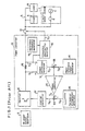
- FIG.1 is a circuit block diagram of a first embodiment.
- an electric power system 7 and a power converter 10, which converts DC power output of a DC power output apparatus 9 into an AC power are interconnected by an interconnection switch 11; and a load 8 and a co-generator 21, which is for instance a diesel engine generator, are interconnected with the above-mentioned interconnection system.
- the electric power system 7 comprises at least one generator 1 such as a power plant and a branch line switch 6.
- the electric power system 7, the load 8 and the co-generator 21, are connected through the interconnection switch 11 to the power converter 10.
- the power converter 10 comprises an inverter 12, which is for converting DC power from the DC power output apparatus 9 into AC power, and an interconnection reactor 13, wherethrough the inverted output power is outputted. Both ends of the interconnection reactor 13 are connected to input terminals of a phase difference detector 14, so that a first voltage signal S1 and a second, voltage signal S2 From the above-mentioned both ends are given to the phase difference detector 14.
- the phase difference detector 14 outputs a phase difference signal S3 to an adder 99.
- the Second voltage signal S2 is further given to a frequency deviation detector 22.
- the frequency deviation detector 22 detects deviation ⁇ f of frequency of the voltage, at the interconnection switch 11, of the interconnected system, which comprises the electric power system 7, the co-generator 21 and the power converter 10.
- the frequency deviation ⁇ f is defined by a frequency difference with a reference frequency, such as accurate 60 Hz.
- the output signal S8 of the frequency deviation detector 22 is a voltage which is proportional to the frequency deviation ⁇ f.
- the voltage of the output signal S8 of the frequency deviation detector 22 usually fluctuates making fluctuation of frequencies mainly of 2 --- 3 Hz when the co-generator 21 is interconnected.
- the output signal S8 is given through a band-pass filter 23 to an inert zone circuit 24. Then, output of the inert zone circuit 24 is amplified by an amplifier 25 and the amplified signal S9 is given to the adder 99.
- a phase reference signal generator 15 gives a difference signal to the adder 99.
- the adder 99 gives its summed output signal to a phase controller 16.
- An output signal S6 of the phase controller 16 is given to an inverter controller 17 which gives a control signal to the inverter 12 so as to control output power of the inverter 12.
- the first voltage signal S1 is given to a frequency abnormality detector 18 and output of a reference frequency generator 19 is further given to the frequency abnormality detector 18.
- the frequency abnormality detector 18 outputs a frequency abnormality detection signal S7 which drives the interconnection switch 11 to be disconnected.
- the band-pass filter 23, the inert zone circuit 24, the amplifier 25 and the adder 99 is provided featuring the present invention, and it functions to make a positive feed-back under a special condition defined by the band-pass filter 23 and the inert zone circuit 24.
- the band-pass filter 23 is designed in a manner to pass only AC components in a narrow frequency band, for instance 2 --- 3 Hz induced mainly by the interconnection of the co-generator 21.
- the inert zone circuit 24 functions to omit or cut out signal components within a predetermined level. Therefore, the component of the output signal S8 reaches to the amplifier 25 only when the frequency fluctuation is under 3 Hz and that the fluctuation level is above the predetermined level.
- FIG.1 Operation of the embodiment FIG.1 is elucidated.
- the power converter 10 Since the branch line switch 6 and the interconnection switch 11 are closed, the power converter 10 is interconnected to the electric power system 7 and the co-generator 21. Therefore, electric power is supplied to the load 8 from the electric power system 7, from the co-generator 21 and from the power converter 10.
- Frequency deviation of the AC voltage of the interconnected system is detected by the frequency deviation detector 22.
- the frequency of AC voltage is fixed to the frequency of the electric power system 7, end hence the deviation of the frequency detected by the frequency deviation detector 22 is small.
- the output Signal of the frequency deviation detector 22 is given to the band-pass filter 23, and only the component of the frequency which is within the predetermined narrow band (e.g.
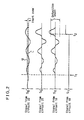
- the inert zone circuit 24 has such inert zone as shown in the wave-form S8 of FIG. 2, wherein two horizontal lines U and L show upper and lower threshold levels of the inert zone.
- the input signal S8 to the inert zone circuit 24 exceeds (goes outside of) the inert zone defined by the threshold levels U and L, the components which exceed the threshold level U and L only are output from the inert zone circuit 24 and amplified by the amplifier 25, to produce the signal S9 of FIG.2. That is, the small amplitude components of the input signal S8 are stopped by the inert zone circuit 24 and is not led to the amplifier 25.
- the output signal S9 from the amplifier 25 is then summed at the adder 99 with the output signal S3 and the output signal from the phase reference signal generator 15, thereby to produce a signal S6 summed and given to the phase controller 16.
- the output signal S6 from the phase controller 16 shown in the time chart S6 of FIG.2 is given to the inverter controller 17, which makes the inverter 12 change the frequency of converted AC current responding to the levels of signal S6. Since the band-pass filter 23 and the inert zone circuit 24 are provided in the control loop to the inverter controller 17, an ordinary very small frequency fluctuation e.g. under 2 --- 3 Hz inherent to the electric power system 7 does not make any output from the amplifier, and hence the phase controller 16 causes no frequency change of output to the inverter controller 17.
- the ordinary small frequency fluctuation (e.g. under 2 --- 3 Hz) in the electric power system 7 does not make any frequency change of the output AC current of the inverter 12. That is, the phase, hence the output AC power of the inverter 12 is controlled stable to a value corresponding to setting of the reference value of the phase difference which is set in the phase reference signal generator 15.
- the generator 1 has its inherent frequency fluctuation characteristic, in case of generator 1 of a large capacity in the utility electric power system, the absolute value of the frequency change is very small and is negligible.
- the co-generator 21 which is for supplying a portion of power for an electric power consumer, the capacity is relatively small.
- the co-generator 21 generally has an inherent frequency fluctuation range, which is several times larger than that of the generator 1 of the utility electric power system 7, and it is for instance from 2 to 3 Hz. Therefore, when the branch line switch 6 is opened at the time of t1 of FIG.2, the frequency fluctuation which is inherent in the co-generator 21 appears. And hence, level fluctuation with a small frequency of several Hz (e.g.
- the process that the positive feed-back is made is as follows. Since the output signal S6 of FIG.2 which is output from the phase controller 16 causes to control frequency of the inverter 12 through the function of the inverter controller 17, the frequency of the output voltage of the inverter 12 varies responding to inherent fluctuation of frequency of the co-generator, thereby increasing frequency fluctuation at the output end point of the power converter 10. The above-mentioned increased frequency fluctuation further causes the output signal S9 ' of the amplifier to have still increased fluctuation, and increase the frequency fluctuation further, making the positive feedback.
- the frequency fluctuation increases through the positive feed-back function of the loop circuit, which comprises the frequency deviation detector 22, the band-pass filter 23, the inert zone circuit 24, the amplifier 25, the adder 99, the phase controller 16, the inverter controller 17, the inverter 12 and the interconnection reactor 13.
- the frequency abnormality detector 18, which compares frequency at the first voltage signal S1 and a reference frequency from the reference frequency generator 19, outputs a frequency abnormality signal S7 to the interconnection switch 11 at the time t2, as shown by the signal S7 in FIG. 2. That is, at the time t2, the level of output signal S6 of the output of the phase controller 16 exceeds a predetermined abnormality detection level, which is correspondingly shown in the signal S6 of FIG.2.
- the influence of the frequency fluctuation of the output AC current of the inverter 12 to the frequency of the load 8 depends on the values of the interconnection reactor 13 and reactance of the co-generator 21.
- the influence to the load 8 is not so great because the reactance of the interconnection reactor 13 in the converter 10 is relatively large.
- the gains of the amplifier 25 and the phase controller 16 in a manner to make the loop gain for the frequency fluctuation larger than 1, the positive feed-back in the loop is obtainable.
- the co-generator 21 of a large capacity it is general that the interconnection system is configured to be disconnected by signal transmission.
- the load is supplied with the power from other sub-power system in order to compensate the shortage of power from its co-generator.
- the present invention system operates reliably as follows: when the respective power converters as distributed power sources are disconnected, the co-generator easily becomes to overload state, and hence the disconnection of the interconnection is made easily and certainly.
- the phase reference signal generator 15 comprises an output power detector 15A for detecting output power of the inverter 12, a reference output power generator 15B and a power control circuit 15C, which compares outputs of the output power detector 15A and the reference output power generator 15B and outputs a phase reference signal to the adder 99.
- the power control circuit 15C outputs the phase reference signal in a manner to control the inverter controller 17 such that output power of the inverter 12 becomes a predetermined set value.
- the phase reference signal generator 15 functions to issue its output to make the phase instruction signal S6 be controlled so as to adjust the power to be supplied from the power converter 10 to the load 8 becomes a predetermined power amount.
- the present invention is applicable to any types of system wherein output power of the power converter 10 is controlled by controlling the phase of the output voltage (which is equivalent to the frequency controlling).
- the present invention is applicable to still other modified case wherein a large size rotary machine(s) are connected in place of the co-generator(s).
- FIG.3 is a circuit block diagram of another embodiment. Corresponding parts and components to the first embodiment are shown by the same numerals and marks, and the description thereon made in the first embodiment similarly apply. Differences and features of this first embodiment from the first embodiment are as follows.
- a periodical disturbance generator 26 is provided to give its output disturbance signal S10 of FIG.4 to a second adder 100, which is provided between the output end of the amplifier 25 and the first adder 99.
- a periodical disturbance of a specific very low frequency output signal S10 which is e.g.
- the frequency of the output current of the inverter 12 is varied responding to the periodical disturbance of the signal S10 ⁇ That is, the frequency of the output power varies responding to the periodical disturbance. Therefore, of course the output power of the inverter 12 varies responding to this periodical frequency variation.
- the variation of the output power does not make substantial influence to the ordinary interconnection operation, when output level of the periodical disturbance generator 26 is selected to such a level that the percentage of the variation amount of the output power of the inverter 12 to the installed capacity should be about several %.
- the frequency of the output power of the inverter makes small fluctuation, there is no substantial influence to the frequency of the electric power system 7, since the latter frequency is fixed to the frequency of the large generators of the electric power system 7.
- the above-mentioned configuration of the example of FIG.3 is effective for both cases having co-generator(s) 21 and excluding co-generator(s) 21.
- the system has the co-generator, its own output frequency functions to trigger an increasing of frequency variation in the interconnection system. That is, when the cycle of the low frequency output signal S10 from the periodical disturbance generator 26 is selected to agree with the cycle of inherent frequency variation of the co-generator, the variation of frequency is increased.
- Waveform of output signal S10 of the periodical disturbance generator 26 may be triangular wave, besides the sinusoidal wave shown in FIG.4.
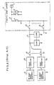
- FIG.5 is a block diagram of a still other embodiment of the invention.
- a detection means for the system disconnection means to detect intensity of the AC output current of a specific frequency band is adopted, in place of the means for detection of the frequency abnormality as in the above-mentioned examples of FIG.1 and FIG.3. That is, the disconnection switch 11 is to be disconnected when the current intensity of the power converter 10 becomes outside a predetermined level, and the interconnection is disconnected.
- the circuit of FIG.5 has a current detector 27 which detects intensity of output current of the power converter 10 and gives its output to a second band-pass filter 28, which has a narrow pass-band such as 3 ⁇ 60 Hz. Then output of the band-pass filter 28 is compared with a reference value of the AC current given from a reference AC current generator 29 at a current abnormality detector 30. And the output signal S7 ' of the current abnormality detector 30 is given to the interconnection disconnector switch 11, to make the disconnection of the switch 11.
- the frequency of the output current of the inverter 12 is varied responding to frequency of some frequency determining means (for instance, the co-generator 21 in case of the circuit of FIG.1, or the periodic frequency disturbance generator 26 in case of the circuit of FIG.3). And the frequency variation is gradually increased by the positive feed-back, as described with reference to FIG.1 and FIG.3.
- the variation of the frequency of the output current of the inverter 12 induces corresponding variation of the output current of the inverter 12.
- fluctuation component of a particular frequency is detected, and intends to detect the component at the time when its level is above a predetermined level.
- the AC output current is detected by the current detector 27, and led to the second band-pass filter 28, which detects the current of the same frequency component as that of the frequency fluctuation. Output of the second band-pass filter 28 is then compared with output of the reference AC current generator 29. When output of the second band-pass filter 28 exceeds the output level get by the reference AC current generator 29, the current abnormality detector 30 generated an output, which drives the interconnection switch 11 to be disconnected.
- This embodiment of the type which detects the current abnormality has higher reliability of detection and more simple circuit configuration than the embodiments of detecting the frequency deviations, since the deviation of the current intensity makes sufficiently large output in comparison with the deviation of the frequency. Therefore the current-intensity deviation-detection is applicable in place of the frequency abnormality detection circuit in the aforementioned embodiments of FIG.1 and FIG.3.
Landscapes
- Engineering & Computer Science (AREA)
- Power Engineering (AREA)
- Supply And Distribution Of Alternating Current (AREA)
- Inverter Devices (AREA)
Applications Claiming Priority (2)
| Application Number | Priority Date | Filing Date | Title |
|---|---|---|---|
| JP52099/90 | 1990-03-02 | ||
| JP2052099A JPH03256533A (ja) | 1990-03-02 | 1990-03-02 | 系統連系システム |
Publications (3)
| Publication Number | Publication Date |
|---|---|
| EP0444666A2 true EP0444666A2 (fr) | 1991-09-04 |
| EP0444666A3 EP0444666A3 (en) | 1992-10-14 |
| EP0444666B1 EP0444666B1 (fr) | 1995-12-06 |
Family
ID=12905399
Family Applications (1)
| Application Number | Title | Priority Date | Filing Date |
|---|---|---|---|
| EP91103008A Expired - Lifetime EP0444666B1 (fr) | 1990-03-02 | 1991-02-28 | Interconnexion pour système d'alimentation électrique |
Country Status (5)
| Country | Link |
|---|---|
| US (1) | US5111377A (fr) |
| EP (1) | EP0444666B1 (fr) |
| JP (1) | JPH03256533A (fr) |
| CN (1) | CN1018496B (fr) |
| DE (1) | DE69115081T2 (fr) |
Cited By (7)
| Publication number | Priority date | Publication date | Assignee | Title |
|---|---|---|---|---|
| AU655889B2 (en) * | 1992-06-24 | 1995-01-12 | Kabushiki Kaisha Toshiba | Inverter protection device |
| EP0607011A3 (en) * | 1993-01-12 | 1995-09-20 | Toshiba Kk | Control device for system interconnection inverter. |
| EP0810713A3 (fr) * | 1996-05-29 | 1999-01-07 | Sharp Kabushiki Kaisha | Procédé et dispositif pour la détection de l'opération d'islanding dans un onduleur |
| DE102011113846A1 (de) * | 2011-09-21 | 2013-03-21 | Technische Universität Clausthal | Verfahren und Einrichtung zur Detekion eines Inselbetriebs von Energieerzeugungsanlagen |
| EP1808947A3 (fr) * | 2006-01-13 | 2013-09-18 | Omron Corporation | Procédé de détection de fonctionnement isolé, appareil de contrôle de détection d'un fonctionnement isolé d'une alimentation électrique distribuée, appareil de détection de fonctionnement isolé, et alimentation électrique distribuée |
| US9619916B2 (en) | 2011-05-20 | 2017-04-11 | Dream Chip Technologies Gmbh | Method for transmitting digital scene description data and transmitter and receiver scene processing device |
| WO2018197468A1 (fr) * | 2017-04-24 | 2018-11-01 | Wobben Properties Gmbh | Procédé de détection d'une construction de réseau en îlot |
Families Citing this family (34)
| Publication number | Priority date | Publication date | Assignee | Title |
|---|---|---|---|---|
| CA2066490C (fr) * | 1991-04-22 | 1997-10-14 | Nobuo Sashida | Systeme parallele d'inverseurs de sortie a courant alternatif |
| IT1255289B (it) * | 1992-05-26 | 1995-10-26 | Ansaldo Spa | Metodo e circuito per il comando della commutazione di un invertitore in "sliding-mode" e in pwm con tensione di uscita a tre livelli |
| IT1255581B (it) * | 1992-07-22 | 1995-11-09 | Ansaldo Spa | Dispositivo circuitale per evitare la saturazione del trasformatore in un convertitore cc/ca con invertitore regolatore in retroazione |
| WO1994003957A1 (fr) * | 1992-08-07 | 1994-02-17 | Kabushiki Kaisha Shikoku Sogo Kenkyujo | Dispositif permettant d'eviter la charge a l'envers |
| JP3029185B2 (ja) * | 1994-04-12 | 2000-04-04 | キヤノン株式会社 | 単独運転防止装置、それを用いた分散型発電装置及び発電システム |
| JP2949202B2 (ja) * | 1995-03-22 | 1999-09-13 | 西芝電機株式会社 | 系統連系保護装置 |
| JP2767214B2 (ja) * | 1995-03-28 | 1998-06-18 | 西芝電機株式会社 | 系統連系保護装置 |
| EP0740387B1 (fr) * | 1995-04-21 | 2002-06-12 | General Electric Company | Système d'interconnexion pour la transmission de puissance entre systèmes électriques |
| US5742515A (en) * | 1995-04-21 | 1998-04-21 | General Electric Co. | Asynchronous conversion method and apparatus for use with variable speed turbine hydroelectric generation |
| US5952816A (en) * | 1995-04-21 | 1999-09-14 | General Electric Co. | Compensation for power transfer systems using variable rotary transformer |
| US5841267A (en) * | 1995-04-21 | 1998-11-24 | General Electric Co. | Power flow control with rotary transformers |
| US5953225A (en) * | 1995-04-21 | 1999-09-14 | General Electric Co. | Power flow control and power recovery with rotary transformers |
| DE69623692T2 (de) * | 1995-05-31 | 2003-05-22 | Kabushiki Kaisha Meidensha, Tokio/Tokyo | Verfahren und Vorrichtung zum Detektieren des Islanding-Betriebes eines verteilten Generators |
| EP0800717A4 (fr) * | 1995-10-31 | 2007-01-03 | Gen Electric | Systeme d'interconnexion pour la transmission de puissance entre des systemes electriques |
| JP4076721B2 (ja) * | 1997-11-24 | 2008-04-16 | エイチ. ウィルス、ロバート | 分散型発電用耐単独運転方法および装置 |
| JP3547355B2 (ja) * | 1999-12-28 | 2004-07-28 | 株式会社日立製作所 | 電力変換システム |
| US6456021B1 (en) | 2000-06-30 | 2002-09-24 | General Electric Company | Rotating variable frequency transformer with high voltage cables |
| CA2351895C (fr) | 2000-06-30 | 2009-12-15 | General Electric Company | Ensemble de fixation de bague collectrice pour barre haute puissance de frottement de courant triphase |
| US6465926B2 (en) | 2000-06-30 | 2002-10-15 | General Electric Company | Cleaning/cooling of high-power rotary current collector system |
| US6469414B2 (en) | 2000-06-30 | 2002-10-22 | General Electric Company | Slip-ring mounting assembly for high-power rotary current collector system |
| GB0102212D0 (en) * | 2001-01-29 | 2001-03-14 | Lattice Intellectual Property | Controller |
| JP4118531B2 (ja) * | 2001-05-10 | 2008-07-16 | 株式会社東芝 | 電力調整装置 |
| US7106564B2 (en) * | 2002-01-16 | 2006-09-12 | Ballard Power Systems Corporation | Devices and methods for detecting islanding operation of a static power source |
| WO2003106828A2 (fr) | 2002-06-18 | 2003-12-24 | Ingersoll-Rand Energy Systems Corporation | Systeme de moteur a microturbine |
| US7015597B2 (en) * | 2003-09-11 | 2006-03-21 | Square D Company | Power regulator for power inverter |
| US7016793B2 (en) * | 2003-10-01 | 2006-03-21 | General Electric Company | Method and apparatus for anti-islanding protection of distributed generations |
| US7161257B2 (en) * | 2004-03-08 | 2007-01-09 | Ingersoll-Rand Energy Systems, Inc. | Active anti-islanding system and method |
| TWI278635B (en) * | 2004-12-31 | 2007-04-11 | Ind Tech Res Inst | Method for surely detecting islanding operation |
| JP4664113B2 (ja) * | 2005-04-12 | 2011-04-06 | 国立大学法人京都大学 | 電力系統の固有周波数の監視システム及び監視方法 |
| FI120811B (fi) * | 2008-01-09 | 2010-03-15 | Waertsilae Finland Oy | Sähkövoimansyöttölaitteisto laivakäyttöön |
| JP5505145B2 (ja) * | 2010-07-09 | 2014-05-28 | 富士電機株式会社 | 単独運転検出装置 |
| US9634673B2 (en) * | 2013-01-30 | 2017-04-25 | Virginia Tech Intellectual Properties, Inc. | Anti-islanding detection for three-phase distributed generation |
| JP6299779B2 (ja) * | 2016-02-02 | 2018-03-28 | トヨタ自動車株式会社 | 送電装置及び電力伝送システム |
| CN109980676B (zh) * | 2017-12-28 | 2021-06-25 | 北京天诚同创电气有限公司 | 微电网控制系统及微电网 |
Family Cites Families (9)
| Publication number | Priority date | Publication date | Assignee | Title |
|---|---|---|---|---|
| US3659060A (en) * | 1970-04-08 | 1972-04-25 | Allan L Wolff | System for measuring frequency deviation |
| JPS54103658A (en) * | 1978-02-01 | 1979-08-15 | Hitachi Ltd | Protective circuit |
| GB8412856D0 (en) * | 1984-05-19 | 1984-06-27 | Northern Eng Ind | Frequency detection |
| JPS6192130A (ja) * | 1984-10-11 | 1986-05-10 | 関西電力株式会社 | 電源装置 |
| JPS62114435A (ja) * | 1985-11-12 | 1987-05-26 | 三菱電機株式会社 | 系統連係用電力変換装置 |
| US4820891A (en) * | 1986-11-29 | 1989-04-11 | Kabushiki Kaisha Toshiba | Induction heated cooking apparatus |
| JPH0779551B2 (ja) * | 1987-03-20 | 1995-08-23 | 株式会社日立製作所 | インバ−タ制御装置 |
| JPH0191671A (ja) * | 1987-09-30 | 1989-04-11 | Toshiba Corp | 系統連系用インバータ装置 |
| JP2703239B2 (ja) * | 1987-11-19 | 1998-01-26 | 株式会社東芝 | 系統連系用電力変換装置 |
-
1990
- 1990-03-02 JP JP2052099A patent/JPH03256533A/ja active Pending
-
1991
- 1991-02-28 EP EP91103008A patent/EP0444666B1/fr not_active Expired - Lifetime
- 1991-02-28 DE DE69115081T patent/DE69115081T2/de not_active Expired - Fee Related
- 1991-03-01 US US07/663,168 patent/US5111377A/en not_active Expired - Fee Related
- 1991-03-02 CN CN91101286A patent/CN1018496B/zh not_active Expired
Cited By (13)
| Publication number | Priority date | Publication date | Assignee | Title |
|---|---|---|---|---|
| AU655889B2 (en) * | 1992-06-24 | 1995-01-12 | Kabushiki Kaisha Toshiba | Inverter protection device |
| EP0607011A3 (en) * | 1993-01-12 | 1995-09-20 | Toshiba Kk | Control device for system interconnection inverter. |
| US5537307A (en) * | 1993-01-12 | 1996-07-16 | Kabushiki Kaisha Toshiba | Control device for system interconnection inverter |
| EP0810713A3 (fr) * | 1996-05-29 | 1999-01-07 | Sharp Kabushiki Kaisha | Procédé et dispositif pour la détection de l'opération d'islanding dans un onduleur |
| US6172889B1 (en) | 1996-05-29 | 2001-01-09 | Sharp Kabushiki Kaisha | Inverter apparatus islanding operation detecting method and inverter apparatus capable of surely detecting an islanding operation with a simple construction |
| EP1808947A3 (fr) * | 2006-01-13 | 2013-09-18 | Omron Corporation | Procédé de détection de fonctionnement isolé, appareil de contrôle de détection d'un fonctionnement isolé d'une alimentation électrique distribuée, appareil de détection de fonctionnement isolé, et alimentation électrique distribuée |
| US9619916B2 (en) | 2011-05-20 | 2017-04-11 | Dream Chip Technologies Gmbh | Method for transmitting digital scene description data and transmitter and receiver scene processing device |
| DE102011113846A8 (de) * | 2011-09-21 | 2013-06-20 | Technische Universität Clausthal | Verfahren und Einrichtung zur Detekion eines Inselbetriebs von Energieerzeugungsanlagen |
| WO2013041484A3 (fr) * | 2011-09-21 | 2013-06-20 | Technische Universität Clausthal | Procédé et dispositif de détection d'un fonctionnement en îlot d'installations de production d'énergie |
| DE102011113846B4 (de) * | 2011-09-21 | 2013-07-25 | Technische Universität Clausthal | Verfahren und Einrichtung zur Detekion eines Inselbetriebs von Energieerzeugungsanlagen |
| DE102011113846A1 (de) * | 2011-09-21 | 2013-03-21 | Technische Universität Clausthal | Verfahren und Einrichtung zur Detekion eines Inselbetriebs von Energieerzeugungsanlagen |
| WO2018197468A1 (fr) * | 2017-04-24 | 2018-11-01 | Wobben Properties Gmbh | Procédé de détection d'une construction de réseau en îlot |
| US11081886B2 (en) | 2017-04-24 | 2021-08-03 | Wobben Properties Gmbh | Method for detecting formation of a separate system |
Also Published As
| Publication number | Publication date |
|---|---|
| US5111377A (en) | 1992-05-05 |
| EP0444666B1 (fr) | 1995-12-06 |
| DE69115081T2 (de) | 1996-09-05 |
| EP0444666A3 (en) | 1992-10-14 |
| DE69115081D1 (de) | 1996-01-18 |
| CN1018496B (zh) | 1992-09-30 |
| JPH03256533A (ja) | 1991-11-15 |
| CN1054858A (zh) | 1991-09-25 |
Similar Documents
| Publication | Publication Date | Title |
|---|---|---|
| EP0444666B1 (fr) | Interconnexion pour système d'alimentation électrique | |
| US5329222A (en) | Apparatus and method for dynamic voltage restoration of utility distribution networks | |
| KR890004588B1 (ko) | 전원시스템 및 그의 제어방법 | |
| US6154379A (en) | Electric power conversion device | |
| US5473528A (en) | Parallel connection of different types of AC power supplies of differing capacities | |
| EP0239278B1 (fr) | Appareil capacitif pour la compensation de puissance réactive | |
| US9467070B2 (en) | Decentralized power generation plant having a device and method for detecting an island network | |
| US5162964A (en) | Connection control device for controlling the connection of small generator unit to electric power system | |
| US12107414B2 (en) | Systems and methods for operating an islanded distribution substation using inverter power generation | |
| JP3011605B2 (ja) | 太陽光発電装置の運転制御方法 | |
| JP3180991B2 (ja) | 系統連系保護装置 | |
| JP3519760B2 (ja) | 単独運転検出装置 | |
| JPH0410302B2 (fr) | ||
| KR200366999Y1 (ko) | 전압보상기능을 갖는 계통연계 인버터 | |
| JP3616944B2 (ja) | 系統連系方法および系統連系装置 | |
| JPH06149397A (ja) | 系統連系用交流変換装置 | |
| JPH027832A (ja) | 分散形発電システム | |
| JPH0284029A (ja) | インバータの制御方法 | |
| JPS5856008A (ja) | 無効電力補償装置の制御方式 | |
| JP3625889B2 (ja) | 系統連系インバータ装置 | |
| JPH0635674Y2 (ja) | インバ−タ装置の停電解列装置 | |
| JPH09215339A (ja) | 電力変換装置 | |
| JPH1141835A (ja) | 無停電工事用電源装置 | |
| JP2962967B2 (ja) | 連系用インバータの単独運転検出方法 | |
| JPH011431A (ja) | 電源装置 |
Legal Events
| Date | Code | Title | Description |
|---|---|---|---|
| PUAI | Public reference made under article 153(3) epc to a published international application that has entered the european phase |
Free format text: ORIGINAL CODE: 0009012 |
|
| 17P | Request for examination filed |
Effective date: 19910228 |
|
| AK | Designated contracting states |
Kind code of ref document: A2 Designated state(s): DE FR IT |
|
| PUAL | Search report despatched |
Free format text: ORIGINAL CODE: 0009013 |
|
| AK | Designated contracting states |
Kind code of ref document: A3 Designated state(s): DE FR IT |
|
| 17Q | First examination report despatched |
Effective date: 19931210 |
|
| GRAA | (expected) grant |
Free format text: ORIGINAL CODE: 0009210 |
|
| AK | Designated contracting states |
Kind code of ref document: B1 Designated state(s): DE FR IT |
|
| REF | Corresponds to: |
Ref document number: 69115081 Country of ref document: DE Date of ref document: 19960118 |
|
| ITF | It: translation for a ep patent filed | ||
| ET | Fr: translation filed | ||
| PLBE | No opposition filed within time limit |
Free format text: ORIGINAL CODE: 0009261 |
|
| STAA | Information on the status of an ep patent application or granted ep patent |
Free format text: STATUS: NO OPPOSITION FILED WITHIN TIME LIMIT |
|
| 26N | No opposition filed | ||
| REG | Reference to a national code |
Ref country code: FR Ref legal event code: D6 |
|
| PGFP | Annual fee paid to national office [announced via postgrant information from national office to epo] |
Ref country code: FR Payment date: 20020212 Year of fee payment: 12 |
|
| PGFP | Annual fee paid to national office [announced via postgrant information from national office to epo] |
Ref country code: DE Payment date: 20020314 Year of fee payment: 12 |
|
| PG25 | Lapsed in a contracting state [announced via postgrant information from national office to epo] |
Ref country code: DE Free format text: LAPSE BECAUSE OF NON-PAYMENT OF DUE FEES Effective date: 20030902 |
|
| PG25 | Lapsed in a contracting state [announced via postgrant information from national office to epo] |
Ref country code: FR Free format text: LAPSE BECAUSE OF NON-PAYMENT OF DUE FEES Effective date: 20031031 |
|
| REG | Reference to a national code |
Ref country code: FR Ref legal event code: ST |
|
| PG25 | Lapsed in a contracting state [announced via postgrant information from national office to epo] |
Ref country code: IT Free format text: LAPSE BECAUSE OF NON-PAYMENT OF DUE FEES Effective date: 20050228 |