EP0444680A1 - Vorrichtung für medizinische Behandlungen unter Verwendung von elektroakustischen Wandlern - Google Patents
Vorrichtung für medizinische Behandlungen unter Verwendung von elektroakustischen Wandlern Download PDFInfo
- Publication number
- EP0444680A1 EP0444680A1 EP91103034A EP91103034A EP0444680A1 EP 0444680 A1 EP0444680 A1 EP 0444680A1 EP 91103034 A EP91103034 A EP 91103034A EP 91103034 A EP91103034 A EP 91103034A EP 0444680 A1 EP0444680 A1 EP 0444680A1
- Authority
- EP
- European Patent Office
- Prior art keywords
- electroacoustic transducer
- ultrasonic
- sound wave
- waves
- transducer elements
- Prior art date
- Legal status (The legal status is an assumption and is not a legal conclusion. Google has not performed a legal analysis and makes no representation as to the accuracy of the status listed.)
- Granted
Links
- 239000004575 stone Substances 0.000 claims description 63
- 238000003384 imaging method Methods 0.000 claims description 34
- 206010020843 Hyperthermia Diseases 0.000 claims description 30
- 230000036031 hyperthermia Effects 0.000 claims description 30
- 239000000523 sample Substances 0.000 claims description 22
- 230000035939 shock Effects 0.000 claims description 10
- 230000005674 electromagnetic induction Effects 0.000 claims description 4
- 230000005540 biological transmission Effects 0.000 claims description 2
- 230000002969 morbid Effects 0.000 claims 6
- 230000000007 visual effect Effects 0.000 claims 2
- 230000001902 propagating effect Effects 0.000 claims 1
- 230000036961 partial effect Effects 0.000 abstract description 51
- 238000000034 method Methods 0.000 abstract description 3
- 238000010586 diagram Methods 0.000 description 9
- 235000019557 luminance Nutrition 0.000 description 8
- 210000000988 bone and bone Anatomy 0.000 description 6
- 230000006870 function Effects 0.000 description 4
- 206010028980 Neoplasm Diseases 0.000 description 3
- 201000011510 cancer Diseases 0.000 description 3
- 230000000694 effects Effects 0.000 description 3
- 230000010354 integration Effects 0.000 description 3
- 230000000968 intestinal effect Effects 0.000 description 3
- 210000003734 kidney Anatomy 0.000 description 3
- 210000004072 lung Anatomy 0.000 description 3
- 230000005855 radiation Effects 0.000 description 3
- XLYOFNOQVPJJNP-UHFFFAOYSA-N water Substances O XLYOFNOQVPJJNP-UHFFFAOYSA-N 0.000 description 3
- 238000006243 chemical reaction Methods 0.000 description 2
- 239000002184 metal Substances 0.000 description 2
- 238000012544 monitoring process Methods 0.000 description 2
- 208000000913 Kidney Calculi Diseases 0.000 description 1
- 206010029148 Nephrolithiasis Diseases 0.000 description 1
- 208000027418 Wounds and injury Diseases 0.000 description 1
- 230000002411 adverse Effects 0.000 description 1
- 230000006378 damage Effects 0.000 description 1
- 230000003247 decreasing effect Effects 0.000 description 1
- 208000001130 gallstones Diseases 0.000 description 1
- 210000001035 gastrointestinal tract Anatomy 0.000 description 1
- 208000014674 injury Diseases 0.000 description 1
- 230000000670 limiting effect Effects 0.000 description 1
- 210000000056 organ Anatomy 0.000 description 1
- 230000002829 reductive effect Effects 0.000 description 1
- 230000004044 response Effects 0.000 description 1
- 238000007789 sealing Methods 0.000 description 1
- 230000035945 sensitivity Effects 0.000 description 1
- 238000000015 thermotherapy Methods 0.000 description 1
Images


Classifications
-
- A—HUMAN NECESSITIES
- A61—MEDICAL OR VETERINARY SCIENCE; HYGIENE
- A61B—DIAGNOSIS; SURGERY; IDENTIFICATION
- A61B17/00—Surgical instruments, devices or methods
- A61B17/22—Implements for squeezing-off ulcers or the like on inner organs of the body; Implements for scraping-out cavities of body organs, e.g. bones; for invasive removal or destruction of calculus using mechanical vibrations; for removing obstructions in blood vessels, not otherwise provided for
- A61B17/225—Implements for squeezing-off ulcers or the like on inner organs of the body; Implements for scraping-out cavities of body organs, e.g. bones; for invasive removal or destruction of calculus using mechanical vibrations; for removing obstructions in blood vessels, not otherwise provided for for extracorporeal shock wave lithotripsy [ESWL], e.g. by using ultrasonic waves
- A61B17/2256—Implements for squeezing-off ulcers or the like on inner organs of the body; Implements for scraping-out cavities of body organs, e.g. bones; for invasive removal or destruction of calculus using mechanical vibrations; for removing obstructions in blood vessels, not otherwise provided for for extracorporeal shock wave lithotripsy [ESWL], e.g. by using ultrasonic waves with means for locating or checking the concrement, e.g. X-ray apparatus, imaging means
- A61B17/2258—Implements for squeezing-off ulcers or the like on inner organs of the body; Implements for scraping-out cavities of body organs, e.g. bones; for invasive removal or destruction of calculus using mechanical vibrations; for removing obstructions in blood vessels, not otherwise provided for for extracorporeal shock wave lithotripsy [ESWL], e.g. by using ultrasonic waves with means for locating or checking the concrement, e.g. X-ray apparatus, imaging means integrated in a central portion of the shock wave apparatus
-
- A—HUMAN NECESSITIES
- A61—MEDICAL OR VETERINARY SCIENCE; HYGIENE
- A61B—DIAGNOSIS; SURGERY; IDENTIFICATION
- A61B8/00—Diagnosis using ultrasonic, sonic or infrasonic waves
- A61B8/44—Constructional features of the ultrasonic, sonic or infrasonic diagnostic device
- A61B8/4483—Constructional features of the ultrasonic, sonic or infrasonic diagnostic device characterised by features of the ultrasound transducer
- A61B8/4494—Constructional features of the ultrasonic, sonic or infrasonic diagnostic device characterised by features of the ultrasound transducer characterised by the arrangement of the transducer elements
Definitions
- the present invention relates to an apparatus for performing medical treatment by using the energy of a sound wave such as an ultrasonic wave generated by a piezoelectric element or an electroacoustic transducer element using electromagnetic induction and, more particularly, to an acoustic medical treatment apparatus such as a medical treatment apparatus (stone disintegration apparatus) for generating a shock wave (to be referred to as a strong ultrasonic wave hereinafter) by using, e.g., an electroacoustic transducer element, and disintegrating a stone (calculus) in a body by radiating the strong ultrasonic wave on the stone, or a medical treatment apparatus (hyperthermia apparatus) for radiating a continuous ultrasonic wave from an electroacoustic transducer element onto cancer cells in a body to as to perform thermotherapy of the cancer cells.
- a sound wave such as an ultrasonic wave generated by a piezoelectric element or an electroacoustic transducer element using electromagnetic induction
- a conventional acoustic medical treatment apparatus e.g., a stone disintegration apparatus
- a stone disintegration apparatus is designed to radiate a strong ultrasonic wave from the outside of a body onto a stone, in a body, such as a renal calculus or a gallstone, so as to disintegrate it.
- a concave transducer having a diameter of 30 to 40 cm is arranged in an applicator, and a strong ultrasonic wave is emitted from the convex transducer to a focal point.
- the applicator is positioned in relation to the body so as to match the focal position with the stone, and the stone is disintegrated by the energy of the strong ultrasonic wave.
- This concave transducer is a piezoelectric transducer as an electroacoustic transducer element and radiates an ultrasonic narrow pulse wave from its concave surface.
- a tomographic imaging ultrasonic probe is to be inserted in a hole formed in the center of the concave transducer. Electronic sector scanning of each transducer of this ultrasonic probe is performed to display a tomographic image on a monitor. The position of the stone can be fixed to a desired position by observing the tomographic image.
- a strong ultrasonic wave propagates in the form of a cone. That is, the wave has a relatively large sectional plane near a body surface and is gradually focused on one point toward the stone.
- the image obtained by the ultrasonic probe has a sectorial shape. That is, the image is substantially observed as a point near the body surface and gradually spreads toward a given position in the body. For this reason, regions, near the surface of the living body as a patient, other than the above-mentioned point become blind regions. Therefore, even if the lungs or an intestinal tract or a bone is present in the radiation path of a strong ultrasonic wave near the body surface, it is not displayed on a tomographic image. In addition, since the tomographic image represents a sectional plane, regions other than this sectional plane are not displayed and constitute a large blind region.
- the ultrasonic probe is preferably located as close to the stone as possible. With such an operation, however, the blind region is increased accordingly. For this reason, image display cannot be performed throughout the propagation path of a strong ultrasonic wave.
- a stone is normally located at a position several centimeters away from a body surface. If a bone, an intestinal gas, a portion of a lung, or the like is present in the propagation path of a strong ultrasonic wave, effective ultrasonic energy cannot be radiated on the stone. Moreover, a bone may be damaged, or an ultrasonic wave is reflected by a gas, so that the reflected wave scatters around. This may cause the living body to suffer from a pain or may inflict an injury on the living body.
- an object of the present invention is to provide an acoustic medical treatment apparatus which uses an electroacoustic transducer element and can select a proper radiation path of a sound wave used for medical treatment.
- an acoustic medical treatment apparatus using an electroacoustic transducer element comprising: sound wave generating means, having a plurality electroacoustic transducer elements arranged to form a convex surface for forming a focal point, for causing the respective elements to generate sound waves upon application of voltages to the elements; driving control means for driving/controlling the plurality of electroacoustic transducer elements to selectively generate sound waves for medical treatment and sound waves for non-treatment; reception means for receiving reflected sound waves in correspondence with the plurality of electroacoustic transducer elements when the sound wave generating means is driven by the driving control means to generate sound waves for non-treatment; and generating/display means for generating information associated with sound wave propagation paths between the plurality of electroacoustic transducer elements and the focal point on the basis of the reflected sound wave signals received by the reception means and for displaying the generated information.
- an acoustic medical treatment apparatus using an electroacoustic transducer element comprising: sound wave generating means, having a plurality electroacoustic transducer elements arranged to form a concave surface for forming a focal point, for causing the respective elements to generate sound waves upon application of voltages to the elements; driving control means for driving/controlling the plurality of electroacoustic transducer elements to selectively generate sound waves for medical treatment and sound waves for non-treatment; reception means for receiving reflected sound waves in correspondence with the plurality of electroacoustic transducer elements when the sound wave generating means is driven by the driving control means to generate sound waves for non-treatment; generating/display means for generating information associated with sound wave propagation paths between the plurality of electroacoustic transducer elements and the focal point on the basis of the reflected sound wave signals received by the reception means and for displaying the generated information; an imaging ultrasonic probe inserted in a
- an acoustic medical treatment apparatus using an electroacoustic transducer element comprising: an applicator having a bag in which an ultrasonic propagation medium is stored, the bag being brought into contact with a body surface of a living body; ultrasonic wave generating means, arranged in the applicator and having a plurality of electroacoustic transducer elements arranged to form a concave surface for forming a focal point, for causing the respective elements to generate sound waves upon application of voltages to the elements; driving control means for driving/controlling the plurality of electroacoustic transducer elements to selectively generate high-energy ultrasonic waves for medical treatment and ultrasonic waves for non-treatment; reception means for receiving reflected ultrasonic waves in correspondence with the plurality of electroacoustic transducer elements when the ultrasonic wave generating means is driven by the driving control means to generate ultrasonic waves for non-treatment; generating/display means for generating
- Fig. 1 is a block diagram showing only components, of a stone disintegration apparatus, associated with stone disintegration, as an embodiment of an acoustic medical treatment apparatus according to the present invention.
- a stone disintegration apparatus having a general medical treatment (stone disintegration) function and an imaging function is realized by applying the arrangement shown in Fig. 1 to any one of acoustic medical treatment apparatuses shown in Figs. 3 to 6.
- Fig. 2 is a block diagram showing only components, of a hyperthermia apparatus, associated with hyperthermia treatment, as an embodiment of the acoustic medical treatment apparatus according to the present invention.
- a hyperthermia apparatus having a general medical treatment (hyperthermia treatment) function and an imaging function is realized by applying the arrangement shown in Fig. 2 to any one of the acoustic medical treatment apparatuses.
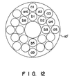
- Figs. 7 and 12 show concave transducers in these stone disintegration apparatus and hyperthermia apparatus.
- Fig. 8 shows a positional relationship between a living body and an applicator in the stone disintegration apparatus or the hyperthermia apparatus.
- Figs. 9 to 11 respectively show display forms for displaying the intensities of reception signals in the stone disintegration apparatus or the hyperthermia apparatus.
- the components for stone disintegration shown in Fig. 1 includes a concave transducer 10 as an electroacoustic transducer element, a driving system 20 including pulsers 22 (22-1 - 22-20), a receiving system including limiters 32 (32-1 - 32-20), preamplifiers 34 (34-1 to 34-20), signal processing circuits 36 (36-1 to 36-20), and a summing processing circuit 38, a DSC 40 including a freeze button 40A, a monitor 50, and a control system 60 (60A) including a rate pulse generator 62 and a controller 64.
- a concave transducer 10 as an electroacoustic transducer element
- a driving system 20 including pulsers 22 (22-1 - 22-20)
- a receiving system including limiters 32 (32-1 - 32-20), preamplifiers 34 (34-1 to 34-20), signal processing circuits 36 (36-1 to 36-20), and a summing processing circuit 38
- a DSC 40 including a freeze button 40A
- a monitor 50
- a stone disintegration apparatus shown in Fig. 3 comprises the components for stone disintegration, which includes the concave transducer 10, the driving system 20, the receiving system 30, the DSC 40, the monitor 50, and the control system 60 (60A) shown in Fig. 1, and a tomographic imaging system for imaging a sector tomographic image (B mode image), which includes an image ultrasonic probe 70, a transmitting system 72, a DSC 76, a monitor 78, and an imaging controller 60B.
- the concave transducer 10 is constituted by, e.g., a piezoelectric element having a concave surface and is arranged in an applicator 12 shown in Fig. 3 or 8.
- the concave transducer 10 is driven by the pulser 22 to emit a strong ultrasonic pulse (shock wave) or a weak ultrasonic pulse.
- the concave transducer 10 consists of two annular members, which are in contact with each other. These annular members are divided into a plurality of different partial transducers. For example, the outside annular member of the concave transducer 10 is divided into 12 equal portions (a1, a2, a12), while the inside annular member is divided into 8 equal portions (b1, b2, ... b8). That is, the concave transducer 10 is divided into 20 portions as a whole. These partial transducers (a1 - a12, b1 - b8) are electrically connected to the pulsers 22 constituting the driving system 20 and to the limiters 32, each serving as an element of the reception system 30.
- the applicator 12 is equipped with the concave transducer 10, a medium, e.g., water 14, a rubber film 16 for sealing the water 14, the ultrasonic probe 70, a mechanism (not shown) for operating the ultrasonic probe 70, and the like.
- a medium e.g., water 14
- a rubber film 16 for sealing the water 14
- the ultrasonic probe 70 a mechanism (not shown) for operating the ultrasonic probe 70, and the like.
- a strong ultrasonic pulse emitted from the concave transducer 10 propagates to a kidney 82 through the water 14, the rubber film 16, and a body surface 80A of a living body 80.
- the ultrasonic wave propagates in the form of a cone. That is, the sectional plane of the wave is wide near the concave transducer 10 and gradually narrows toward a stone 84. This is because the transducer 10 has a concave sound wave emission surface and is constituted by an annular member.
- the ultrasonic probe 70 is inserted in a hole in the center of the concave transducer 10 and is sector-scanned by the transmitting system 72 to monitor the position of the stone 84 existing in the kidney 82.
- sector scanning of the ultrasonic probe 70 is performed, a tomographic image of a sectorial plane or slice 72 around the stone 84 in the kidney 82 can be obtained on the monitor 78.
- the sectional plane 72 of sector scanning by the ultrasonic probe 70 gradually broadens downward to constitute a sectorial plane.
- the rate pulse generator 62 generates a rate pulse of several Hz and supplies it to each pulser 22.
- the pulsers 22 constituting the driving system 20 drive the respective partial transducers (a1 - b8) arranged on the concave transducer 10 in response to the rate pulse supplied from the rate pulse generator 62.
- the partial transducers (a1 - b8) are respectively driven by the pulsers 22 to emit ultrasonic pulses.
- the ultrasonic pulses propagate in the living body 80.
- the controller 64 supplies signals for controlling outputs from the pulsers 22.
- the controller 64 controls the following modes: a large output pulse mode for generating a strong ultrasonic pulse; a partially large output pulse mode for causing only some of the partial transducers to generate strong ultrasonic pulses; a small output pulse mode for generating weak ultrasonic pulses for monitoring; a selective driving mode for selectively driving the partial transducers; and a stop mode for stopping a pulse output operation.
- the respective partial transducers a1 to a8 detect ultrasonic waves reflected by the living body 80 and output electrical signals to the preamplifier 34 through the limiters 32.
- Each limiter 32 performs a limiting operation with respect to the echo signal input from a corresponding partial transducer so as to obtain only a desired signal component.
- Each preamplifier 34 amplifies the desired echo signal component input from a corresponding limiter 32 to a predetermined level.
- Each signal processing circuit 36 detects the amplified signal input from a corresponding preamplifier 34 by using an envelope detector, performs level adjustment of an obtained signal for a tomographic image, further performs signal processing such as A/D conversion (analog/digital conversion), and supplies the processed signal to the DSC (digital scan converter) 40.
- the DSC 40 has a frame memory and writes the processed signal, input from each signal processing circuit 36, in the frame memory. More specifically, the DSC 40 writes the respective processed signals in the frame memory by using address signals (not shown) in correspondence with the respective partial transducers, thus forming image patterns shown in Figs. 9 to 11. In addition, the DSC 40 converts the scan format of each processed signal written in the frame memory from the ultrasonic scan format to, e.g., the standard TV scan format, and, at the same time, supplies the image pattern shown in Fig. 9 to the monitor 50.
- the controller 64 is set in the stop mode, and a bag 16 of the applicator 12 is brought into contact with the body surface 80A of the living body 80. Subsequently, sector scanning is performed by the ultrasonic probe 70 to display a tomographic image on the monitor 78 shown in Fig. 3. Furthermore, the applicator 12 is moved to superpose an image of the stone 84 on the tomographic image. The position and angle of the applicator 12 are then set to position the focal point of the concave transducer 10 on the stone 84.
- the controller 64 is set in the small output pulse mode so that the partial transducers a1 to b8 are respectively driven by the pulsers 22 to emit weak ultrasonic pulses. Ultrasonic waves reflected by the living body 80 and received by the partial transducers a1 to b8 are added/processed by the addition processing circuit 38. The obtained signal is output to the monitor 50 through the DSC 40. As a result, reflection caused by the stone 84 can be detected through the monitor 50.
- reflected wave signals received by the partial transducers a1 to b8 reflectively pass through the pulsers 22, limiters 32, the preamplifiers 34, and the signal processing circuits 36 and are input to the DSC 40. These signals are then displayed on the monitor 50 by various display schemes.
- a first display pattern displayed on the monitor 50 will be described later.
- the intensities of waves reflected by the stone 84 are subjected to luminance modulation in the signal processing circuits 36.
- the modulated signals are then written in the DSC 40 in correspondence with the positions of the partial transducers a1 to b8.
- Reflected wave data is read out from the DSC 40 to be displayed on the monitor 50 in correspondence with the levels of luminance (brightness).
- weak reflected wave outputs such as wave outputs a6', a8', a10', and a11', or a9', are detected in accordance with the sizes and qualities of the obstacles.
- the luminances of portions, of the display pattern on the monitor 50, corresponding to the transducers which receive the weak reflected waves are decreased.
- a flicker display scheme may be employed, in which the frequency of flicker is increased with a decrease in reflection intensity.
- each partial transducer is required to have an area (opening) large enough to ensure a sufficient focusing effect so that ultrasonic waves from the respective partial transducers propagate in their own paths without overlapping much.
- a second display pattern of the intensities of waves reflected by the stone 84 will be described below with reference to Fig. 10.
- the amplitudes of signals received by the partial transducers a1 to b8 are properly processed by the signal processing circuits 36, and the obtained outputs are plotted along the axis of ordinate of the monitor 50.
- time t after the emission of a pulse i.e., a distance from a partial transducer, is set on the axis of abscissa of the monitor 50. With this setting, the intensity of a reflected wave received by each partial transducer is displayed. In the case shown in Fig.
- the third display pattern includes a pattern of the concave transducer, which is viewed from its upper surface, and a perspective pattern obtained by viewing the propagation paths of ultrasonic waves between the concave transducer and the stone or the focal point F0 when viewed from the side of the perspective pattern.
- the third display pattern may be constituted by only the pattern obtained by viewing the propagation paths, of ultrasonic waves, between the concave transducer and the stone or the focal point F0.
- the propagation paths of ultrasonic waves are divided into regions (T1 - F0), (T2 - F0), ... (T6 - F0).
- the intensities of ultrasonic waves shown in Fig. 9 are luminance-modulated in units of the divided paths and are displayed on the monitor 50. In this case, a substantially perspective image is displayed. For example, therefore, an addition average signal based on the area ratios of signals received by the partial transducers a2, a3, a4, and a5, which fall within a region T1, is used for the regions (T1 - F0).
- the regions T1, ... T6 may be divided into smaller regions.
- a large obstacle exists midway along the path on the left end in relation to an observer (the path of the partial transducer a9), strong reflection is indicated at the corresponding portion, and the reflection is weakened in the subsequent portion of the path, i.e., from the obstacle to the focal point F0.
- the perspective display pattern in Fig. 11 which is obtained by viewing the propagation paths, is displayed while superposing it on a tomographic image obtained by the ultrasonic probe, a relationship between an organ and the path of a radiated ultrasonic wave can be easily detected.
- These superposed images can be intermittently frozen by the freeze button 40A shown in Fig. 1 so as to prevent wasteful emission of ultrasonic waves.
- the applicator 12 can be set at an optimal position, in relation to the living body, at which only a few obstacles are present.
- the focal point is matched with the stone, and the display patterns in Figs. 9 to 11 are displayed.
- An optimal applicator position where the focal point always coincides with the stone can be easily set by rotating a support mechanism (not shown) of the applicator 12 about the focal position. After the optimal position is determined in this manner, the controller 64 is set in the large output pulse mode to emit strong ultrasonic waves.
- the controller 64 is set in the partial large output pulse mode to stop emission of strong ultrasonic waves from partial transducers corresponding to the path in which the obstacle is present and to cause other partial transducers to emit strong ultrasonic waves.
- This operation may be manually performed. However, driving of the corresponding partial transducers can be automatically stopped on a condition that the intensities of waves reflected by the stone, which are shown in, e.g., Fig. 9 or 10, are equal to or lower than a predetermined value.
- each partial transducer may be constituted by a combination of a plurality of transducers. If one partial transducer is constituted by a combination of smaller transducers, the degree of freedom in combination is greatly increased to allow finer control.
- the above-described embodiment is associated with the method of independently receiving reception signals in units of partial transducers.
- the directivity of transmission is the same as that of reception, the same effect as described above can be obtained by independently transmitting signals from the respective partial transducers.
- the partial transducers a1, a2, ... are sequentially driven by the controller 64 in the small output pulse mode.
- a reflected wave may be received by a corresponding partial transducer at each driving operation, or may be received by all the transducer, and the received waves are used as signals respectively corresponding to the paths of the partial transducers.
- stone disintegration is exemplified.
- the present invention is not limited to stone disintegration and can be equally applied to, e.g., an ultrasonic hyperthermia treatment and a treatment for cancer by strong ultrasonic waves.
- a strong ultrasonic wave may be a pulse wave or a continuous wave. This will be described later.
- a piezoelectric transducer is exemplified as a means for generating a strong ultrasonic wave.
- an element based on electromagnetic induction may be used.
- Such an element is designed such that a metal plate is placed on a spiral coil. When a large current is instantaneously supplied to the coil, a shock wave is generated from a surface of the metal plate. Therefore, the same arrangement as that of the concave transducer shown in Fig. 1 can be realized by using a plurality of such elements as partial transducers.
- reception signals received by a plurality of electromagnetic induction partial transducers may be used.
- piezoelectric elements may be arranged between the partial transducers, and a combination thereof may be used.
- the intensities of reflected waves are displayed in correspondence with luminance modulation.
- the intensities of reflected waves may be displayed by, e.g., a color display scheme.
- this stone disintegration apparatus is designed to radiate a shock wave on an upper portion of a living body and, more specifically, a system for independently controlling a section for stone disintegration and a section for ultrasonic imaging.
- An applicator 12 is arranged in a living body 80.
- the system includes a convex electroacoustic transducer element controller 60A and an imaging controller 60B.
- a stone disintegration apparatus specified by Figs. 1 and 4 is designed to radiate a shock wave on a lower portion of a living body and, more specifically, a system for independently controlling a section for stone disintegration and a section for ultrasonic imaging.
- An applicator 12 is arranged under a living body 80.
- the system includes a concave electroacoustic transducer element controller 60A and an imaging controller 60B.
- a stone disintegration apparatus specified by Figs. 1 and 5 is designed to radiate a shock wave on an upper portion of a living body and, more specifically, a system for collectively controlling a section for stone disintegration and a section for ultrasonic imaging.
- An applicator 12 is arranged on a living body 80.
- the system includes a collective control system 60'.
- a stone disintegration apparatus specified by Figs. 1 and 6 is designed to radiate a shock wave on a lower portion of a living body and, more specifically, a system for collectively controlling a section for stone disintegration and a section for ultrasonic imaging.
- An applicator 12 is arranged under a living body.
- the system includes a main control system 60'.
- Fig. 2 is a block diagram showing only components, of a hyperthermia apparatus, associated with a hyperthermia treatment, as an embodiment of the acoustic medical treatment apparatus according to the present invention.
- the pulsers 22 constituting the driving system 20 in Fig. 1 are replaced by continuous wave generation drivers 24, thus constituting a section for a hyperthermia treatment.
- Figs. 2 and 3 show an overall arrangement of the hyperthermia apparatus.
- this hyperthermia apparatus is designed to radiate a continuous wave or a burst wave on an upper portion of a living body and, more specifically, a system for independently controlling a section for a hyperthermia treatment and a section for ultrasonic imaging.
- An applicator 12 is arranged on a living body 80.
- the system incudes a concave electroacoustic transducer element controller 60A and an imaging controller 60B.
- a hyperthermia apparatus specified by Figs. 2 and 4 is designed to radiate a continuous wave or a burst wave on a lower portion of a living body and, more specifically, a system for independently controlling a section for a hyperthermia treatment and a section for ultrasonic imaging.
- An applicator 12 is arranged under a living body 80.
- the system includes a concave electroacoustic transducer element controller 60A and an imaging controller 60B.
- a hyperthermia apparatus specified by Figs. 2 and 5 is designed to radiate a continuous wave on an upper portion of a living body and, more specifically, a system for collectively controlling a section for a hyperthermia treatment and a section for ultrasonic imaging.
- An applicator 12 is arranged on a living body 80.
- the system includes a main control system 60'.
- a hyperthermia apparatus specified by Figs. 2 and 6 is designed to radiate a continuous wave on a lower portion of a living body and, more specifically, a system for collectively controlling a section for a hyperthermia treatment and a section for ultrasonic imaging.
- An applicator 12 is arranged under a living body 80.
- the system includes a main control system 60'.
- Each of the hyperthermia apparatuses respectively specified by Figs. 2 and 3, Figs. 2 and 4, Figs. 2 and 5, and Figs. 2 and 6 may use the concave transducer shown in Fig. 7 or 12.
- Fig. 8 shows a positional relationship between a living body and the applicator in each of the hyperthermia apparatuses.
- the display forms shown in Figs. 9 to 11 can be used as display forms for displaying the intensities of reception signals in these hyperthermia apparatuses.
- a transducer is divided into a plurality of partial transducers. Weak ultrasonic waves are respectively emitted from these partial transducers, and the reflected waves are respectively detected by the partial transducers to be displayed. Therefore, the state of a propagation path connecting each partial transducer to a focal point can be easily detected, thus eliminating blind regions.
- a shock wave or a continuous wave for medical treatment can be emitted after an optimal propagation path is easily selected and confirmed, thereby providing an acoustic medical treatment apparatus using an electroacoustic transducer element, which can greatly reduce the adverse effects, of unnecessary reflection of waves by a bone, a lung, or an intestinal gas, on a patient, and a pain in a living body, can enhance the safety, and allows efficient medical treatment.
Landscapes
- Health & Medical Sciences (AREA)
- Life Sciences & Earth Sciences (AREA)
- Surgery (AREA)
- Nuclear Medicine, Radiotherapy & Molecular Imaging (AREA)
- Medical Informatics (AREA)
- General Health & Medical Sciences (AREA)
- Veterinary Medicine (AREA)
- Engineering & Computer Science (AREA)
- Biomedical Technology (AREA)
- Heart & Thoracic Surgery (AREA)
- Radiology & Medical Imaging (AREA)
- Molecular Biology (AREA)
- Animal Behavior & Ethology (AREA)
- Public Health (AREA)
- Vascular Medicine (AREA)
- Orthopedic Medicine & Surgery (AREA)
- Gynecology & Obstetrics (AREA)
- Physics & Mathematics (AREA)
- Biophysics (AREA)
- Pathology (AREA)
- Surgical Instruments (AREA)
- Thermotherapy And Cooling Therapy Devices (AREA)
- Ultra Sonic Daignosis Equipment (AREA)
Applications Claiming Priority (2)
| Application Number | Priority Date | Filing Date | Title |
|---|---|---|---|
| JP2045496A JPH03251240A (ja) | 1990-02-28 | 1990-02-28 | 超音波治療装置 |
| JP45496/90 | 1990-02-28 |
Publications (2)
| Publication Number | Publication Date |
|---|---|
| EP0444680A1 true EP0444680A1 (de) | 1991-09-04 |
| EP0444680B1 EP0444680B1 (de) | 1998-06-10 |
Family
ID=12721009
Family Applications (1)
| Application Number | Title | Priority Date | Filing Date |
|---|---|---|---|
| EP91103034A Expired - Lifetime EP0444680B1 (de) | 1990-02-28 | 1991-02-28 | Vorrichtung für medizinische Behandlungen unter Verwendung von elektroakustischen Wandlern |
Country Status (4)
| Country | Link |
|---|---|
| US (1) | US5448994A (de) |
| EP (1) | EP0444680B1 (de) |
| JP (1) | JPH03251240A (de) |
| DE (1) | DE69129556T2 (de) |
Cited By (2)
| Publication number | Priority date | Publication date | Assignee | Title |
|---|---|---|---|---|
| WO1993014712A1 (fr) * | 1992-01-28 | 1993-08-05 | Technomed International | Appareil de traitement d'une cible, telle qu'une lesion utilisant un element marqueur |
| FR2700939A1 (fr) * | 1993-01-29 | 1994-08-05 | Siemens Ag | Appareil de thérapie pour la localisation et le traitement, à l'aide d'ondes acoustiques, d'une zone située dans le corps d'un être vivant. |
Families Citing this family (38)
| Publication number | Priority date | Publication date | Assignee | Title |
|---|---|---|---|---|
| US6023632A (en) | 1997-07-16 | 2000-02-08 | Wilk; Peter J. | Ultrasonic medical system and associated method |
| US7497828B1 (en) | 1992-01-10 | 2009-03-03 | Wilk Ultrasound Of Canada, Inc. | Ultrasonic medical device and associated method |
| US5899857A (en) * | 1997-01-07 | 1999-05-04 | Wilk; Peter J. | Medical treatment method with scanner input |
| US7108663B2 (en) | 1997-02-06 | 2006-09-19 | Exogen, Inc. | Method and apparatus for cartilage growth stimulation |
| US7789841B2 (en) | 1997-02-06 | 2010-09-07 | Exogen, Inc. | Method and apparatus for connective tissue treatment |
| US5904659A (en) | 1997-02-14 | 1999-05-18 | Exogen, Inc. | Ultrasonic treatment for wounds |
| SE518490C2 (sv) * | 1997-04-18 | 2002-10-15 | Ultrazonix Dnt Ab | Anordning för icke-invasiv behandling av biologisk vävnad |
| US6319201B1 (en) | 1997-10-15 | 2001-11-20 | Peter J. Wilk | Imaging device and associated method |
| US7211060B1 (en) | 1998-05-06 | 2007-05-01 | Exogen, Inc. | Ultrasound bandages |
| US6585647B1 (en) | 1998-07-21 | 2003-07-01 | Alan A. Winder | Method and means for synthetic structural imaging and volume estimation of biological tissue organs |
| US6139499A (en) * | 1999-02-22 | 2000-10-31 | Wilk; Peter J. | Ultrasonic medical system and associated method |
| KR100803810B1 (ko) | 1999-05-21 | 2008-02-14 | 엑조겐 인코포레이티드 | 초음파 및 전자기적으로 조직을 치료하는 장치 |
| EP1408853A1 (de) | 1999-06-14 | 2004-04-21 | Exogen, Inc. | Verfahren und kit durch kavitten ausgelöste gewebeheilung mittels ultraschall niedriger intensität |
| US6692450B1 (en) * | 2000-01-19 | 2004-02-17 | Medtronic Xomed, Inc. | Focused ultrasound ablation devices having selectively actuatable ultrasound emitting elements and methods of using the same |
| US6595934B1 (en) * | 2000-01-19 | 2003-07-22 | Medtronic Xomed, Inc. | Methods of skin rejuvenation using high intensity focused ultrasound to form an ablated tissue area containing a plurality of lesions |
| US8221402B2 (en) | 2000-01-19 | 2012-07-17 | Medtronic, Inc. | Method for guiding a medical device |
| US7706882B2 (en) | 2000-01-19 | 2010-04-27 | Medtronic, Inc. | Methods of using high intensity focused ultrasound to form an ablated tissue area |
| US6517484B1 (en) | 2000-02-28 | 2003-02-11 | Wilk Patent Development Corporation | Ultrasonic imaging system and associated method |
| US6932308B2 (en) | 2000-10-25 | 2005-08-23 | Exogen, Inc. | Transducer mounting assembly |
| US6807968B2 (en) | 2001-04-26 | 2004-10-26 | Medtronic, Inc. | Method and system for treatment of atrial tachyarrhythmias |
| US7846096B2 (en) * | 2001-05-29 | 2010-12-07 | Ethicon Endo-Surgery, Inc. | Method for monitoring of medical treatment using pulse-echo ultrasound |
| US20030013972A1 (en) | 2001-05-29 | 2003-01-16 | Makin Inder Raj. S. | Treatment of lung lesions using ultrasound |
| US7211044B2 (en) | 2001-05-29 | 2007-05-01 | Ethicon Endo-Surgery, Inc. | Method for mapping temperature rise using pulse-echo ultrasound |
| FR2827149B1 (fr) * | 2001-07-13 | 2003-10-10 | Technomed Medical Systems | Sonde de traitement par ultrasons focalises |
| US7429248B1 (en) | 2001-08-09 | 2008-09-30 | Exogen, Inc. | Method and apparatus for controlling acoustic modes in tissue healing applications |
| US7285094B2 (en) | 2002-01-30 | 2007-10-23 | Nohara Timothy J | 3D ultrasonic imaging apparatus and method |
| US7494467B2 (en) | 2004-04-16 | 2009-02-24 | Ethicon Endo-Surgery, Inc. | Medical system having multiple ultrasound transducers or an ultrasound transducer and an RF electrode |
| WO2005112812A1 (en) | 2004-05-14 | 2005-12-01 | Medtronic, Inc. | Method and devices for treating atrial fibrillation by mass ablation |
| US7883468B2 (en) * | 2004-05-18 | 2011-02-08 | Ethicon Endo-Surgery, Inc. | Medical system having an ultrasound source and an acoustic coupling medium |
| US7951095B2 (en) | 2004-05-20 | 2011-05-31 | Ethicon Endo-Surgery, Inc. | Ultrasound medical system |
| US7473250B2 (en) | 2004-05-21 | 2009-01-06 | Ethicon Endo-Surgery, Inc. | Ultrasound medical system and method |
| US7806839B2 (en) * | 2004-06-14 | 2010-10-05 | Ethicon Endo-Surgery, Inc. | System and method for ultrasound therapy using grating lobes |
| US7914454B2 (en) * | 2004-06-25 | 2011-03-29 | Wilk Ultrasound Of Canada, Inc. | Real-time 3D ultrasonic imaging apparatus and method |
| US7530958B2 (en) * | 2004-09-24 | 2009-05-12 | Guided Therapy Systems, Inc. | Method and system for combined ultrasound treatment |
| US7833221B2 (en) | 2004-10-22 | 2010-11-16 | Ethicon Endo-Surgery, Inc. | System and method for treatment of tissue using the tissue as a fiducial |
| US7452357B2 (en) | 2004-10-22 | 2008-11-18 | Ethicon Endo-Surgery, Inc. | System and method for planning treatment of tissue |
| US20080039746A1 (en) | 2006-05-25 | 2008-02-14 | Medtronic, Inc. | Methods of using high intensity focused ultrasound to form an ablated tissue area containing a plurality of lesions |
| US12357531B2 (en) | 2021-10-27 | 2025-07-15 | Curative Sound, LLC | Handheld focused extracorporeal shock wave therapy device, kit, and method |
Citations (3)
| Publication number | Priority date | Publication date | Assignee | Title |
|---|---|---|---|---|
| EP0133946A2 (de) * | 1983-08-03 | 1985-03-13 | Siemens Aktiengesellschaft | Einrichtung zum berührungslosen Zertrümmern von Konkrementen |
| GB2187840A (en) * | 1986-03-11 | 1987-09-16 | Wolf Gmbh Richard | Method and apparatus for detecting cavitations during medical application of high sonic energy |
| DE3736733A1 (de) * | 1986-10-29 | 1988-05-11 | Olympus Optical Co | Ultraschall-therapievorrichtung |
Family Cites Families (5)
| Publication number | Priority date | Publication date | Assignee | Title |
|---|---|---|---|---|
| US4803995A (en) * | 1986-06-27 | 1989-02-14 | Kabushiki Kaisha Toshiba | Ultrasonic lithotrity apparatus |
| EP0316863B2 (de) * | 1987-11-16 | 2000-11-29 | Kabushiki Kaisha Toshiba | Stosswellenbehandlungseinrichtung |
| US4955366A (en) * | 1987-11-27 | 1990-09-11 | Olympus Optical Co., Ltd. | Ultrasonic therapeutical apparatus |
| US4962754A (en) * | 1988-01-13 | 1990-10-16 | Kabushiki Kaisha Toshiba | Shock wave treatment apparatus |
| JP2602923B2 (ja) * | 1988-10-31 | 1997-04-23 | 株式会社東芝 | 衝撃波治療装置 |
-
1990
- 1990-02-28 JP JP2045496A patent/JPH03251240A/ja active Pending
-
1991
- 1991-02-28 EP EP91103034A patent/EP0444680B1/de not_active Expired - Lifetime
- 1991-02-28 DE DE69129556T patent/DE69129556T2/de not_active Expired - Fee Related
-
1994
- 1994-06-06 US US08/254,665 patent/US5448994A/en not_active Expired - Lifetime
Patent Citations (3)
| Publication number | Priority date | Publication date | Assignee | Title |
|---|---|---|---|---|
| EP0133946A2 (de) * | 1983-08-03 | 1985-03-13 | Siemens Aktiengesellschaft | Einrichtung zum berührungslosen Zertrümmern von Konkrementen |
| GB2187840A (en) * | 1986-03-11 | 1987-09-16 | Wolf Gmbh Richard | Method and apparatus for detecting cavitations during medical application of high sonic energy |
| DE3736733A1 (de) * | 1986-10-29 | 1988-05-11 | Olympus Optical Co | Ultraschall-therapievorrichtung |
Cited By (2)
| Publication number | Priority date | Publication date | Assignee | Title |
|---|---|---|---|---|
| WO1993014712A1 (fr) * | 1992-01-28 | 1993-08-05 | Technomed International | Appareil de traitement d'une cible, telle qu'une lesion utilisant un element marqueur |
| FR2700939A1 (fr) * | 1993-01-29 | 1994-08-05 | Siemens Ag | Appareil de thérapie pour la localisation et le traitement, à l'aide d'ondes acoustiques, d'une zone située dans le corps d'un être vivant. |
Also Published As
| Publication number | Publication date |
|---|---|
| US5448994A (en) | 1995-09-12 |
| DE69129556D1 (de) | 1998-07-16 |
| DE69129556T2 (de) | 1999-03-04 |
| JPH03251240A (ja) | 1991-11-08 |
| EP0444680B1 (de) | 1998-06-10 |
Similar Documents
| Publication | Publication Date | Title |
|---|---|---|
| EP0444680B1 (de) | Vorrichtung für medizinische Behandlungen unter Verwendung von elektroakustischen Wandlern | |
| EP0514010B1 (de) | Vorrichtung zum Zerstören von Konkrementen | |
| EP0170416B1 (de) | Ultraschall-Hyperthermieapparat | |
| US5048527A (en) | Shock wave treatment apparatus | |
| US5005580A (en) | Destroying wave treatment apparatus | |
| EP0336620B1 (de) | Nierensteinzertrümmerer | |
| EP0460536A1 (de) | Vorrichtung für Lithotripsie | |
| JP3065634B2 (ja) | 衝撃波治療装置及び温熱治療装置 | |
| WO2003028556A1 (en) | Ultrasonic diagnosing device and ultrsonic diagnosing method | |
| US4926857A (en) | Device for treating life forms with two different types of focused acoustical waves | |
| JP3378308B2 (ja) | 超音波診断装置 | |
| US4986259A (en) | Apparatus and method for disintegrating calculus | |
| JPS6249843A (ja) | 超音波結石破砕装置 | |
| JP3145084B2 (ja) | 超音波治療装置 | |
| EP0461479B1 (de) | Lithotripsievorrichtung mit Funktion zur Verhinderung eines Fehlschusses | |
| JPH02104343A (ja) | 超音波治療装置 | |
| JP3142535B2 (ja) | 超音波治療装置 | |
| JPS6247358A (ja) | 超音波刺激装置 | |
| US20050228319A1 (en) | Neoplasm cell destruction device | |
| JPH07231895A (ja) | 超音波治療装置 | |
| JP3350531B2 (ja) | 結石破砕装置 | |
| JPH0531119A (ja) | 超音波結石破砕装置 | |
| JPH01181858A (ja) | 衝撃波治療装置 | |
| JPH0438944A (ja) | 衝撃波治療装置及び温熱治療装置 | |
| JPH0435655A (ja) | 結石破砕装置 |
Legal Events
| Date | Code | Title | Description |
|---|---|---|---|
| PUAI | Public reference made under article 153(3) epc to a published international application that has entered the european phase |
Free format text: ORIGINAL CODE: 0009012 |
|
| 17P | Request for examination filed |
Effective date: 19910228 |
|
| AK | Designated contracting states |
Kind code of ref document: A1 Designated state(s): DE FR |
|
| 17Q | First examination report despatched |
Effective date: 19940713 |
|
| GRAG | Despatch of communication of intention to grant |
Free format text: ORIGINAL CODE: EPIDOS AGRA |
|
| GRAG | Despatch of communication of intention to grant |
Free format text: ORIGINAL CODE: EPIDOS AGRA |
|
| GRAH | Despatch of communication of intention to grant a patent |
Free format text: ORIGINAL CODE: EPIDOS IGRA |
|
| GRAH | Despatch of communication of intention to grant a patent |
Free format text: ORIGINAL CODE: EPIDOS IGRA |
|
| GRAA | (expected) grant |
Free format text: ORIGINAL CODE: 0009210 |
|
| AK | Designated contracting states |
Kind code of ref document: B1 Designated state(s): DE FR |
|
| REF | Corresponds to: |
Ref document number: 69129556 Country of ref document: DE Date of ref document: 19980716 |
|
| ET | Fr: translation filed | ||
| PLBE | No opposition filed within time limit |
Free format text: ORIGINAL CODE: 0009261 |
|
| STAA | Information on the status of an ep patent application or granted ep patent |
Free format text: STATUS: NO OPPOSITION FILED WITHIN TIME LIMIT |
|
| 26N | No opposition filed | ||
| PGFP | Annual fee paid to national office [announced via postgrant information from national office to epo] |
Ref country code: DE Payment date: 19991231 Year of fee payment: 10 |
|
| PGFP | Annual fee paid to national office [announced via postgrant information from national office to epo] |
Ref country code: FR Payment date: 20000210 Year of fee payment: 10 |
|
| PG25 | Lapsed in a contracting state [announced via postgrant information from national office to epo] |
Ref country code: FR Free format text: LAPSE BECAUSE OF NON-PAYMENT OF DUE FEES Effective date: 20011031 |
|
| REG | Reference to a national code |
Ref country code: FR Ref legal event code: ST |
|
| PG25 | Lapsed in a contracting state [announced via postgrant information from national office to epo] |
Ref country code: DE Free format text: LAPSE BECAUSE OF NON-PAYMENT OF DUE FEES Effective date: 20011201 |