EP0444737B1 - Dispositif pour la lecture par balayage d'une radiographie - Google Patents
Dispositif pour la lecture par balayage d'une radiographie Download PDFInfo
- Publication number
- EP0444737B1 EP0444737B1 EP91200358A EP91200358A EP0444737B1 EP 0444737 B1 EP0444737 B1 EP 0444737B1 EP 91200358 A EP91200358 A EP 91200358A EP 91200358 A EP91200358 A EP 91200358A EP 0444737 B1 EP0444737 B1 EP 0444737B1
- Authority
- EP
- European Patent Office
- Prior art keywords
- image
- values
- image memory
- signal processor
- buffered
- Prior art date
- Legal status (The legal status is an assumption and is not a legal conclusion. Google has not performed a legal analysis and makes no representation as to the accuracy of the status listed.)
- Expired - Lifetime
Links
- 238000002601 radiography Methods 0.000 title 1
- 230000006870 function Effects 0.000 claims description 40
- 239000000523 sample Substances 0.000 claims description 9
- 238000000034 method Methods 0.000 claims description 8
- 230000000694 effects Effects 0.000 claims description 7
- 239000000872 buffer Substances 0.000 claims 2
- 230000002238 attenuated effect Effects 0.000 claims 1
- 238000006073 displacement reaction Methods 0.000 claims 1
- 238000001914 filtration Methods 0.000 description 21
- 238000010586 diagram Methods 0.000 description 3
- 230000001419 dependent effect Effects 0.000 description 2
- 238000013461 design Methods 0.000 description 2
- 230000035945 sensitivity Effects 0.000 description 2
- 238000012937 correction Methods 0.000 description 1
- 230000006735 deficit Effects 0.000 description 1
- 238000011161 development Methods 0.000 description 1
- 239000011159 matrix material Substances 0.000 description 1
- 230000003446 memory effect Effects 0.000 description 1
- 238000012545 processing Methods 0.000 description 1
- 230000005855 radiation Effects 0.000 description 1
Images
Classifications
-
- H—ELECTRICITY
- H04—ELECTRIC COMMUNICATION TECHNIQUE
- H04N—PICTORIAL COMMUNICATION, e.g. TELEVISION
- H04N1/00—Scanning, transmission or reproduction of documents or the like, e.g. facsimile transmission; Details thereof
- H04N1/40—Picture signal circuits
- H04N1/409—Edge or detail enhancement; Noise or error suppression
-
- H—ELECTRICITY
- H04—ELECTRIC COMMUNICATION TECHNIQUE
- H04N—PICTORIAL COMMUNICATION, e.g. TELEVISION
- H04N23/00—Cameras or camera modules comprising electronic image sensors; Control thereof
- H04N23/30—Cameras or camera modules comprising electronic image sensors; Control thereof for generating image signals from X-rays
Definitions
- the invention relates to an arrangement according to the preamble of claim 1.
- Such an arrangement is known from EP-A-0 342 760, DE-A-35 29 108 and from the references cited therein.
- the problem arises from different sensitivities of the individual electrometer probes, from different distances between the individual electrometer probes and the surface of the photoconductor, and from low-frequency noise in the amplifiers downstream of the probes, that stripes appear in the image generated from the image values, which occur in the second direction.
- the object of the present invention is to design an arrangement of the type mentioned at the outset in such a way that the stripes are largely suppressed without the image content being significantly affected thereby. This object is achieved by the measures specified in claim 1.
- the original image values stored in the first image memory are first processed with the aid of the signal processor in such a way that image values of respectively adjacent pixels of an image line are acted upon by a high-pass filter function.
- the image values obtained in this way are temporarily stored in the second image memory.
- a low-pass filter function is then applied to the image values of pixels adjacent in the scanning direction.
- These values obtained in this way are in turn temporarily stored in the second image memory, the previously temporarily stored values being able to be overwritten.
- the values stored in the second image memory after performing the low-pass filtering are finally subtracted from the original values stored in the first image memory.
- the high-pass filter function is realized by means of a low-pass filter function and vice versa.
- a low-pass filter function is initially used to generate a high-pass filter function can be provided after the execution of which the values thus generated are subtracted from the original values.
- the result is a high-pass filter function.
- two functions are carried out in succession, the new values calculated in the process being temporarily stored. Only after performing both functions are the values calculated in this way subtracted from the original values.
- the filtering in the scanning direction and then that in the line direction can be carried out first.
- the values stored in the second image memory are multiplied by a scaling factor before the subtraction from the image values stored in the first image memory, which scaling factor is used to adjust the strength of the filter effect.
- the degree of filtering described above can be adjusted by means of a scaling factor depending on the intended use or the streakiness of the scanned image. This can advantageously be done by applying a scaling factor to the image values stored in the second image memory prior to subtraction of the values stored in the first image memory, by means of which they can be reduced as desired, whereby the filter effect can be set.
- the size of the scaling factor is selected as a function of the image amplitude represented by the image values so that it is relatively small in strongly exposed image areas.
- the scaling factor can advantageously be dependent on the height of the image values, i.e. the image amplitude.
- the filtering is reduced with increasing image amplitude.
- the size of the scaling factor is selected as a function of the signal curve in the area around an image value such that the scaling factor is selected to be relatively small in the area of strong signal jumps.
- the scaling factor can also be selected as a function of the signal curve. For this purpose, the course of the signal is examined for several pixels lying next to one another. If a signal jump occurs in the pixel area to be calculated, the scaling factor can be selected to be small in this area, so that the signal jump is influenced as little as possible.
- the filter functions are carried out by means of two one-dimensional filter functions.
- the filter functions carried out in the local area per se represent two-dimensional filtering
- the filtering can advantageously be carried out by means of two one-dimensional filter functions, which can be implemented with less effort.
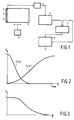
- FIG. 1 An arrangement shown schematically in FIG. 1 has a photoconductor 1 which has been charged uniformly before an X-ray exposure in a manner not shown in the figure and which is discharged as a function of the intensity of the X-ray radiation during an X-ray exposure. After this process, the surface of the photoconductor has been discharged to different extents, that is to say has a charge pattern.
- This charge pattern is scanned by means of several electrometer probes 2.
- a large number of electrometer probes are provided, which are provided in alignment in a row on a carrier 3 which is only indicated in the figure.
- a line of the charge pattern is first scanned, ie all the signals supplied by the sensors 2 are read out.
- the photoconductor 1 is then controlled by means of a device which is not shown in the figures a control unit 4 is moved relative to the sensors 2 by approximately the width of a scanning line in the scanning direction. This movement therefore runs perpendicular to the line direction, which runs parallel to the carrier 3 of the sensors 2.
- a line of the charge pattern located on the photoconductor 1 is again scanned by means of the electrometer probes 2. This process is repeated until the entire charge pattern has been scanned.
- the signals of the sensors 2 read out during the scanning process are optionally amplified and fed to an A / D converter 5.
- the data thus converted into the digital area are read into an image memory 6.
- the image values of all the pixels are stored in the image memory 6. If, for example, one of the sensors 2 now has a sensitivity that differs from the other sensors, the signals supplied by this sensor would be larger or smaller than the signals supplied by the other sensors. As a result, however, this means nothing other than that streaking in the scanning direction, that is to say transversely to the line direction, occurs in an image which can be represented by reading out the signals stored in the image memory 6.
- Such streakiness could e.g. also arise from differing distances between the different probes and the photoconductor 1 or from low-frequency fluctuations (noise) of the probe signals.
- This streaking can now be at least reduced by applying a low-pass filter function to the image values of respectively adjacent pixels of an image line become.
- the image values in the scanning direction of adjacent pixels are acted upon by a high-pass filter function.
- the high-pass filter function is implemented by means of a low-pass filter function and vice versa.
- the high-pass filtering to be carried out between image values in the scanning direction of adjacent pixels can also be implemented in such a way that low-pass filtering is first carried out with the aid of the signal processor 7.
- the image values obtained in this way are first temporarily stored in a second image memory 8. This is followed by low-pass filtering of image values in each case in a bit line of adjacent pixels in such a way that a high-pass filter function is applied to the image values of these pixels.
- the calculated image values are in turn temporarily stored in the second image memory 8.
- the newly calculated image values obtained in this way, which are stored in the second image memory 8 are subtracted from the original image values stored in the first image memory 6 by means of the signal processor 7.
- the new image values obtained from this subtraction represent the filtered image values and are stored in the second image memory 8, from which these can now be found for further processing or for display on a monitor, for example.
- F s (z, a) the filter function and G (k) the scaling factor.
- This two-dimensional filtering can be carried out by means of two one-dimensional filtering.
- both filter functions are selected so that they do not influence the image values Sin in the extreme cases or suppress them completely.
- the selection of these filter functions depends on many parameters, such as the photoconductor used, the photosensors, the distance between the sensors and the photoconductors, the desired resolution, etc., and therefore cannot be given as generally applicable. 2 shows, however, that a high-pass filter function is applied to adjacent pixels in the line direction and that a low-pass filter function is applied to adjacent pixels in the scanning direction.
- the filter values subtracted from the originally determined image values, which are stored in the first image memory 6 according to FIG. 1, are additionally subjected to a scaling factor G (k) by means of which the degree of filtering can be influenced.
- the scaling factor G (k) can be selected in various ways.
- k max represents the maximum image amplitude.
- the factor k becomes larger with increasing image amplitude, so that the scaling factor G (k) becomes smaller with increasing image amplitude, so that the filter values subtracted from the original image values also become smaller, as a result of which the filter effect is reduced.
- both a current jump height and a jump height previously determined in the adjacent area d are taken into account.
- the effect is achieved that the filter effect is reduced in the area of relatively strong signal changes, but that a relatively large filter effect occurs in areas with small signal changes. In this way, image interference is particularly well suppressed in areas in which there is a high probability that no useful signal is present.
Landscapes
- Engineering & Computer Science (AREA)
- Multimedia (AREA)
- Signal Processing (AREA)
- Image Processing (AREA)
- Apparatus For Radiation Diagnosis (AREA)
- Facsimile Image Signal Circuits (AREA)
- Image Analysis (AREA)
- Transforming Light Signals Into Electric Signals (AREA)
- Facsimile Scanning Arrangements (AREA)
Claims (8)
- Dispositif de lecture par balayage d'une image de charges qui est produite sur un photoconducteur (1) chargé préalablement localement de manière uniforme pendant une exposition à des rayons X, en fonction de leur intensité locale, comportant :- un dispositif électrométrique (2, 3) avec plusieurs sondes électrométriques (2) disposées en une rangée définissant une première direction, ces sondes délivrant pour chaque point d'image une valeur d'image correspondant à la décharge;- une unité (4) pour produire un déplacement dans une deuxième direction perpendiculaire à la première direction entre le photoconducteur (1) et le dispositif électrométrique (2, 3) au cours du balayage de la configuration de charges par le dispositif électrométrique;- un convertisseur analogique/numérique (5) pour convertir les valeurs d'image, et- une mémoire d'image (6) pour stocker les valeurs d'image converties par le convertisseur analogique/numérique, et un processeur de signaux (7) traitant les valeurs d'image stockées,caractérisé en ce que le processeur de signaux (7) est conçu pour le filtrage des valeurs d'image stockées de manière à affaiblir les composantes de l'image qui présentent dans la première direction une fréquence locale haute et dans la deuxième direction une fréquence locale basse.
- Dispositif selon la revendication 1, caractérisé en ce que les fonctions de filtrage sont réalisées à l'aide du processeur de signaux (7) et d'une deuxième mémoire d'image (8) en soumettant les valeurs de signaux introduites dans la première mémoire d'image, à l'aide du processeur de signaux (7), dans la première direction, à une fonction de filtrage passe-haut et en les stockant temporairement dans la deuxième mémoire d'image (8), en soumettant, à l'aide du processeur de signaux (7), ces valeurs stockées temporairement, dans la deuxième direction, à une fonction de filtrage passe-bas et à nouveau en les stockant temporairement dans la deuxième mémoire d'image, et en soustrayant, après calcul de toutes les valeurs, les valeurs stockées temporairement dans la deuxième mémoire d'image (8) des valeurs stockées dans la première mémoire d'image (6).
- Dispositif selon la revendication 1, caractérisé en ce que les fonctions de filtrage sont réalisées à l'aide du processeur de signaux (7) et d'une deuxième mémoire d'image (8), par le fait que les valeurs de signaux introduites dans la première mémoire d'image, à l'aide du processeur de signaux (7), dans la deuxième direction, sont soumises à une fonction de filtrage passe-bas et sont stockées temporairement dans la deuxième mémoire d'image (8), par le fait que ces valeurs stockées temporairement, à l'aide du processeur de signaux (7), dans la première direction, sont soumises à une fonction de filtrage passe-haut et sont à nouveau stockées temporairement dans la deuxième mémoire d'image, par le fait qu'après le calcul de toutes les valeurs, les valeurs stockées temporairement dans la deuxième mémoire d'image (8) sont soustraites des valeurs mémorisées dans la première mémoire d'image (6).
- Dispositif selon la revendication 2 ou 3, caractérisé en ce que les valeurs stockées dans la deuxième mémoire d'image (8) sont, avant soustraction des valeurs d'image stockées dans la première mémoire d'image, à l'aide du processeur de signaux, multipliées par un facteur d'échelle qui sert à régler l'intensité de l'effet de filtrage.
- Dispositif selon la revendication 4, caractérisé en ce que l'ordre de grandeur du facteur d'échelle est choisi en fonction de l'amplitude de l'image représentée par les valeurs d'image, de telle sorte qu'il soit relativement petit dans les zones d'image fortement éclairées.
- Dispositif selon la revendication 4, caractérisé en ce que l'ordre de grandeur du facteur d'échelle est choisi en fonction de la variation du signal dans la zone entourant une valeur d'image, de telle sorte que le facteur d'échelle soit relativement petit dans la zone des sauts de signal importants.
- Dispositif selon l'une quelconque des revendications 1 à 6, caractérisé en ce que les fonctions de filtrage sont réalisées à l'aide de deux fonctions de filtrage unidimensionnelles.
- Appareil d'examen radiographique comportant une source pour produire des rayons X, caractérisé en ce qu'il est prévu un dispositif selon l'une quelconque des revendications précédentes pour la production d'une image radiographique.
Applications Claiming Priority (2)
| Application Number | Priority Date | Filing Date | Title |
|---|---|---|---|
| DE4006181 | 1990-02-28 | ||
| DE4006181A DE4006181A1 (de) | 1990-02-28 | 1990-02-28 | Anordnung zum abtasten einer roentgenaufnahme |
Publications (3)
| Publication Number | Publication Date |
|---|---|
| EP0444737A2 EP0444737A2 (fr) | 1991-09-04 |
| EP0444737A3 EP0444737A3 (en) | 1992-04-29 |
| EP0444737B1 true EP0444737B1 (fr) | 1995-08-16 |
Family
ID=6401074
Family Applications (1)
| Application Number | Title | Priority Date | Filing Date |
|---|---|---|---|
| EP91200358A Expired - Lifetime EP0444737B1 (fr) | 1990-02-28 | 1991-02-20 | Dispositif pour la lecture par balayage d'une radiographie |
Country Status (4)
| Country | Link |
|---|---|
| US (1) | US6058220A (fr) |
| EP (1) | EP0444737B1 (fr) |
| JP (1) | JP2962527B2 (fr) |
| DE (2) | DE4006181A1 (fr) |
Families Citing this family (6)
| Publication number | Priority date | Publication date | Assignee | Title |
|---|---|---|---|---|
| DE4330366A1 (de) * | 1993-09-08 | 1995-03-09 | Philips Patentverwaltung | Verfahren zum Erzeugen von Röntgenaufnahmen und Anordnung zur Durchführung des Verfahrens |
| GB0129390D0 (en) * | 2001-12-07 | 2002-01-30 | Clark Terrence D | Electrodynamic sensors and applications thereof |
| US8923956B2 (en) | 2001-12-07 | 2014-12-30 | The University Of Sussex | Electrodynamic sensors and applications thereof |
| US7426314B2 (en) * | 2004-07-30 | 2008-09-16 | Hewlett-Packard Development Company, L.P. | Adjusting pixels by desired gains and factors |
| US7860334B2 (en) * | 2006-02-09 | 2010-12-28 | Qualcomm Incorporated | Adaptive image filter for filtering image information |
| JP5538684B2 (ja) * | 2008-03-13 | 2014-07-02 | キヤノン株式会社 | 画像処理装置、画像処理方法、プログラム、及び記憶媒体 |
Family Cites Families (14)
| Publication number | Priority date | Publication date | Assignee | Title |
|---|---|---|---|---|
| US4328425A (en) * | 1980-08-04 | 1982-05-04 | Xerox Corporation | Filter for image pixels |
| DE3417386A1 (de) * | 1984-05-10 | 1985-11-14 | Siemens AG, 1000 Berlin und 8000 München | Fernseheinrichtung mit filtermitteln mit ortsfrequenter hochpasscharakteristik |
| US4677461A (en) * | 1984-07-26 | 1987-06-30 | Mitsubishi Denki Kabushiki Kaisha | Contour detecting filter |
| US4706113A (en) * | 1985-02-18 | 1987-11-10 | Mitsubishi Denki Kabushiki Kaisha | Contour detecting filter device using PAL samples of composite video signals without separation of luminance signals therefrom |
| DE3529108A1 (de) * | 1985-08-14 | 1987-02-26 | Philips Patentverwaltung Gmbh, 2000 Hamburg | Verfahren zur erzeugung einer roentgenaufnahme mittels eines fotoleiters und anordnung zur durchfuehrung des verfahrens |
| US4821337A (en) * | 1985-10-30 | 1989-04-11 | Alm Ake W | Radiation scanner uniformity system |
| US4789890A (en) * | 1985-12-05 | 1988-12-06 | Mitsubishi Denki Kabushiki Kaisha | Judgement circuit and adaptive filter incorporating the same |
| DE3629409C2 (de) * | 1986-08-29 | 1994-02-17 | Agfa Gevaert Ag | Verfahren und Vorrichtung zur Kontrastbewertung bei der elektronischen Bildverarbeitung |
| US4954885A (en) * | 1987-02-25 | 1990-09-04 | Mitsubishi Denki Kabushiki Kaisha | Filter for separating luminance and chrominance signals from composite color television signal |
| US4908697A (en) * | 1987-07-24 | 1990-03-13 | North American Philips Corporation | Two-line mac high definition television system |
| US4999701A (en) * | 1987-11-17 | 1991-03-12 | North American Philips Corporation | High definition NTSC compatible television system with increased horizontal bandwidth and reduced color artifacts |
| DE3817027A1 (de) * | 1988-05-19 | 1989-11-30 | Philips Patentverwaltung | Verfahren zur erzeugung einer roentgenaufnahme mittels eines photoleiters und anordnung zur durchfuehrung des verfahrens |
| US4912569A (en) * | 1989-01-24 | 1990-03-27 | Eastman Kodak Company | Method for thresholding an image signal |
| US5003618A (en) * | 1989-07-14 | 1991-03-26 | University Of Pittsburgh Of The Commonwealth System Of Higher Education | Automatic adaptive anisotropic digital filtering and biasing of digitized images |
-
1990
- 1990-02-28 DE DE4006181A patent/DE4006181A1/de not_active Withdrawn
-
1991
- 1991-02-20 EP EP91200358A patent/EP0444737B1/fr not_active Expired - Lifetime
- 1991-02-20 DE DE59106237T patent/DE59106237D1/de not_active Expired - Fee Related
- 1991-02-26 JP JP3030841A patent/JP2962527B2/ja not_active Expired - Lifetime
-
1993
- 1993-11-24 US US08/157,842 patent/US6058220A/en not_active Expired - Fee Related
Also Published As
| Publication number | Publication date |
|---|---|
| EP0444737A3 (en) | 1992-04-29 |
| US6058220A (en) | 2000-05-02 |
| EP0444737A2 (fr) | 1991-09-04 |
| JPH06103376A (ja) | 1994-04-15 |
| DE59106237D1 (de) | 1995-09-21 |
| JP2962527B2 (ja) | 1999-10-12 |
| DE4006181A1 (de) | 1991-08-29 |
Similar Documents
| Publication | Publication Date | Title |
|---|---|---|
| DE2952422C3 (de) | Verfahren und Vorrichtung zum Verarbeiten eines Röntgenbildes bei einem Röntgenbild-Kopiersystem | |
| DE69425416T2 (de) | Verfahren zur Bildzusammensetzung und Bilderzeugungsvorrichtung zur Durchführung dieses Verfahrens | |
| DE3826288C2 (fr) | ||
| DE69515646T2 (de) | Verfahren und Vorrichtung zum Erfassen von Fehlern in Textilbahnen und dergleichen | |
| DE3441165C2 (de) | Einrichtung zum Verstärken digitaler fluorographischer Bilder | |
| EP0212733B1 (fr) | Procédé et appareil pour la production d'images à rayons X par photoconducteur | |
| DE69011194T2 (de) | Röntgenstrahl-Bildverarbeitungsgerät. | |
| DE2804158C2 (fr) | ||
| EP0681269B1 (fr) | Appareil et procédé de réproduction d'une radiographie comme image visible | |
| DE69128954T2 (de) | Rechnertomographie | |
| DE3406905A1 (de) | Roentgengeraet | |
| DE3704685A1 (de) | Anordnung und verfahren zur korrektur bzw. kompensation von streustrahlung durch adaptive filterung | |
| DE19900298A1 (de) | Korrekturalgorithmus für knocheninduzierte spektrale Artefakte bei einer Computer-Tomographie-Abbildung | |
| DE69129868T2 (de) | Verfahren und Gerät zur Glättung von Bildern | |
| DE68927031T2 (de) | Verfahren zur Bestimmung der gewünschten Bereiche eines Bildsignals und Verfahren zur Bestimmung der gewünschten Bildbereiche | |
| DE2702009A1 (de) | Radiographisches geraet | |
| DE602005004410T2 (de) | System und verfahren zur korrektur zeitlicher artefakte in tomographischen bildern | |
| DE19601469A1 (de) | Z-Achsen-Gewinnkorrektur eines Detektors für ein CT-System | |
| DE2741732A1 (de) | Schichtgeraet zur herstellung von transversalschichtbildern | |
| DE2532716B2 (de) | Gerät zur Erzeugung einer Darstellung der Absorptionsverteilung einer Strahlung in einer Querschnittsscheibe eines Körpers | |
| EP0342760B1 (fr) | Méthode de production d'une image radiologique au moyen de photoconducteurs et dispositif de mise en oeuvre du procédé | |
| DE19860036C1 (de) | Verfahren zum Reduzieren von spalten- oder zeilenkorreliertem bzw. teilspalten- oder teilzeilenkorreliertem Rauschen bei einem digitalen Bildsensor sowie Vorrichtung zur Aufnahme von Strahlungsbildern | |
| EP0444737A2 (fr) | Dispositif pour la lecture par balayage d'une radiographie | |
| EP0558116B1 (fr) | Procédé pour radiographies et dispositif approprié | |
| EP0517302B1 (fr) | Installation de production de radiographies |
Legal Events
| Date | Code | Title | Description |
|---|---|---|---|
| PUAI | Public reference made under article 153(3) epc to a published international application that has entered the european phase |
Free format text: ORIGINAL CODE: 0009012 |
|
| AK | Designated contracting states |
Kind code of ref document: A2 Designated state(s): DE FR GB |
|
| PUAL | Search report despatched |
Free format text: ORIGINAL CODE: 0009013 |
|
| AK | Designated contracting states |
Kind code of ref document: A3 Designated state(s): DE FR GB |
|
| 17P | Request for examination filed |
Effective date: 19921029 |
|
| 17Q | First examination report despatched |
Effective date: 19940725 |
|
| GRAA | (expected) grant |
Free format text: ORIGINAL CODE: 0009210 |
|
| AK | Designated contracting states |
Kind code of ref document: B1 Designated state(s): DE FR GB |
|
| REF | Corresponds to: |
Ref document number: 59106237 Country of ref document: DE Date of ref document: 19950921 |
|
| GBT | Gb: translation of ep patent filed (gb section 77(6)(a)/1977) |
Effective date: 19951115 |
|
| ET | Fr: translation filed | ||
| PLBE | No opposition filed within time limit |
Free format text: ORIGINAL CODE: 0009261 |
|
| STAA | Information on the status of an ep patent application or granted ep patent |
Free format text: STATUS: NO OPPOSITION FILED WITHIN TIME LIMIT |
|
| 26N | No opposition filed | ||
| REG | Reference to a national code |
Ref country code: FR Ref legal event code: CD |
|
| PGFP | Annual fee paid to national office [announced via postgrant information from national office to epo] |
Ref country code: FR Payment date: 20000222 Year of fee payment: 10 |
|
| PGFP | Annual fee paid to national office [announced via postgrant information from national office to epo] |
Ref country code: GB Payment date: 20000228 Year of fee payment: 10 |
|
| PGFP | Annual fee paid to national office [announced via postgrant information from national office to epo] |
Ref country code: DE Payment date: 20000419 Year of fee payment: 10 |
|
| PG25 | Lapsed in a contracting state [announced via postgrant information from national office to epo] |
Ref country code: GB Free format text: LAPSE BECAUSE OF NON-PAYMENT OF DUE FEES Effective date: 20010220 |
|
| GBPC | Gb: european patent ceased through non-payment of renewal fee |
Effective date: 20010220 |
|
| PG25 | Lapsed in a contracting state [announced via postgrant information from national office to epo] |
Ref country code: FR Free format text: LAPSE BECAUSE OF NON-PAYMENT OF DUE FEES Effective date: 20011031 |
|
| REG | Reference to a national code |
Ref country code: FR Ref legal event code: ST |
|
| PG25 | Lapsed in a contracting state [announced via postgrant information from national office to epo] |
Ref country code: DE Free format text: LAPSE BECAUSE OF NON-PAYMENT OF DUE FEES Effective date: 20011201 |