EP0444985B1 - Double diffuser with flexible bellows and internal actuator - Google Patents
Double diffuser with flexible bellows and internal actuator Download PDFInfo
- Publication number
- EP0444985B1 EP0444985B1 EP91400279A EP91400279A EP0444985B1 EP 0444985 B1 EP0444985 B1 EP 0444985B1 EP 91400279 A EP91400279 A EP 91400279A EP 91400279 A EP91400279 A EP 91400279A EP 0444985 B1 EP0444985 B1 EP 0444985B1
- Authority
- EP
- European Patent Office
- Prior art keywords
- cylinder
- vessel
- pulp
- recited
- piston
- Prior art date
- Legal status (The legal status is an assumption and is not a legal conclusion. Google has not performed a legal analysis and makes no representation as to the accuracy of the status listed.)
- Expired - Lifetime
Links
- 238000007789 sealing Methods 0.000 claims abstract description 19
- 239000012530 fluid Substances 0.000 claims abstract description 18
- 239000007788 liquid Substances 0.000 claims description 16
- 238000004061 bleaching Methods 0.000 claims description 5
- 238000009792 diffusion process Methods 0.000 claims description 5
- 239000007921 spray Substances 0.000 claims description 5
- 238000000605 extraction Methods 0.000 claims description 4
- NJPPVKZQTLUDBO-UHFFFAOYSA-N novaluron Chemical compound C1=C(Cl)C(OC(F)(F)C(OC(F)(F)F)F)=CC=C1NC(=O)NC(=O)C1=C(F)C=CC=C1F NJPPVKZQTLUDBO-UHFFFAOYSA-N 0.000 claims description 4
- 238000006073 displacement reaction Methods 0.000 claims description 3
- 230000000694 effects Effects 0.000 claims description 3
- 238000007790 scraping Methods 0.000 claims description 2
- 229920001131 Pulp (paper) Polymers 0.000 abstract description 2
- 239000002562 thickening agent Substances 0.000 abstract description 2
- 230000002411 adverse Effects 0.000 description 2
- 230000008719 thickening Effects 0.000 description 2
- 238000005406 washing Methods 0.000 description 2
- 238000010276 construction Methods 0.000 description 1
- 238000007689 inspection Methods 0.000 description 1
- 238000009434 installation Methods 0.000 description 1
- 230000002452 interceptive effect Effects 0.000 description 1
- 230000007774 longterm Effects 0.000 description 1
- 230000000007 visual effect Effects 0.000 description 1
Images

Classifications
-
- D—TEXTILES; PAPER
- D21—PAPER-MAKING; PRODUCTION OF CELLULOSE
- D21C—PRODUCTION OF CELLULOSE BY REMOVING NON-CELLULOSE SUBSTANCES FROM CELLULOSE-CONTAINING MATERIALS; REGENERATION OF PULPING LIQUORS; APPARATUS THEREFOR
- D21C9/00—After-treatment of cellulose pulp, e.g. of wood pulp, or cotton linters ; Treatment of dilute or dewatered pulp or process improvement taking place after obtaining the raw cellulosic material and not provided for elsewhere
- D21C9/02—Washing ; Displacing cooking or pulp-treating liquors contained in the pulp by fluids, e.g. wash water or other pulp-treating agents
- D21C9/04—Washing ; Displacing cooking or pulp-treating liquors contained in the pulp by fluids, e.g. wash water or other pulp-treating agents in diffusers ; Washing of pulp of fluid consistency without substantially thickening
Definitions
- a pulp treating vessel such as a diffuser or a thickener
- US-A-4,793,161 and US-A-4,881,286, which effectively backflushes screens within the vessel in an efficient manner to unclog the screens, without surge in the vessel volume.
- the structure illustrated in said patents effectively performs the desired function, there are several possible minor drawbacks associated therewith.
- the extraction arms may sag slightly due to the provision of an external actuator for the internal backflushing cylinder, and operation of the backflushing cylinder can be adversely affected if there is a tilting action between the internal screens and the top of the vessel.
- the pulp treating apparatus comprises the conventional elements, in common with the structures illustrated in said patents, of a vessel, pulp inlet, pulp outlet, screen and supporting liquid conduits, extraction means, and an internal screen backflushing piston and cylinder.
- the invention differs from the prior constructions by providing the means for effecting actuation of the backflushing piston within the vessel.
- the actuator means comprises a second cylinder mounted on top of the arms that define the supporting liquid conduits for the screens, at a hub section thereof.
- the backflushing cylinder is mounted to the bottom of the arms at the hub, and a piston rod extends between the pistons associated with the cylinders. Hydraulic fluid is supplied to the actuating cylinder by fluid lines extending from the exterior of the vessel through a sealing conduit.
- the sealing conduit extends to a position above the top of the vessel so that should there be any hydraulic fluid leakage into the sealing conduit it will be indicated exteriorly of the vessel.
- a flexible bellows comprises part of the sealing conduit, preferably that portion attached directly to the hydraulic cylinder, to allow tilting action of the arms with respect to the top of the vessel.
- the vessel is particularly adapted for pulp thickening, diffusion washing, and displacement bleaching, but may be utilized in other treatment systems which utilize screens that must be backflushed.
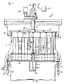
- FIGURE 1 illustrates a diffusion washer which is used for washing paper pulp, and effects backflushing of the screens to keep them unclogged.
- This apparatus indicated generally by reference numeral 10, includes a generally upright vessel 11 having a pulp inlet 12 and a pulp outlet 13 which are vertically spaced from each other. The pulp is introduced into the pulp inlet 12, which typically is at the bottom, and flows vertically within the vessel 11, being discharged through the conduit 13 adjacent the top.
- the basic operative components of the device 10 comprise a plurality of concentric cylindrical screens 14, having screen faces 15 which are generally vertical and are in contact with the pulp.
- the concentric screens 14 are supported on support conduits 16, which typically are in the shape of arms extending radially outwardly from a central hub section 17.
- the conduits 16 are hollow, and the interior may be divided into chambers if desirable. Header openings 19 interior of the arms 16 distribute backflushing fluid.
- the screen arms 16 are mounted for reciprocation in the vertical directions by a reciprocating power structure or structures, preferably three or more hydraulic cylinders 18 which are equally spaced around the periphery of the device 10.
- the cylinders 18 reciprocate the screens 14 and support arms 16 so that they move very slowly in the direction of pulp movement (arrows A in FIGURE 1) until the end of the vertical stroke is reached, and then reverse and move opposite to the direction A. While the relative speeds in direction A and opposite to direction A can be varied, in many installations the movement in direction A is much slower than the movement in the direction opposite to A (i.e. downwardly in the exemplary embodiment illustrated). This serves to assist in keeping the screens 14 relatively clog-free.
- the scrapers 33 are mounted to the rotating arms 30 at the top of the vessel 11 for scraping treatment fluid into the pulp outlet 13 from adjacent the top of the vessel 11.
- the scrapers 33 are powered by the rotation of the arms 30 by the hollow shaft 32.
- Shaft 32 is rotated while supplying wash or bleaching liquid, or the like, by a motor 29.
- the backflushing device for the apparatus 10 is preferably as illustrated in US-A-4,793,161. It includes a simple cylinder 42 which is connected to the bottom of the arms 16 at the central hub 17 thereof, and is open at both ends. The first end is open to the interior of the arms 16, and the second end is open to the volume of the pulp within the vessel 11. Mounted within the cylinder 42 for relative reciprocation with respect to the cylinder is a piston 46. Means are provided for effecting relative movement between the piston 46 and the cylinder 42, which means includes the piston rod 47 connected to the piston 46.
- a second piston and cylinder assembly namely a hydraulic cylinder 54, mounted internally of the vessel 11 and preferably to the arms 16 at the central hub section 17 thereof extending upwardly from the top of the arms 16 while the cylinder 42 extends downwardly from the bottom thereof and the piston rod 47 extends through the conduit arms 16.
- Hydraulic fluid is provided to the hydraulic cylinder 54 by hydraulic fluid lines passing through the top of the vessel 11 through a split pack box 55 connected to the bottom of the hollow shaft 32, and through the sealing conduit 56.
- three hydraulic fluid lines which are typical flexible high pressure oil hoses, 57, 58, and 59, are provided.
- the sealing conduit 56 preferably includes a rigid portion at the split pack box 55, which extends upwardly past the top of the vessel 11. This thus provides an indication (either visual, if transparent or windowed, or sensed by a conventional sensor) of when hydraulic fluid leaks, so that the leak can be detected before the oil has a chance to leak past the sealing conduit 56 into the pulp.
- the hydraulic lines 57, 58 and 59 and the sealing conduit 56 pass through the center of hollow shaft 32 and are sealed thereto by the split pack box 55.
- the hydraulic lines are connected to a top ring 60 at the top of the hydraulic cylinder 54, the conduit 57 leading through opening 61 to the interior of the hydraulic cylinder 54 at one end thereof, while the line 62 -- connected to the line 58 from the ring 60 -- extends to the opposite end of the hydraulic cylinder 54.
- a bottom ring 64 is provided at the bottom of the hydraulic cylinder 54, and a hydraulic line 65 leads from the line 59 to the oil seal 66.
- the hydraulic cylinder 54 includes an actual cylinder 69 which has a piston 70 therein, with a first face 71 selectively exposed to the high pressure from line 57, and a second face 72 selectively exposed to the high pressure from line 58.
- the hydraulic cylinder 54 is preferably mounted to the top of the arms 16 at the hub 17 by a pedestal bracket 75.
- the bracket 75 has openings 76 that allow the flow of pulp therethrough.
- a seal 77 which seals the piston rod 47 so that there is not a significant amount of leakage from the interior of the vessel to the interior of the arms 16, and vice-versa.
- Part of the sealing conduit 56 preferably comprises the flexible bellows 80.
- the bellows 80 may be attached to the ring 60 and the bottom of the rigid portion of the sealing conduit 56, as illustrated most clearly in FIGURE 2.
- the flexible bellows 80 allows tilting movement between the arms 16 and the top of the vessel without interfering with actuation of the backflushing cylinder.
- the flexible hoses 82 extend from the interior of the conduit 56 to a conventional hydraulic unit 83.
- the hydraulic unit provides selective application of hydraulic fluid to lines 57 and 58 to provide for reciprocation of the piston 70 in either direction desired.
- an internal actuator (54) for the backflushing cylinder 46 is provided, with a flexible mount (80) between the top of the vessel and the actuating cylinder.
- the actuator is not seen, there will be no sag or adverse effect on backflushing due to tilting of component parts, and there is no surge in the vessel.
Landscapes
- Life Sciences & Earth Sciences (AREA)
- Engineering & Computer Science (AREA)
- Wood Science & Technology (AREA)
- Paper (AREA)
- Actuator (AREA)
- Reciprocating Pumps (AREA)
- Sealing Devices (AREA)
- Aeration Devices For Treatment Of Activated Polluted Sludge (AREA)
- Structures Of Non-Positive Displacement Pumps (AREA)
- Filtration Of Liquid (AREA)
Abstract
Description
- A pulp treating vessel, such as a diffuser or a thickener, is shown in US-A-4,793,161 and US-A-4,881,286, which effectively backflushes screens within the vessel in an efficient manner to unclog the screens, without surge in the vessel volume. While the structure illustrated in said patents effectively performs the desired function, there are several possible minor drawbacks associated therewith. For example, the extraction arms may sag slightly due to the provision of an external actuator for the internal backflushing cylinder, and operation of the backflushing cylinder can be adversely affected if there is a tilting action between the internal screens and the top of the vessel.
- According to the present invention, the potential minor problems discussed above are eliminated in a simple and effective manner that allows all the desirable results achieved by the structures of said US-A-4,793,161 and US-A-4,881,286 to be accomplished.
- The pulp treating apparatus according to the invention comprises the conventional elements, in common with the structures illustrated in said patents, of a vessel, pulp inlet, pulp outlet, screen and supporting liquid conduits, extraction means, and an internal screen backflushing piston and cylinder. The invention differs from the prior constructions by providing the means for effecting actuation of the backflushing piston within the vessel. Preferably the actuator means comprises a second cylinder mounted on top of the arms that define the supporting liquid conduits for the screens, at a hub section thereof. The backflushing cylinder is mounted to the bottom of the arms at the hub, and a piston rod extends between the pistons associated with the cylinders. Hydraulic fluid is supplied to the actuating cylinder by fluid lines extending from the exterior of the vessel through a sealing conduit. The sealing conduit extends to a position above the top of the vessel so that should there be any hydraulic fluid leakage into the sealing conduit it will be indicated exteriorly of the vessel. A flexible bellows comprises part of the sealing conduit, preferably that portion attached directly to the hydraulic cylinder, to allow tilting action of the arms with respect to the top of the vessel.
- The vessel is particularly adapted for pulp thickening, diffusion washing, and displacement bleaching, but may be utilized in other treatment systems which utilize screens that must be backflushed.
- It is the primary object of the present invention to provide for efficient, reliable, and effective long term backflushing of screens in a pulp treatment vessel. This and other objects of the invention will become clear from an inspection of the detailed description of the invention and from the appended claims.
- The objects of the invention are attained by an apparatus in accordance with claim 1.
-
- FIGURE 1 is a side view, partly in cross-section and partly in elevation, of an exemplary diffusion washer according to the present invention; and
- FIGURE 2 is a detail cross-sectional view showing the hydraulic actuator, and related components, of the apparatus of FIGURE 1.
- FIGURE 1 illustrates a diffusion washer which is used for washing paper pulp, and effects backflushing of the screens to keep them unclogged. This apparatus, indicated generally by reference numeral 10, includes a generally upright vessel 11 having a pulp inlet 12 and a pulp outlet 13 which are vertically spaced from each other. The pulp is introduced into the pulp inlet 12, which typically is at the bottom, and flows vertically within the vessel 11, being discharged through the conduit 13 adjacent the top. The basic operative components of the device 10 comprise a plurality of concentric
cylindrical screens 14, having screen faces 15 which are generally vertical and are in contact with the pulp. Theconcentric screens 14 are supported onsupport conduits 16, which typically are in the shape of arms extending radially outwardly from acentral hub section 17. Theconduits 16 are hollow, and the interior may be divided into chambers if desirable.Header openings 19 interior of thearms 16 distribute backflushing fluid. - The
screen arms 16 are mounted for reciprocation in the vertical directions by a reciprocating power structure or structures, preferably three or morehydraulic cylinders 18 which are equally spaced around the periphery of the device 10. Thecylinders 18 reciprocate thescreens 14 and supportarms 16 so that they move very slowly in the direction of pulp movement (arrows A in FIGURE 1) until the end of the vertical stroke is reached, and then reverse and move opposite to the direction A. While the relative speeds in direction A and opposite to direction A can be varied, in many installations the movement in direction A is much slower than the movement in the direction opposite to A (i.e. downwardly in the exemplary embodiment illustrated). This serves to assist in keeping thescreens 14 relatively clog-free. - What has just been described above is utilizable for thickening operations. Where the pulp is to be treated with a liquid, too, such as a wash liquid or a bleaching liquid, then the rotating
arms 30 with dependingvertical spray nozzles 31 andscrapers 33 are utilized, thearms 30 being provided with treatment liquid through thehollow shaft 32. - The
scrapers 33 are mounted to the rotatingarms 30 at the top of the vessel 11 for scraping treatment fluid into the pulp outlet 13 from adjacent the top of the vessel 11. Thescrapers 33 are powered by the rotation of thearms 30 by thehollow shaft 32. Shaft 32 is rotated while supplying wash or bleaching liquid, or the like, by amotor 29. - The backflushing device for the apparatus 10 is preferably as illustrated in US-A-4,793,161. It includes a
simple cylinder 42 which is connected to the bottom of thearms 16 at thecentral hub 17 thereof, and is open at both ends. The first end is open to the interior of thearms 16, and the second end is open to the volume of the pulp within the vessel 11. Mounted within thecylinder 42 for relative reciprocation with respect to the cylinder is a piston 46. Means are provided for effecting relative movement between the piston 46 and thecylinder 42, which means includes thepiston rod 47 connected to the piston 46. Reciprocation of thepiston rod 47 is provided by a second piston and cylinder assembly, namely a hydraulic cylinder 54, mounted internally of the vessel 11 and preferably to thearms 16 at thecentral hub section 17 thereof extending upwardly from the top of thearms 16 while thecylinder 42 extends downwardly from the bottom thereof and thepiston rod 47 extends through theconduit arms 16. - Hydraulic fluid is provided to the hydraulic cylinder 54 by hydraulic fluid lines passing through the top of the vessel 11 through a
split pack box 55 connected to the bottom of thehollow shaft 32, and through the sealingconduit 56. Preferably three hydraulic fluid lines, which are typical flexible high pressure oil hoses, 57, 58, and 59, are provided. The sealingconduit 56 preferably includes a rigid portion at thesplit pack box 55, which extends upwardly past the top of the vessel 11. This thus provides an indication (either visual, if transparent or windowed, or sensed by a conventional sensor) of when hydraulic fluid leaks, so that the leak can be detected before the oil has a chance to leak past the sealingconduit 56 into the pulp. Thehydraulic lines conduit 56 pass through the center ofhollow shaft 32 and are sealed thereto by thesplit pack box 55. - The hydraulic lines are connected to a
top ring 60 at the top of the hydraulic cylinder 54, the conduit 57 leading through opening 61 to the interior of the hydraulic cylinder 54 at one end thereof, while theline 62 -- connected to theline 58 from thering 60 -- extends to the opposite end of the hydraulic cylinder 54. Abottom ring 64 is provided at the bottom of the hydraulic cylinder 54, and ahydraulic line 65 leads from theline 59 to the oil seal 66. - The hydraulic cylinder 54 includes an
actual cylinder 69 which has apiston 70 therein, with afirst face 71 selectively exposed to the high pressure from line 57, and a second face 72 selectively exposed to the high pressure fromline 58. - The hydraulic cylinder 54 is preferably mounted to the top of the
arms 16 at thehub 17 by apedestal bracket 75. Thebracket 75 has openings 76 that allow the flow of pulp therethrough. Within thepedestal bracket 75 is aseal 77 which seals thepiston rod 47 so that there is not a significant amount of leakage from the interior of the vessel to the interior of thearms 16, and vice-versa. - Part of the sealing
conduit 56 preferably comprises theflexible bellows 80. For example thebellows 80 may be attached to thering 60 and the bottom of the rigid portion of the sealingconduit 56, as illustrated most clearly in FIGURE 2. Theflexible bellows 80 allows tilting movement between thearms 16 and the top of the vessel without interfering with actuation of the backflushing cylinder. - At the top of the vessel 11 the
flexible hoses 82 extend from the interior of theconduit 56 to a conventionalhydraulic unit 83. The hydraulic unit provides selective application of hydraulic fluid tolines 57 and 58 to provide for reciprocation of thepiston 70 in either direction desired. - It will thus be seen that according to the present invention an internal actuator (54) for the backflushing cylinder 46 is provided, with a flexible mount (80) between the top of the vessel and the actuating cylinder. The actuator is not seen, there will be no sag or adverse effect on backflushing due to tilting of component parts, and there is no surge in the vessel.
Claims (14)
- A pulp treating apparatus comprising: a generally upright vessel (11) defining an interior volume for containing pulp to be treated; a pulp inlet (12) to the vessel (11); a pulp outlet (13) from the vessel (11), the pulp flowing generally vertically between the inlet (12) and the outlet (13); a plurality of screens (14) mounted within the vessel (11) and connected to supporting liquid conduits (16); extraction means for withdrawing liquid from the pulp, through the screens (14), and through the conduits (16) to a point outside the vessel (11); screen backflushing means mounted within the vessel (11) and including a first, open-ended, cylinder (42) having first and second ends, the first end in open communication with liquid in the liquid conduits (16), and the second end in open communication with the pulp within the interior volume of the vessel (11); a first piston (46) mounted within the first cylinder (42); and means for effecting relative movement between said first piston (46) and first cylinder (42) to cause the first piston (46) to force liquid out of the first cylinder (42) in one direction of relative movement therebetween, to effect backflushing, and to take liquid into the cylinder (42) in another direction of relative movement therebetween; and said means for effecting relative movement between said first piston (46) and said cylinder (42) comprising a piston rod (47) having first and second ends, and attached at the first end thereof to said first piston (46), characterized in that said piston rod (47) is attached at the second end thereof to a second piston (70); said second piston (70) disposed within a second cylinder (54); and means for supplying high pressure actuating fluid to said second cylinder (54) for powering actuation of said second piston (70); and second piston (70) and second cylinder (54) and piston rod (47) mounted completely within said vessel (11).
- Apparatus as recited in claim 1 wherein said means for supplying actuating fluid to said second cylinder (54) comprises flexible hydraulic fluid lines (57, 58, 59) extending from exteriorly of said vessel (11) to said second cylinder (54); and a sealing conduit (56) disposed around said hydraulic lines (57, 58, 59) to prevent leakage into the pulp should there be a break in a hydraulic line (57, 58, 59).
- Apparatus as recited in claim 2 wherein said sealing conduit (56) comprises indicator means extending exteriorly of said vessel (11) from the interior thereof, to indicate if there has been leakage of hydraulic fluid.
- Apparatus as recited in claim 3 furhter comprising a flexible bellows (80) forming part of said sealing conduit (56) so as to allow tilting action between said sealing conduit (56) and internal components of the vessel (11) connected to said second cylinder (54).
- Apparatus as recited in claim 4 wherein said supporting liquid conduits comprise a plurality of radially extending arms (16), extending outwardly from a central hub (17); and wherein said second cylinder (54) is mounted directly on top of said arms (16) at said hub (17) and said first cylinder (42) is mounted to said arms (16) extending downwardly from said hub (17), with said piston rod (47) passing through the center of said hub (17).
- Apparatus as recited in claim 5 wherein said second cylinder (54) is mounted to said hub (17) by a pedestal (75) which allows the circulation of pulp therethrough past said piston rod (47); and further comprising sealing means (77) surrounding said piston rod (47) at the top of said hub (17).
- Apparatus as recited in claim 2 or 5 further comprising a scraper (33) mounted at the top of said vessel (11) for scraping treatment fluid into said pulp outlet (13) from adjacent the top of said vessel (11), said scraper (33) powered by rotation of a scraper shaft (32); and wherein said scraper shaft (32) is hollow and is disposed in the center of said vessel (11), and wherein said hydraulic lines (57, 58, 59) and sealing conduit (56) pass through the center of said hollow shaft (32) and are sealed thereto by a split pack box (55).
- Apparatus as recited in claim 1 further comprising means (18) for effecting vertical movement of said screens (14) and supporting conduits (16) in the direction of pulp movement at a first speed, and in the direction opposite to pulp movement at a second speed much faster than said first speed.
- Apparatus as recited in claim 1 wherein said extraction means comprises a plurality of radially extending arms (16); extending outwardly from a central hub (17); and wherein said second cylinder (54) is mounted directly on top of said arms (16) at said hub (17) and said first cylinder (42) is mounted to said arms (16) extending downwardly from said hub (17), with said piston rod (47) passing through the center of said hub (17).
- Apparatus as recited in claim 9 further comprising a flexible bellows (80) attached to said second cylinder (54) and extending upwardly therefrom.
- Apparatus as recited in claim 9 comprising a diffusion washer, and including moving spray tubes (31) for introducing wash liquid between said screens (14).
- Apparatus as recited in claim 9 comprising a displacement bleacher, and including spray tubes (31) for introducing bleaching fluid between said screens (14).
- Apparatus as recited in claim 1 comprising a diffusion washer, and including moving spray tubes (31) for introducing wash liquid between said screens (14).
- Apparatus as recited in claim 1 comprising a displacement bleacher, and including spray tubes (31) for introducing bleaching fluid between said screens (14).
Applications Claiming Priority (2)
| Application Number | Priority Date | Filing Date | Title |
|---|---|---|---|
| US07/488,722 US5027620A (en) | 1990-02-26 | 1990-02-26 | Diffuser with flexible bellows and internal actuator |
| US488722 | 1990-02-26 |
Publications (2)
| Publication Number | Publication Date |
|---|---|
| EP0444985A1 EP0444985A1 (en) | 1991-09-04 |
| EP0444985B1 true EP0444985B1 (en) | 1994-08-31 |
Family
ID=23940837
Family Applications (1)
| Application Number | Title | Priority Date | Filing Date |
|---|---|---|---|
| EP91400279A Expired - Lifetime EP0444985B1 (en) | 1990-02-26 | 1991-02-06 | Double diffuser with flexible bellows and internal actuator |
Country Status (9)
| Country | Link |
|---|---|
| US (1) | US5027620A (en) |
| EP (1) | EP0444985B1 (en) |
| JP (1) | JPH0544186A (en) |
| AT (1) | ATE110806T1 (en) |
| BR (1) | BR9100748A (en) |
| CA (1) | CA2036694A1 (en) |
| DE (1) | DE69103649D1 (en) |
| FI (1) | FI910890A7 (en) |
| NO (1) | NO910742L (en) |
Families Citing this family (6)
| Publication number | Priority date | Publication date | Assignee | Title |
|---|---|---|---|---|
| SE469079B (en) * | 1992-03-17 | 1993-05-10 | Kamyr Ab | SILAN SYSTEM WITH BACKWIND ORGAN |
| SE501863C2 (en) * | 1993-09-22 | 1995-06-06 | Kvaerner Pulping Tech | Apparatus for distributing washing liquid for washing pulp |
| SE502064C2 (en) * | 1993-11-29 | 1995-07-31 | Kvaerner Pulping Tech | Method and apparatus for dispensing fiber pulp |
| SE503071C2 (en) * | 1994-07-04 | 1996-03-18 | Kvaerner Pulping Tech | Continuous pulp wash diffuser including annular hydraulic cylinders |
| US6272710B1 (en) | 1998-05-07 | 2001-08-14 | James R. Prough | Plate diffuser for treating comminuted cellulosic fibrous material |
| CA2550911A1 (en) * | 2006-06-23 | 2007-12-23 | Larry J. Chernoff | Distributor for domestic water filters |
Family Cites Families (11)
| Publication number | Priority date | Publication date | Assignee | Title |
|---|---|---|---|---|
| SE324950C (en) * | 1967-04-13 | 1977-02-28 | Sunds Ab | PROCEDURE AND DEVICE FOR LIQUID TREATMENT PREFERREDLY WASHING OF FIBER SUSPENSIONS OF CELLULOSA MASS |
| SE394821B (en) * | 1975-04-15 | 1977-07-11 | Kamyr Ab | METHOD AND DEVICE FOR DRAINING MOVEMENT SUSPENSIONS |
| US4375410A (en) * | 1979-04-25 | 1983-03-01 | Kamyr Ab | Reciprocating diffuser arrangements in an elongated vessel |
| US4556494A (en) * | 1980-12-04 | 1985-12-03 | Kamyr Aktiebolag | Method of diffusion washing or thickening of pulp |
| SE451672B (en) * | 1982-03-08 | 1987-10-26 | Svenskt Mjoelksocker Ab | filtering device |
| US4441224A (en) * | 1982-05-04 | 1984-04-10 | Laakso Oliver A | Method of continuously treating a fibrous suspension |
| US4521315A (en) * | 1984-01-24 | 1985-06-04 | Laakso Oliver A | Pulp thickening utilizing stationary screens |
| GB2159725B (en) * | 1984-06-09 | 1988-06-02 | Klimatank Holdings Limited | Filter apparatus |
| US4881286A (en) * | 1987-11-27 | 1989-11-21 | Kamyr Ab | Effective diffuser/thickener screen backflushing |
| US4793161A (en) * | 1987-11-27 | 1988-12-27 | Kamyr Ab | Effective diffuser/thickener screen backflushing |
| US4971694A (en) * | 1989-01-05 | 1990-11-20 | Kamyr Ab | Double diffuser with backflush pistons |
-
1990
- 1990-02-26 US US07/488,722 patent/US5027620A/en not_active Expired - Fee Related
-
1991
- 1991-02-06 AT AT91400279T patent/ATE110806T1/en not_active IP Right Cessation
- 1991-02-06 DE DE69103649T patent/DE69103649D1/en not_active Expired - Lifetime
- 1991-02-06 EP EP91400279A patent/EP0444985B1/en not_active Expired - Lifetime
- 1991-02-20 CA CA002036694A patent/CA2036694A1/en not_active Abandoned
- 1991-02-25 BR BR919100748A patent/BR9100748A/en not_active Application Discontinuation
- 1991-02-25 FI FI910890A patent/FI910890A7/en not_active Application Discontinuation
- 1991-02-25 JP JP3030062A patent/JPH0544186A/en active Pending
- 1991-02-25 NO NO91910742A patent/NO910742L/en unknown
Also Published As
| Publication number | Publication date |
|---|---|
| BR9100748A (en) | 1991-10-29 |
| NO910742L (en) | 1991-08-27 |
| JPH0544186A (en) | 1993-02-23 |
| ATE110806T1 (en) | 1994-09-15 |
| US5027620A (en) | 1991-07-02 |
| FI910890A0 (en) | 1991-02-25 |
| NO910742D0 (en) | 1991-02-25 |
| FI910890A7 (en) | 1991-08-27 |
| DE69103649D1 (en) | 1994-10-06 |
| CA2036694A1 (en) | 1991-08-27 |
| EP0444985A1 (en) | 1991-09-04 |
Similar Documents
| Publication | Publication Date | Title |
|---|---|---|
| CA1317552C (en) | Effective diffuser/thickener screen backflushing | |
| US3772144A (en) | Apparatus and method for thickening and washing suspensions containing fibrous material | |
| EP0444985B1 (en) | Double diffuser with flexible bellows and internal actuator | |
| US3027011A (en) | Pulp washer and filter | |
| CA1313967C (en) | Double diffuser with backflush pistons | |
| US4881286A (en) | Effective diffuser/thickener screen backflushing | |
| EP0337432A2 (en) | Method and apparatus for treating fiber suspensions | |
| US4529482A (en) | Apparatus for the treatment of pulp having oscillating distributing wiper blades | |
| FI93750C (en) | Device for dewatering the pulp | |
| US5858228A (en) | Separation filter with turbine generating controlled turbulence for solids suspended in liquid | |
| EP0056859B1 (en) | Diffuser arrangements | |
| US4375410A (en) | Reciprocating diffuser arrangements in an elongated vessel | |
| FI72051C (en) | FOERTJOCKNINGSANORDNING. | |
| US4394267A (en) | Diffuser assembly | |
| SE444469B (en) | DEVICE FOR SYNCHRONIZED HYDRAULIC FLUID SUPPLY OF TWO OR MULTIPLE HYDRAULIC ENGINES | |
| CN213855131U (en) | Centrifuge capable of distributing materials uniformly | |
| RU2215905C2 (en) | Vertical pump | |
| US5770072A (en) | Multiple inlet valve with means to isolate each inlet individually and direct a reverse flow therethrough | |
| SU1475740A1 (en) | Arrangement for washing containers | |
| CA2005848A1 (en) | Centrifugal washer for paper pulp | |
| SU556210A1 (en) | Apparatus for washing and thickening the fibrous suspension | |
| SU1402318A1 (en) | Sprayer | |
| SU856596A1 (en) | Unit for cleaning parts | |
| SU1673916A1 (en) | Method and apparatus for local loading of article surface | |
| RU1831594C (en) | Pump |
Legal Events
| Date | Code | Title | Description |
|---|---|---|---|
| PUAI | Public reference made under article 153(3) epc to a published international application that has entered the european phase |
Free format text: ORIGINAL CODE: 0009012 |
|
| AK | Designated contracting states |
Kind code of ref document: A1 Designated state(s): AT DE FR SE |
|
| 17P | Request for examination filed |
Effective date: 19911011 |
|
| 17Q | First examination report despatched |
Effective date: 19930618 |
|
| GRAA | (expected) grant |
Free format text: ORIGINAL CODE: 0009210 |
|
| AK | Designated contracting states |
Kind code of ref document: B1 Designated state(s): AT DE FR SE |
|
| PG25 | Lapsed in a contracting state [announced via postgrant information from national office to epo] |
Ref country code: FR Effective date: 19940831 Ref country code: AT Effective date: 19940831 |
|
| REF | Corresponds to: |
Ref document number: 110806 Country of ref document: AT Date of ref document: 19940915 Kind code of ref document: T |
|
| REF | Corresponds to: |
Ref document number: 69103649 Country of ref document: DE Date of ref document: 19941006 |
|
| PG25 | Lapsed in a contracting state [announced via postgrant information from national office to epo] |
Ref country code: DE Effective date: 19941201 |
|
| EN | Fr: translation not filed | ||
| EAL | Se: european patent in force in sweden |
Ref document number: 91400279.5 |
|
| PGFP | Annual fee paid to national office [announced via postgrant information from national office to epo] |
Ref country code: SE Payment date: 19950213 Year of fee payment: 5 |
|
| PLBE | No opposition filed within time limit |
Free format text: ORIGINAL CODE: 0009261 |
|
| STAA | Information on the status of an ep patent application or granted ep patent |
Free format text: STATUS: NO OPPOSITION FILED WITHIN TIME LIMIT |
|
| 26N | No opposition filed | ||
| PG25 | Lapsed in a contracting state [announced via postgrant information from national office to epo] |
Ref country code: SE Effective date: 19960207 |