EP0444985B1 - Diffuseur double avec soufflets souples et vérin pneumatique interieur - Google Patents
Diffuseur double avec soufflets souples et vérin pneumatique interieur Download PDFInfo
- Publication number
- EP0444985B1 EP0444985B1 EP91400279A EP91400279A EP0444985B1 EP 0444985 B1 EP0444985 B1 EP 0444985B1 EP 91400279 A EP91400279 A EP 91400279A EP 91400279 A EP91400279 A EP 91400279A EP 0444985 B1 EP0444985 B1 EP 0444985B1
- Authority
- EP
- European Patent Office
- Prior art keywords
- cylinder
- vessel
- pulp
- recited
- piston
- Prior art date
- Legal status (The legal status is an assumption and is not a legal conclusion. Google has not performed a legal analysis and makes no representation as to the accuracy of the status listed.)
- Expired - Lifetime
Links
- 238000007789 sealing Methods 0.000 claims abstract description 19
- 239000012530 fluid Substances 0.000 claims abstract description 18
- 239000007788 liquid Substances 0.000 claims description 16
- 238000004061 bleaching Methods 0.000 claims description 5
- 238000009792 diffusion process Methods 0.000 claims description 5
- 239000007921 spray Substances 0.000 claims description 5
- 238000000605 extraction Methods 0.000 claims description 4
- NJPPVKZQTLUDBO-UHFFFAOYSA-N novaluron Chemical compound C1=C(Cl)C(OC(F)(F)C(OC(F)(F)F)F)=CC=C1NC(=O)NC(=O)C1=C(F)C=CC=C1F NJPPVKZQTLUDBO-UHFFFAOYSA-N 0.000 claims description 4
- 238000006073 displacement reaction Methods 0.000 claims description 3
- 230000000694 effects Effects 0.000 claims description 3
- 238000007790 scraping Methods 0.000 claims description 2
- 229920001131 Pulp (paper) Polymers 0.000 abstract description 2
- 239000002562 thickening agent Substances 0.000 abstract description 2
- 230000002411 adverse Effects 0.000 description 2
- 230000008719 thickening Effects 0.000 description 2
- 238000005406 washing Methods 0.000 description 2
- 238000010276 construction Methods 0.000 description 1
- 238000007689 inspection Methods 0.000 description 1
- 238000009434 installation Methods 0.000 description 1
- 230000002452 interceptive effect Effects 0.000 description 1
- 230000007774 longterm Effects 0.000 description 1
- 230000000007 visual effect Effects 0.000 description 1
Images

Classifications
-
- D—TEXTILES; PAPER
- D21—PAPER-MAKING; PRODUCTION OF CELLULOSE
- D21C—PRODUCTION OF CELLULOSE BY REMOVING NON-CELLULOSE SUBSTANCES FROM CELLULOSE-CONTAINING MATERIALS; REGENERATION OF PULPING LIQUORS; APPARATUS THEREFOR
- D21C9/00—After-treatment of cellulose pulp, e.g. of wood pulp, or cotton linters ; Treatment of dilute or dewatered pulp or process improvement taking place after obtaining the raw cellulosic material and not provided for elsewhere
- D21C9/02—Washing ; Displacing cooking or pulp-treating liquors contained in the pulp by fluids, e.g. wash water or other pulp-treating agents
- D21C9/04—Washing ; Displacing cooking or pulp-treating liquors contained in the pulp by fluids, e.g. wash water or other pulp-treating agents in diffusers ; Washing of pulp of fluid consistency without substantially thickening
Definitions
- a pulp treating vessel such as a diffuser or a thickener
- US-A-4,793,161 and US-A-4,881,286, which effectively backflushes screens within the vessel in an efficient manner to unclog the screens, without surge in the vessel volume.
- the structure illustrated in said patents effectively performs the desired function, there are several possible minor drawbacks associated therewith.
- the extraction arms may sag slightly due to the provision of an external actuator for the internal backflushing cylinder, and operation of the backflushing cylinder can be adversely affected if there is a tilting action between the internal screens and the top of the vessel.
- the pulp treating apparatus comprises the conventional elements, in common with the structures illustrated in said patents, of a vessel, pulp inlet, pulp outlet, screen and supporting liquid conduits, extraction means, and an internal screen backflushing piston and cylinder.
- the invention differs from the prior constructions by providing the means for effecting actuation of the backflushing piston within the vessel.
- the actuator means comprises a second cylinder mounted on top of the arms that define the supporting liquid conduits for the screens, at a hub section thereof.
- the backflushing cylinder is mounted to the bottom of the arms at the hub, and a piston rod extends between the pistons associated with the cylinders. Hydraulic fluid is supplied to the actuating cylinder by fluid lines extending from the exterior of the vessel through a sealing conduit.
- the sealing conduit extends to a position above the top of the vessel so that should there be any hydraulic fluid leakage into the sealing conduit it will be indicated exteriorly of the vessel.
- a flexible bellows comprises part of the sealing conduit, preferably that portion attached directly to the hydraulic cylinder, to allow tilting action of the arms with respect to the top of the vessel.
- the vessel is particularly adapted for pulp thickening, diffusion washing, and displacement bleaching, but may be utilized in other treatment systems which utilize screens that must be backflushed.
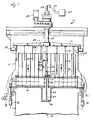
- FIGURE 1 illustrates a diffusion washer which is used for washing paper pulp, and effects backflushing of the screens to keep them unclogged.
- This apparatus indicated generally by reference numeral 10, includes a generally upright vessel 11 having a pulp inlet 12 and a pulp outlet 13 which are vertically spaced from each other. The pulp is introduced into the pulp inlet 12, which typically is at the bottom, and flows vertically within the vessel 11, being discharged through the conduit 13 adjacent the top.
- the basic operative components of the device 10 comprise a plurality of concentric cylindrical screens 14, having screen faces 15 which are generally vertical and are in contact with the pulp.
- the concentric screens 14 are supported on support conduits 16, which typically are in the shape of arms extending radially outwardly from a central hub section 17.
- the conduits 16 are hollow, and the interior may be divided into chambers if desirable. Header openings 19 interior of the arms 16 distribute backflushing fluid.
- the screen arms 16 are mounted for reciprocation in the vertical directions by a reciprocating power structure or structures, preferably three or more hydraulic cylinders 18 which are equally spaced around the periphery of the device 10.
- the cylinders 18 reciprocate the screens 14 and support arms 16 so that they move very slowly in the direction of pulp movement (arrows A in FIGURE 1) until the end of the vertical stroke is reached, and then reverse and move opposite to the direction A. While the relative speeds in direction A and opposite to direction A can be varied, in many installations the movement in direction A is much slower than the movement in the direction opposite to A (i.e. downwardly in the exemplary embodiment illustrated). This serves to assist in keeping the screens 14 relatively clog-free.
- the scrapers 33 are mounted to the rotating arms 30 at the top of the vessel 11 for scraping treatment fluid into the pulp outlet 13 from adjacent the top of the vessel 11.
- the scrapers 33 are powered by the rotation of the arms 30 by the hollow shaft 32.
- Shaft 32 is rotated while supplying wash or bleaching liquid, or the like, by a motor 29.
- the backflushing device for the apparatus 10 is preferably as illustrated in US-A-4,793,161. It includes a simple cylinder 42 which is connected to the bottom of the arms 16 at the central hub 17 thereof, and is open at both ends. The first end is open to the interior of the arms 16, and the second end is open to the volume of the pulp within the vessel 11. Mounted within the cylinder 42 for relative reciprocation with respect to the cylinder is a piston 46. Means are provided for effecting relative movement between the piston 46 and the cylinder 42, which means includes the piston rod 47 connected to the piston 46.
- a second piston and cylinder assembly namely a hydraulic cylinder 54, mounted internally of the vessel 11 and preferably to the arms 16 at the central hub section 17 thereof extending upwardly from the top of the arms 16 while the cylinder 42 extends downwardly from the bottom thereof and the piston rod 47 extends through the conduit arms 16.
- Hydraulic fluid is provided to the hydraulic cylinder 54 by hydraulic fluid lines passing through the top of the vessel 11 through a split pack box 55 connected to the bottom of the hollow shaft 32, and through the sealing conduit 56.
- three hydraulic fluid lines which are typical flexible high pressure oil hoses, 57, 58, and 59, are provided.
- the sealing conduit 56 preferably includes a rigid portion at the split pack box 55, which extends upwardly past the top of the vessel 11. This thus provides an indication (either visual, if transparent or windowed, or sensed by a conventional sensor) of when hydraulic fluid leaks, so that the leak can be detected before the oil has a chance to leak past the sealing conduit 56 into the pulp.
- the hydraulic lines 57, 58 and 59 and the sealing conduit 56 pass through the center of hollow shaft 32 and are sealed thereto by the split pack box 55.
- the hydraulic lines are connected to a top ring 60 at the top of the hydraulic cylinder 54, the conduit 57 leading through opening 61 to the interior of the hydraulic cylinder 54 at one end thereof, while the line 62 -- connected to the line 58 from the ring 60 -- extends to the opposite end of the hydraulic cylinder 54.
- a bottom ring 64 is provided at the bottom of the hydraulic cylinder 54, and a hydraulic line 65 leads from the line 59 to the oil seal 66.
- the hydraulic cylinder 54 includes an actual cylinder 69 which has a piston 70 therein, with a first face 71 selectively exposed to the high pressure from line 57, and a second face 72 selectively exposed to the high pressure from line 58.
- the hydraulic cylinder 54 is preferably mounted to the top of the arms 16 at the hub 17 by a pedestal bracket 75.
- the bracket 75 has openings 76 that allow the flow of pulp therethrough.
- a seal 77 which seals the piston rod 47 so that there is not a significant amount of leakage from the interior of the vessel to the interior of the arms 16, and vice-versa.
- Part of the sealing conduit 56 preferably comprises the flexible bellows 80.
- the bellows 80 may be attached to the ring 60 and the bottom of the rigid portion of the sealing conduit 56, as illustrated most clearly in FIGURE 2.
- the flexible bellows 80 allows tilting movement between the arms 16 and the top of the vessel without interfering with actuation of the backflushing cylinder.
- the flexible hoses 82 extend from the interior of the conduit 56 to a conventional hydraulic unit 83.
- the hydraulic unit provides selective application of hydraulic fluid to lines 57 and 58 to provide for reciprocation of the piston 70 in either direction desired.
- an internal actuator (54) for the backflushing cylinder 46 is provided, with a flexible mount (80) between the top of the vessel and the actuating cylinder.
- the actuator is not seen, there will be no sag or adverse effect on backflushing due to tilting of component parts, and there is no surge in the vessel.
Landscapes
- Life Sciences & Earth Sciences (AREA)
- Engineering & Computer Science (AREA)
- Wood Science & Technology (AREA)
- Paper (AREA)
- Actuator (AREA)
- Structures Of Non-Positive Displacement Pumps (AREA)
- Aeration Devices For Treatment Of Activated Polluted Sludge (AREA)
- Filtration Of Liquid (AREA)
- Reciprocating Pumps (AREA)
- Sealing Devices (AREA)
Claims (14)
- Appareil de traitement de pâte à papier, comprenant une cuve (11) dans l'ensemble verticale, délimitant un volume intérieur destiné à contenir la pâte à papier à traiter, une entrée de pâte à papier (12) dans la cuve (11), une sortie de pâte à papier (13) hors de la cuve (11), la pâte s'écoulant d'une manière dans l'ensemble verticale entre l'entrée (12) et la sortie (13), plusieurs tamis (14), montés dans la cuve (11) et fixés à des conduits de liquide (16) de support, des moyens d'extraction, servant à extraire du liquide de la pâte à papier à travers les tamis (14) et à travers les conduits (16) jusqu'à un point situé à l'extérieur de la cuve (11), des moyens de rinçage des tamis, montés dans la cuve (11) et comprenant un premier cylindre (42) à extrémités ouvertes comportant une première et une seconde extrémités, la première extrémité communiquant librement avec le liquide situé dans les conduits de liquide (16) et la seconde extrémité communiquant librement avec la pâte à papier située dans le volume intérieur de la cuve (11), un premier piston (46), monté dans le premier cylindre (42), et des moyens servant à provoquer un mouvement relatif entre le premier piston (46) et le premier cylindre (42) de façon à astreindre le premier piston (46) à expulser du liquide hors du premier cylindre (42) dans un premier sens de déplacement relatif entre ce piston et ce cylindre, à provoquer un rinçage et à prélever du liquide dans le cylindre (42) dans un autre sens de déplacement relatif entre le piston et le cylindre, ces moyens servant à provoquer un déplacement relatif entre le premier piston (46) et le cylindre (42) comprenant une tige de piston (47) qui comporte une première et une seconde extrémités et qui, à sa première extrémité, est fixée au premier piston (46), caractérisé en ce qu'à sa seconde extrémité, la tige de piston (47) est fixée à un second piston (70) et en ce que ce second piston (70) est disposé dans un second cylindre (54), des moyens étant prévus pour envoyer un fluide d'actionnement à pression élevée dans le second cylindre (54) en vue de commander l'actionnement du second piston (70), tandis que le second piston (70), le second cylindre (54) et la tige de piston (47) sont montés complètement à l'intérieur de la cuve (11).
- Appareil selon la revendication 1, dans lequel les moyens servant à envoyer un fluide d'actionnement au second cylindre (54) comprennent des tuyauteries flexibles de fluide hydraulique (57, 58, 59), s'étendant d'un emplacement situé à l'extérieur de la cuve (11) au second cylindre (54), et un conduit d'étanchéité (56) disposé autour des tuyauteries hydrauliques (57, 58, 59) en vue d'empêcher des fuites dans la pâte à papier en cas de rupture se produisant dans une tuyauterie hydraulique (57, 58, 59).
- Appareil selon la revendication 2, dans lequel le conduit d'étanchéité (56) comprend des moyens indicateurs s'étendant d'un emplacement situé à l'extérieur de la cuve (11) jusqu'à l'intérieur de cette dernière, de façon à indiquer s'il s'est produit une fuite de fluide hydraulique.
- Appareil selon la revendication 3, comprenant en outre un soufflet souple (80) faisant partie du conduit d'étanchéité (56), de façon à permettre une action d'inclinaison entre le conduit d'étanchéité (56) et les composants intérieurs de la cuve (11) qui sont reliés au second cylindre (54).
- Appareil selon la revendication 4, dans lequel les conduits de liquide de support comprennent plusieurs bras orientés radialement (16) qui s'étendent vers l'extérieur à partir d'un moyeu central (17) et dans lequel le second cylindre (54) est monté directement sur la partie supérieure des bras (16) à l'endroit du moyeu (17), tandis que le premier cylindre (42) est monté sur les bras (16) en s'étendant vers le bas à partir du moyeu (17), la tige de piston (47) traversant la partie centrale du moyeu (17).
- Appareil selon la revendication 5, dans lequel le second cylindre (54) est monté sur le moyeu (17) au moyen d'un socle (75) qui permet que la pâte à papier circule à travers lui en passant à côté de la tige de piston (47), l'appareil comprenant en outre des moyens d'étanchéité (77) entourant la tige de piston (47) à la partie supérieure du moyeu (17).
- Appareil selon l'une des revendications 2 et 5, comprenant en outre un racleur (33) monté à la partie supérieure de la cuve (11) et servant à racler le fluide de traitement situé dans la sortie de pâte à papier (13) à partir d'un emplacement adjacent à la partie supérieure de la cuve (11), ce racleur (33) étant entraîné par la rotation d'un arbre de racleur (32) et cet arbre de racleur (32) étant creux et disposé dans la partie centrale de la cuve (11), tandis que les tuyauteries hydrauliques (57, 58, 59) et le conduit d'étanchéité (56) traversent la partie centrale de l'arbre creux (32) et sont montés d'une manière étanche vis-à-vis de cet arbre creux au moyen d'un presse-étoupe (55) en deux parties.
- Appareil selon la revendication 1, comprenant en outre des moyens (18) servant à provoquer un déplacement vertical des tamis (14) et des conduits de support (16) dans le sens de déplacement de la pâte à papier à une première vitesse et dans le sens opposé au déplacement de la pâte à papier à une seconde vitesse beaucoup plus grande que la première vitesse.
- Appareil selon la revendication 1, dans lequel les moyens d'extraction comprennent plusieurs bras orientés radialement (16) qui s'étendent vers l'extérieur à partir d'un moyeu central (17) et dans lequel le second cylindre (54) est monté directement sur la partie supérieure des bras (16) à l'endroit du moyeu (17), tandis que le premier cylindre (42) est monté sur les bras (16) en s'étendant vers le bas à partir du moyeu (17), la tige de piston (47) traversant la partie centrale du moyeu (17).
- Appareil selon la revendication 9, comprenant en outre un soufflet souple (80) fixé au second cylindre( 54) et s'étendant vers le haut à partir de ce second cylindre.
- Appareil selon la revendication 9, comprenant un dispositif de lavage par diffusion et comportant des tubes mobiles de pulvérisation (31) servant à introduire un liquide de lavage entre les tamis (14).
- Appareil selon la revendication 9, comprenant un dispositif de blanchiment à déplacement et comportant des tubes de pulvérisation (31) servant à introduire un fluide de blanchiment entre les tamis (14).
- Appareil selon la revendication 1, comprenant un dispositif de lavage à diffusion et comportant des tubes mobiles de pulvérisation (31) servant à introduire un liquide de lavage entre les tamis (14).
- Appareil selon la revendication 1, comprenant un dispositif de blanchiment à déplacement et comportant des tubes de pulvérisation (31) servant à introduire un fluide de blanchiment entre les tamis (14).
Applications Claiming Priority (2)
| Application Number | Priority Date | Filing Date | Title |
|---|---|---|---|
| US07/488,722 US5027620A (en) | 1990-02-26 | 1990-02-26 | Diffuser with flexible bellows and internal actuator |
| US488722 | 1990-02-26 |
Publications (2)
| Publication Number | Publication Date |
|---|---|
| EP0444985A1 EP0444985A1 (fr) | 1991-09-04 |
| EP0444985B1 true EP0444985B1 (fr) | 1994-08-31 |
Family
ID=23940837
Family Applications (1)
| Application Number | Title | Priority Date | Filing Date |
|---|---|---|---|
| EP91400279A Expired - Lifetime EP0444985B1 (fr) | 1990-02-26 | 1991-02-06 | Diffuseur double avec soufflets souples et vérin pneumatique interieur |
Country Status (9)
| Country | Link |
|---|---|
| US (1) | US5027620A (fr) |
| EP (1) | EP0444985B1 (fr) |
| JP (1) | JPH0544186A (fr) |
| AT (1) | ATE110806T1 (fr) |
| BR (1) | BR9100748A (fr) |
| CA (1) | CA2036694A1 (fr) |
| DE (1) | DE69103649D1 (fr) |
| FI (1) | FI910890A7 (fr) |
| NO (1) | NO910742L (fr) |
Families Citing this family (6)
| Publication number | Priority date | Publication date | Assignee | Title |
|---|---|---|---|---|
| SE9200808L (sv) * | 1992-03-17 | 1993-05-10 | Kamyr Ab | Silanordning med backspolningsorgan |
| SE501863C2 (sv) * | 1993-09-22 | 1995-06-06 | Kvaerner Pulping Tech | Anordning för fördelning av tvättvätska för tvättning av pappersmassa |
| SE502064C2 (sv) * | 1993-11-29 | 1995-07-31 | Kvaerner Pulping Tech | Sätt och anordning för utmatning av fibermassa |
| SE503071C2 (sv) * | 1994-07-04 | 1996-03-18 | Kvaerner Pulping Tech | Kontinuerlig diffusör för massatvätt innefattande i ring fördelade hydraulcylindrar |
| SE9901668A0 (en) | 1998-05-07 | 2000-11-07 | J Robert Prough | Plate diffuser for treating comminuted cellulosic fibrous material |
| CA2550911A1 (fr) * | 2006-06-23 | 2007-12-23 | Larry J. Chernoff | Distributeur pour filtres a eau domestiques |
Family Cites Families (11)
| Publication number | Priority date | Publication date | Assignee | Title |
|---|---|---|---|---|
| SE324950C (sv) * | 1967-04-13 | 1977-02-28 | Sunds Ab | Forfarande och anordning for vetskebehandling foretredesvis tvettning av fibersuspensioner av cellulosamassa |
| SE394821B (sv) * | 1975-04-15 | 1977-07-11 | Kamyr Ab | Sett och anordning for avvattning av suspensioner i rorelse |
| US4375410A (en) * | 1979-04-25 | 1983-03-01 | Kamyr Ab | Reciprocating diffuser arrangements in an elongated vessel |
| US4556494A (en) * | 1980-12-04 | 1985-12-03 | Kamyr Aktiebolag | Method of diffusion washing or thickening of pulp |
| SE451672B (sv) * | 1982-03-08 | 1987-10-26 | Svenskt Mjoelksocker Ab | Filtreringsanordning |
| US4441224A (en) * | 1982-05-04 | 1984-04-10 | Laakso Oliver A | Method of continuously treating a fibrous suspension |
| US4521315A (en) * | 1984-01-24 | 1985-06-04 | Laakso Oliver A | Pulp thickening utilizing stationary screens |
| GB2159725B (en) * | 1984-06-09 | 1988-06-02 | Klimatank Holdings Limited | Filter apparatus |
| US4793161A (en) * | 1987-11-27 | 1988-12-27 | Kamyr Ab | Effective diffuser/thickener screen backflushing |
| US4881286A (en) * | 1987-11-27 | 1989-11-21 | Kamyr Ab | Effective diffuser/thickener screen backflushing |
| US4971694A (en) * | 1989-01-05 | 1990-11-20 | Kamyr Ab | Double diffuser with backflush pistons |
-
1990
- 1990-02-26 US US07/488,722 patent/US5027620A/en not_active Expired - Fee Related
-
1991
- 1991-02-06 EP EP91400279A patent/EP0444985B1/fr not_active Expired - Lifetime
- 1991-02-06 DE DE69103649T patent/DE69103649D1/de not_active Expired - Lifetime
- 1991-02-06 AT AT91400279T patent/ATE110806T1/de not_active IP Right Cessation
- 1991-02-20 CA CA002036694A patent/CA2036694A1/fr not_active Abandoned
- 1991-02-25 BR BR919100748A patent/BR9100748A/pt not_active Application Discontinuation
- 1991-02-25 NO NO91910742A patent/NO910742L/no unknown
- 1991-02-25 FI FI910890A patent/FI910890A7/fi not_active Application Discontinuation
- 1991-02-25 JP JP3030062A patent/JPH0544186A/ja active Pending
Also Published As
| Publication number | Publication date |
|---|---|
| DE69103649D1 (de) | 1994-10-06 |
| BR9100748A (pt) | 1991-10-29 |
| JPH0544186A (ja) | 1993-02-23 |
| US5027620A (en) | 1991-07-02 |
| EP0444985A1 (fr) | 1991-09-04 |
| NO910742L (no) | 1991-08-27 |
| FI910890A7 (fi) | 1991-08-27 |
| ATE110806T1 (de) | 1994-09-15 |
| NO910742D0 (no) | 1991-02-25 |
| FI910890A0 (fi) | 1991-02-25 |
| CA2036694A1 (fr) | 1991-08-27 |
Similar Documents
| Publication | Publication Date | Title |
|---|---|---|
| CA1317552C (fr) | Nettoyage du filtre d'un diffuseur/epaississeur par circulation inverse du courant | |
| US3772144A (en) | Apparatus and method for thickening and washing suspensions containing fibrous material | |
| JPS5825909B2 (ja) | 間隙パツキンにおける媒体の漏洩流排出装置 | |
| EP0444985B1 (fr) | Diffuseur double avec soufflets souples et vérin pneumatique interieur | |
| US3027011A (en) | Pulp washer and filter | |
| CA1313967C (fr) | Diffuseur double a pistons de contre-circulation | |
| US4881286A (en) | Effective diffuser/thickener screen backflushing | |
| EP0337432A2 (fr) | Procédé et dispositif de traitement de suspensions fibreuses | |
| US4529482A (en) | Apparatus for the treatment of pulp having oscillating distributing wiper blades | |
| FI93750C (fi) | Laite massan vedenpoistoa varten | |
| US5858228A (en) | Separation filter with turbine generating controlled turbulence for solids suspended in liquid | |
| EP0056859B1 (fr) | Agencements d'un diffuseur | |
| US4375410A (en) | Reciprocating diffuser arrangements in an elongated vessel | |
| FI72051C (fi) | Foertjockningsanordning. | |
| US4394267A (en) | Diffuser assembly | |
| SE444469B (sv) | Anordning for synkroniserad hydraulfluidumforsorjning av tva eller flera hydraulmotorer | |
| CN213855131U (zh) | 一种均匀布料的离心机 | |
| RU2215905C2 (ru) | Вертикальный насос | |
| US5770072A (en) | Multiple inlet valve with means to isolate each inlet individually and direct a reverse flow therethrough | |
| SU1475740A1 (ru) | Устройство дл мойки емкостей | |
| CA2005848A1 (fr) | Laveur centrifuge pour pate a papier | |
| SU556210A1 (ru) | Устройство дл промывки и сгущени волокнистой суспензии | |
| SU1402318A1 (ru) | Опрыскиватель | |
| SU856596A1 (ru) | Установка дл очистки деталей | |
| SU1673916A1 (ru) | Способ местного нагружени поверхности издели и устройство дл его осуществлени |
Legal Events
| Date | Code | Title | Description |
|---|---|---|---|
| PUAI | Public reference made under article 153(3) epc to a published international application that has entered the european phase |
Free format text: ORIGINAL CODE: 0009012 |
|
| AK | Designated contracting states |
Kind code of ref document: A1 Designated state(s): AT DE FR SE |
|
| 17P | Request for examination filed |
Effective date: 19911011 |
|
| 17Q | First examination report despatched |
Effective date: 19930618 |
|
| GRAA | (expected) grant |
Free format text: ORIGINAL CODE: 0009210 |
|
| AK | Designated contracting states |
Kind code of ref document: B1 Designated state(s): AT DE FR SE |
|
| PG25 | Lapsed in a contracting state [announced via postgrant information from national office to epo] |
Ref country code: FR Effective date: 19940831 Ref country code: AT Effective date: 19940831 |
|
| REF | Corresponds to: |
Ref document number: 110806 Country of ref document: AT Date of ref document: 19940915 Kind code of ref document: T |
|
| REF | Corresponds to: |
Ref document number: 69103649 Country of ref document: DE Date of ref document: 19941006 |
|
| PG25 | Lapsed in a contracting state [announced via postgrant information from national office to epo] |
Ref country code: DE Effective date: 19941201 |
|
| EN | Fr: translation not filed | ||
| EAL | Se: european patent in force in sweden |
Ref document number: 91400279.5 |
|
| PGFP | Annual fee paid to national office [announced via postgrant information from national office to epo] |
Ref country code: SE Payment date: 19950213 Year of fee payment: 5 |
|
| PLBE | No opposition filed within time limit |
Free format text: ORIGINAL CODE: 0009261 |
|
| STAA | Information on the status of an ep patent application or granted ep patent |
Free format text: STATUS: NO OPPOSITION FILED WITHIN TIME LIMIT |
|
| 26N | No opposition filed | ||
| PG25 | Lapsed in a contracting state [announced via postgrant information from national office to epo] |
Ref country code: SE Effective date: 19960207 |