EP0444988A1 - Automatische Maschine zum Befestigen von Teilen auf Tür- oder Fensterpfosten - Google Patents
Automatische Maschine zum Befestigen von Teilen auf Tür- oder Fensterpfosten Download PDFInfo
- Publication number
- EP0444988A1 EP0444988A1 EP91400308A EP91400308A EP0444988A1 EP 0444988 A1 EP0444988 A1 EP 0444988A1 EP 91400308 A EP91400308 A EP 91400308A EP 91400308 A EP91400308 A EP 91400308A EP 0444988 A1 EP0444988 A1 EP 0444988A1
- Authority
- EP
- European Patent Office
- Prior art keywords
- unit according
- station
- frame
- components
- bearings
- Prior art date
- Legal status (The legal status is an assumption and is not a legal conclusion. Google has not performed a legal analysis and makes no representation as to the accuracy of the status listed.)
- Withdrawn
Links
- 238000005553 drilling Methods 0.000 claims description 11
- 238000009434 installation Methods 0.000 claims description 11
- 238000006073 displacement reaction Methods 0.000 claims description 8
- 238000012423 maintenance Methods 0.000 claims 1
- 230000000903 blocking effect Effects 0.000 description 1
- 230000014759 maintenance of location Effects 0.000 description 1
- 238000004519 manufacturing process Methods 0.000 description 1
- 238000000034 method Methods 0.000 description 1
- 230000003287 optical effect Effects 0.000 description 1
- 239000013307 optical fiber Substances 0.000 description 1
- 230000002093 peripheral effect Effects 0.000 description 1
- 239000013589 supplement Substances 0.000 description 1
- 230000001360 synchronised effect Effects 0.000 description 1
- 238000012795 verification Methods 0.000 description 1
Images





Classifications
-
- B—PERFORMING OPERATIONS; TRANSPORTING
- B23—MACHINE TOOLS; METAL-WORKING NOT OTHERWISE PROVIDED FOR
- B23P—METAL-WORKING NOT OTHERWISE PROVIDED FOR; COMBINED OPERATIONS; UNIVERSAL MACHINE TOOLS
- B23P19/00—Machines for simply fitting together or separating metal parts or objects, or metal and non-metal parts, whether or not involving some deformation; Tools or devices therefor so far as not provided for in other classes
- B23P19/04—Machines for simply fitting together or separating metal parts or objects, or metal and non-metal parts, whether or not involving some deformation; Tools or devices therefor so far as not provided for in other classes for assembling or disassembling parts
-
- B—PERFORMING OPERATIONS; TRANSPORTING
- B23—MACHINE TOOLS; METAL-WORKING NOT OTHERWISE PROVIDED FOR
- B23P—METAL-WORKING NOT OTHERWISE PROVIDED FOR; COMBINED OPERATIONS; UNIVERSAL MACHINE TOOLS
- B23P2700/00—Indexing scheme relating to the articles being treated, e.g. manufactured, repaired, assembled, connected or other operations covered in the subgroups
- B23P2700/08—Fittings for doors and windows of buildings
Definitions
- the present invention relates to an automatic machine for installing components on window frames, French windows, doors or the like.
- This machine is intended to equip door or window frames intended to support one or more openings.
- the frames are generally made up of two uprights connected by two lower and upper crosspieces.
- the frame can be equipped with at least one additional upright between the two external uprights or with at least one additional crossmember located between the lower and upper crossmembers.
- the equipment of the frame of an intermediate crosspiece corresponds to the production of a French window for example only a part of the frame then being equipped with openings.
- the present invention provides an automatic machine for a window frame or French window with its components intended to allow the support or movement of the opening (s) with which the frame will be fitted.
- These components are mainly those which allow the rotation or pivoting or tilting of the sash such as: the hinges, the compass bearings, the angle support bearings, the pivot bearings, etc ...
- the hinges the compass bearings, the angle support bearings, the pivot bearings, etc ...
- the frame it may be necessary to equip the frame with at least one intermediate bearing.
- bearings located in the upper corner of the frame and called compass bearings there are generally the bearings located in the lower corner of the frame and called angle support bearings, with therefore possibly one or several intermediate bearings arranged on the uprights between the two said bearings and which can be replaced by hinges in other applications.
- each of these components is installed and fixed manually.
- this pose has become semi-automatic in the sense that automatic machines are proposed allowing the equipment of one of the uprights of the frame, the treatment of the other upright being done by manual turning of the frame.
- the installation and fixing tools are generally specific and strictly adapted to the components to be put in place.
- the operation consists in successively presenting each side of the frame to each of the tools and the assembly lacks rationality, the essential human intervention limiting productivity compared to an automaton.
- the complete equipment of the frame is fully automatic from the supply thereof until its removal equipped with components.
- the object of the invention is first of all an elementary unit for fitting frames, consisting of an automatic unit for installing components on single or multiple frames of windows, French windows, doors or the like, particular intended for the installation of angle bearings, compass bearings, and intermediate or similar bearings, remarkable in that it comprises a device for feeding the prefabricated frames and ensuring the automatic feeding of these and the least one station equipped with automatic means for feeding, installing and fixing components on the uprights of the frame; these means can be put into action simultaneously or not.
- such a unit comprises at least one beam supporting at least one station thus equipped.
- the description relates more specifically to the equipment of a simple frame frame with two uprights and two crosspieces.
- the same machine can allow the fitting of frames with several sleepers; in this case, the equipment is produced sequentially, namely equipping the uprights by positioning on the upper cross member and the first intermediate cross member, on the first intermediate cross member and the second, ... until positioning on the last cross member intermediate and lower cross member.
- the machine according to the invention is arranged downstream of a feeding device 1.
- This feeding device 1 consists of a transfer belt or conveyor belts 2, 3 intended for bring the frame made up of its prefabricated and assembled crosspieces and uprights.
- This feed device has a lateral edge 4 intended to guide the frame laterally and as can be seen in the aligned or extended figure in the direction of the automatic machine 10.
- the frame is brought outside face on the feed device, its upper cross member being moved downstream of its lower cross member.
- the machine per se 10 mainly consists of a fixed beam 11 and a mobile beam 12 arranged parallel to each other and also parallel to the feed device 1.
- the fixed beam 11 supports a fixed station 13 and a mobile station 14 says master for the reasons which will be developed later.
- the beam 11 also supports a transfer band 15 and the posts 13 and 14 this beam 11 are intended for equipping the right upright MD of the frame.
- the mobile beam 12 it supports a fixed station 16 and a mobile station 17 called a slave. It also supports a transfer band 18 and is intended for equipping the left upright MG of the frame.
- the movable beam 12 also includes an integral positioning detector 19 preferably consisting of an optical detector.
- the equipped frame is therefore brought by the feeding device 1 and arrives guided by the bank 4, until the upper crosspiece arrives opposite a detector 20 disposed fixedly with respect to the strip. transfer 2 and the guide bank 4.
- the mobile beam 12 is then moved until its detector 19 is located below the cross member and therefore at this time the mobile beam 12 is suitably arranged according to the dimensions of the dormant.
- the two transfer belts of the machine 15 and 18 are then put into motorized operation at a speed synchronized with the speed of the transfer belts 2 and 3 of the feed device 4.
- the frame therefore continues its advance guided by the bank 4 ′ extending the bank 4 of the feed device 1.
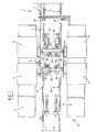
- the upper cross member of the upright then passes over the two detectors 21, 22 and the speed of the transfer bands 15 and 18 are then in no way modified; on the other hand when the lower crosspiece passes over the first detector 21, the speed of the transfer belts is reduced to be completely canceled when the lower crosspiece meets the second detector 22, where the frame is then in place for its equipment, as shown in figure 1.
- the fixed stations are intended to equip simultaneously the lower right and left angles of the frame and the mobile stations to equip simultaneously the upper right and left angles as well as possibly the intermediate zones of the uprights which must receive fittings intermediaries.
- these components will be for the fixed positions the angle supports and for the mobile positions the compass bearings and possibly the intermediate bearings in the case of uprights of great length.
- the upper and lower clamping devices which will be described more precisely below, are referenced in 23 and 24 for the clamping devices associated with the fixed stations 13 and 16 and in 25 and 26 for the clamping stations associated with the master mobile station 14 and the slave mobile station 17.
- the clamping equipment is symmetrical; the clamping device 23 is identical and symmetrical to the clamping device 24 and the clamping device 25 is identical and symmetrical to the clamping device 26.
- These last two devices 25 and 26 which are intended to supplement the first two 23 and 24 are not actually only stop devices.
- These four devices are mounted on elevators in order to be obscured by the passage of the frame and come to position in the upper position when they are put into operation.
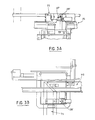
- FIGS. 2A and 2B show more precisely the clamping devices 23 and 24 associated with the fixed stations 13 and 16. More precisely, the clamping station 23 is shown, the other clamping station 24 being symmetrical with respect to it. the longitudinal axis of the machine and operating simultaneously.
- This device 23 is therefore raised at the level of the frame and intended to come to grip like a jaw the lower cross member TI thereof.
- It preferably consists of a roller along a vertical axis 27 which comes into abutment with the inner edge of the lower cross member TI and therefore which may possibly be of adequate shape to achieve this support in an optimal manner and from another roller relative to a vertical axis 28 which is movable, actuated by a jack 29 and is intended to be brought into contact with the outer edge of the lower cross member TI, which is then blocked between the two rollers 27 and 28.
- the frame is then immobilized with respect to the direction of travel by the rollers 27 and 28. In fact, as long as the mobile beam 12 is not immobilized, the frame must be able to move in lateral translation.
- the following operation consists in positioning the mobile stations relative to the frame. It is the master mobile station 14 which is moved, the other slave mobile station 17 being moved automatically simultaneously.
- the positioning of the master station and consequently of the slave station is carried out by means of two detectors 30 and 31 integral with the master mobile station 14 and which are visible on the Figure 1.
- the station 14 is translated on the fixed beam 11 until the detector 30 meets the upper cross member in the case of a single frame.
- the function of the detector 31 which, for its part, is positioned under the straight upright MD is intended to allow the positioning of the mobile stations 14, 17 in the case of a frame equipped with an intermediate crosspiece.
- the treatment is done in at least two stages, namely first of all positioning and treatment with respect to the upper cross member and the intermediate cross member, then positioning and treatment of the posts with respect to the cross member intermediate and lower cross member.
- the stop devices 25 and 26 are raised in order to complete the blocking of the upright in the treatment position. These two stations are actuated simultaneously and are constituted in an identical manner symmetrical with respect to the longitudinal direction of the machine.
- the right stop station 25 is described more precisely in FIGS. 3A and 3B, in the position which has just been described, the projecting members forming a stop 28 ′ of this stop device 25 once raised comes to position at 'interior of the frame facing the upper cross member and at a certain distance from the inside edge thereof.
- the four clamping devices 23, 24, 25 and 26 are also provided with detectors in order to precisely complete the positioning of the frame.
- the mobile beam 12 is moved backwards until the detectors fitted to the clamping devices 23 and 24 of the fixed stations 13 and 16 are concealed, and the mobile stations 14 and 17 are moved until the detector 27 ′ of the stop device 25 of the master mobile station 14 of the fixed beam is concealed.
- the treatment stations 13, 14, 16 and 17 are therefore positioned in a locked manner relative to the frame.
- the equipment in itself of the frame by these various components can then be achieved thanks to the tool modules constituting each of these stations.
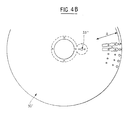
- FIGS. 4A and 4B show the two types of magazine trays 30 and 30 ′ intended to equip the preferred embodiment of the automatic machine.
- these trays are made of PVC.
- the fixed stations 13 and 16 which are intended to equip the lower angles of the upright using a bearing of angle supports at each angle are equipped with a store shelf 30 ′ said simple which as can be seen on FIG. 4B comprises a perimeter zone A preferably made up of cavities adapted so that the angle support bearings are fitted therein.
- the mobile stations 14 and 17 which are intended to equip on the one hand the upper angles of compass bearings but also possibly the intermediate zones of the amounts of intermediate bearings are provided with magazine trays 30; these comprise two concentric loading zones A1 and A2, one of which is intended to have a certain number of compass bearings and the other a certain number of intermediate bearings, the positioning of these components being carried out in a similar manner in the case of the plate 30 ′ by an adequate nesting cavity system.
- the plate 30 is put in place on a specific drive device giving it, on the one hand, a step-by-step rotation movement and, on the other hand, a movement in backward translation.
- the device for driving the plate 30 ′ intended to give it a simple step-by-step rotation movement can be deduced from the device described.
- This device for driving the tray 30 will be described more precisely with reference to FIGS. 5 and 6.
- the positioning of the tray trays 30 on this drive device is done by central fitting on a drive disc 33 and by radial locking on at least one tenon 33 ′ protruding from the drive disc 33 and fitting into the corresponding cavity 33 ⁇ of the magazine tray 30.
- This drive device therefore comprises a central shaft 34 fitted with a torque limiter and on the hub 35 of which is fixed by means of screws or the like the drive disc 33.
- the step-by-step actuation device for the drive disc 33 will now be described more precisely with reference to FIGS. 5 and 6.
- the drive disc 33 is a ring gear in the teeth of which comes mesh a pawl 36 actuated so as to carry out the step-by-step movement of this crown 33.
- This pawl 36 is actuated by means of a ratchet device 37 mounted at the end of the rod of a jack 38 operating back and forth and articulated at 39.
- the ratchet device 36 is itself mounted on an arm 40 articulated around the hub 35 of the central shaft 34.
- the tray tray drive device 30 ′ is therefore limited to the unit which has just been described.
- the drive device of the magazine tray 30 also allows displacement in translation over a certain travel back and forth to bring the component or components to the right of the gripper of the manipulator 31, which will be specified more far.
- This translational drive device is produced by a plate acting as a carriage 41 which is mounted on sliding axes. 42 preferably two in number by means of ball bushings 43 integral with this plate 41 and mounted at the end in a fixed manner on bearings 44 fixed to the chassis.
- the actuation per se is carried out by a jack 45, the end of the rod of which is articulated at 46 on the carriage plate 41 and the end of the body of which is articulated on the chassis.
- the store trays 30, 30 ′ are equipped with hole components cooperating with a set of photoelectric cells and optical fibers and controlling the rotation of the tray.
- the actuator 38 is again actuated until the magazine tray 30 or 30 ′ is positioned at a position where there is a component to be put in square.
- this actuation is determined so that if more than five parts are missing, for example, the mechanism stops in order to allow verification.
- This manipulator 31 which grips the appropriate component on the tray to position it on the upright to be fitted.
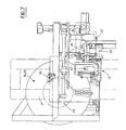
- This manipulator 31 is shown in Figure 7, it mainly comprises a rotary assembly around the axis 47 ′ supporting an arm 46 at the free end of which is arranged a clamp 47 with two jaws directed downwards.
- the movement of this manipulator 31 therefore consists of a semicircle symbolized by a dashed line in FIG.
- the step-by-step movement of the magazine tray 30, 30 ′ allows the grip of each of the components of one of the zones A1 or A2 while the translation of the assembly (magazine tray and device for step-by-step movement by ratchet) makes it possible to pass from one zone to the other, namely from the zone A1 to zone A2 and from zone A2 to zone A1.
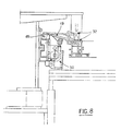
- the station shown in FIG. 7 is also equipped with a positioning template 32 described more precisely in FIG. 8.
- This template 32 is an accessory element whose usefulness will be specified now.
- Most of the window frame components, in particular on the bearings, are fitted with interlocking pins which facilitate and consolidate their attachment to the upright. In fact, it then suffices to generally drill two orifices in the upright, then to fit the studs in general two in number, then to install the fixing screws.
- the machine is equipped with a template 32 which is intended to guide the component in order to allow the screwing in of the orifices of the components, namely in the example described of the bearing or intermediate bearings.
- the template 32 is actuated by an articulation and jack system, more precisely it is articulated along a horizontal axis 48 on a carriage movable on the chassis of the station thanks to an arm 49 supporting in an articulated the rod of a jack 50 this jack acting when it is retracted to support the template 32 on the upright M and when it is out, to obscure the template 32 of the treatment area.
- each station comprises a drilling unit and a screwing unit.
- These drilling and screwing units must be moved vertically to fulfill their function, of course, but also must be moved horizontally to position themselves adequately at the location of the orifices to be produced intended to receive the studs of the components as well. as the right of the screw passages of each component.
- These drilling and screwing devices are therefore actuated by means of specific drive devices allowing horizontal positioning as a function of the part to be fixed. According to the preferred embodiment, this is in particular described for mobile stations 14, 17 which are intended to fix either compass bearings or intermediate bearings and therefore to allow at least two different sets of positioning for drilling and screwing.
- the tool units of fixed stations intended to fix only one type of tool can be deduced from this device described.
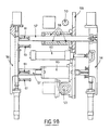
- FIG. 9A is a view in the horizontal plane of the drive unit for the working tools and makes it possible to see more precisely the displacement and adjustment devices perpendicular to the longitudinal direction of the machine and FIG. 2B is a view along C of this drive unit representing the devices for moving and adjusting the tools parallel to the longitudinal direction of the machine.
- the adjustment and displacement mechanism perpendicular to the longitudinal direction of the machine mainly consists of a support plate 51 mounted by means of ball bushings 52 on two horizontal sliding shafts 53.
- the actuation of the horizontal translation is achieved by a set of two jacks 54 which cause the displacement of the support plate 51 in accordance with the dashed line shown in FIG. 9A.
- the adjustment according to the different positions required is represented by a set of stops produced by the screws or bolts or the like 55.
- the drive unit in the direction parallel to the longitudinal axis of the machine is produced in a relatively equivalent manner. More specifically, the tool supports 56 are guided in translation by the shafts 57 sliding on the fixed chassis plate by means of ball bushing systems 59 and the tool support 56 is actuated by a system of jacks 60, the adjustment being carried out by stop against a set of screws or bolts or the like 61.
- the fixed post and the mobile post of one or the other of the beams will be active depending on whether the opening is left opening or right opening.
- the two stations then work simultaneously for the installation of the components located at the upper and lower corners of this sleeping frame.
- the mobile unit moves in a second step if it must ensure the installation of another intermediate element between these two components located in the corners.
- the mobile station therefore moves for an additional sequence and ensures a second intermediate landing installation. During this time, at least two of the three other stations ensure the clamping of the frame.
- the machine first selects the intermediate cross as an upper cross to carry out the sequences mentioned above when it is the lower part constituted by the lower cross of the frame and the intermediate cross member which is fitted with openings. If it is the upper part formed by the intermediate cross member and the upper cross member of the frame, the machine identifies the first immobilization of opening it from the fixed posts on the intermediate cross member and ensuring the sequences already described.
- the machine ensures the mounting of the components in the upper part, that is to say the first immobilization will be ensured by the fixed positions of the intermediate cross member, in a second step , the frame is placed and immobilized by the fixed posts on its lower crossmember.
- the machine described has four mobile or fixed workstations, but a single workstation alone can assemble all the components over the entire length of the frame and in this case the frame is automatically positioned on the workstation or the post automatically moves along each of the sleeping frames. In this case, the whole of this station is given a rotation of 180 °, and in this case, a device for inverting the components is produced by the rotation of the clamp.
Landscapes
- Engineering & Computer Science (AREA)
- Mechanical Engineering (AREA)
- Automatic Assembly (AREA)
- Automobile Manufacture Line, Endless Track Vehicle, Trailer (AREA)
Applications Claiming Priority (2)
| Application Number | Priority Date | Filing Date | Title |
|---|---|---|---|
| FR9002688A FR2659040B1 (fr) | 1990-03-02 | 1990-03-02 | Machine automatique de pose de composants sur dormants de porte ou fenetres. |
| FR9002688 | 1990-03-02 |
Publications (1)
| Publication Number | Publication Date |
|---|---|
| EP0444988A1 true EP0444988A1 (de) | 1991-09-04 |
Family
ID=9394343
Family Applications (1)
| Application Number | Title | Priority Date | Filing Date |
|---|---|---|---|
| EP91400308A Withdrawn EP0444988A1 (de) | 1990-03-02 | 1991-02-08 | Automatische Maschine zum Befestigen von Teilen auf Tür- oder Fensterpfosten |
Country Status (5)
| Country | Link |
|---|---|
| EP (1) | EP0444988A1 (de) |
| CA (1) | CA2035359A1 (de) |
| FI (1) | FI910451A7 (de) |
| FR (1) | FR2659040B1 (de) |
| NO (1) | NO910831L (de) |
Cited By (3)
| Publication number | Priority date | Publication date | Assignee | Title |
|---|---|---|---|---|
| DE19843269A1 (de) * | 1998-09-21 | 2000-03-30 | Roto Frank Ag | Verfahren zur maschinellen Montage von Beschlagteilen an Flügel- und/oder Blendrahmen von Fenstern, Türen oder dergleichen und Vorrichtung zur maschinellen Montage von Beschlagteilen an Flügel- und/oder Blendrahmen von Fenstern, Türen oder dergleichen |
| FR2913903A1 (fr) * | 2007-03-23 | 2008-09-26 | Jean Jacques Goubin | Installation pour l'assemblage d'elements de cadre dormant. |
| CN104191216A (zh) * | 2014-08-26 | 2014-12-10 | 昆山迈致治具科技有限公司 | 一种设备装配系统及设备装配方法 |
Families Citing this family (2)
| Publication number | Priority date | Publication date | Assignee | Title |
|---|---|---|---|---|
| CN109514223A (zh) * | 2018-12-21 | 2019-03-26 | 浙江硕和机器人科技有限公司 | 一种机身装配用的挡风圈上料装置 |
| CN113319788B (zh) * | 2021-05-11 | 2022-08-26 | 佛山市广韩门窗科技有限公司 | 一种铝合金门窗安装用防偏移的定位支撑机构 |
Citations (6)
| Publication number | Priority date | Publication date | Assignee | Title |
|---|---|---|---|---|
| US3772757A (en) * | 1972-06-26 | 1973-11-20 | M Goldstein | Machine for automatically attaching hinges to doors and jambs |
| DE2166857A1 (de) * | 1971-10-07 | 1976-05-26 | Gietzelt Kg Uniquick | Montagevorrichtung fuer moebelbeschlaege, insbesondere scharniere |
| EP0124763A1 (de) * | 1983-05-05 | 1984-11-14 | IMA-Norte Maschinenfabriken Klessmann GmbH & Co. | Vorrichtung zum Einpressen von Möbel-Montageteilen |
| FR2560091A1 (fr) * | 1984-01-24 | 1985-08-30 | Drouot Sa Ets | Machine-outil destinee a fixer des plaques ou profiles prealablement perfores a cet effet |
| EP0373991A1 (de) * | 1988-12-12 | 1990-06-20 | FERCO INTERNATIONAL Usine de Ferrures de BÀ¢timent Société à responsabilité limitée | Anlage zur Fertigstellung von Flügeln |
| EP0401094A1 (de) * | 1989-06-01 | 1990-12-05 | FERCO INTERNATIONAL Usine de Ferrures de BÀ¢timent Société à responsabilité limitée | Einrichtung zur Endbearbeitung von Fensterrahmen |
-
1990
- 1990-03-02 FR FR9002688A patent/FR2659040B1/fr not_active Expired - Lifetime
-
1991
- 1991-01-30 FI FI910451A patent/FI910451A7/fi unknown
- 1991-01-31 CA CA002035359A patent/CA2035359A1/fr not_active Abandoned
- 1991-02-08 EP EP91400308A patent/EP0444988A1/de not_active Withdrawn
- 1991-03-01 NO NO91910831A patent/NO910831L/no unknown
Patent Citations (6)
| Publication number | Priority date | Publication date | Assignee | Title |
|---|---|---|---|---|
| DE2166857A1 (de) * | 1971-10-07 | 1976-05-26 | Gietzelt Kg Uniquick | Montagevorrichtung fuer moebelbeschlaege, insbesondere scharniere |
| US3772757A (en) * | 1972-06-26 | 1973-11-20 | M Goldstein | Machine for automatically attaching hinges to doors and jambs |
| EP0124763A1 (de) * | 1983-05-05 | 1984-11-14 | IMA-Norte Maschinenfabriken Klessmann GmbH & Co. | Vorrichtung zum Einpressen von Möbel-Montageteilen |
| FR2560091A1 (fr) * | 1984-01-24 | 1985-08-30 | Drouot Sa Ets | Machine-outil destinee a fixer des plaques ou profiles prealablement perfores a cet effet |
| EP0373991A1 (de) * | 1988-12-12 | 1990-06-20 | FERCO INTERNATIONAL Usine de Ferrures de BÀ¢timent Société à responsabilité limitée | Anlage zur Fertigstellung von Flügeln |
| EP0401094A1 (de) * | 1989-06-01 | 1990-12-05 | FERCO INTERNATIONAL Usine de Ferrures de BÀ¢timent Société à responsabilité limitée | Einrichtung zur Endbearbeitung von Fensterrahmen |
Cited By (4)
| Publication number | Priority date | Publication date | Assignee | Title |
|---|---|---|---|---|
| DE19843269A1 (de) * | 1998-09-21 | 2000-03-30 | Roto Frank Ag | Verfahren zur maschinellen Montage von Beschlagteilen an Flügel- und/oder Blendrahmen von Fenstern, Türen oder dergleichen und Vorrichtung zur maschinellen Montage von Beschlagteilen an Flügel- und/oder Blendrahmen von Fenstern, Türen oder dergleichen |
| FR2913903A1 (fr) * | 2007-03-23 | 2008-09-26 | Jean Jacques Goubin | Installation pour l'assemblage d'elements de cadre dormant. |
| CN104191216A (zh) * | 2014-08-26 | 2014-12-10 | 昆山迈致治具科技有限公司 | 一种设备装配系统及设备装配方法 |
| CN104191216B (zh) * | 2014-08-26 | 2017-09-22 | 昆山迈致治具科技有限公司 | 一种设备装配系统及设备装配方法 |
Also Published As
| Publication number | Publication date |
|---|---|
| NO910831D0 (no) | 1991-03-01 |
| FR2659040A1 (fr) | 1991-09-06 |
| FI910451A0 (fi) | 1991-01-30 |
| NO910831L (no) | 1991-09-03 |
| FI910451A7 (fi) | 1991-09-03 |
| CA2035359A1 (fr) | 1991-09-03 |
| FR2659040B1 (fr) | 1992-05-15 |
Similar Documents
| Publication | Publication Date | Title |
|---|---|---|
| FR2657071A1 (fr) | Appareil convoyeur pour la manutention d'articles volumineux. | |
| EP0069661B1 (de) | Automatische Blechbiegemaschine | |
| EP0387124A1 (de) | Vorrichtung zum automatischen Eindrücken von Dichtungen, insbesondere von einer Dichtung in einer Nut eines Fensters | |
| FR2574691A1 (fr) | Procede et appareil pour monter des pieces des deux cotes d'un corps principal, notamment la carrosserie d'un vehicule automobile | |
| FR2601608A1 (fr) | Procede et mecanisme d'attache et de separation de porte d'automobile. | |
| FR2717764A1 (fr) | Appareil de montage pour chaine de fabrication. | |
| FR2541162A1 (fr) | Appareil pour l'assemblage de la caisse d'une automobile | |
| FR2675482A1 (fr) | Dispositif de manutention destine au convoyage de panneaux, notamment des panneaux lateraux constituant la carrosserie d'un vehicule. | |
| EP0388296B1 (de) | Interventionsvorrichtung, insbesondere zur Prüfung, Inspektion und Wartung von Wärmeaustauschern | |
| CA2035359A1 (fr) | Machine automatique de pose de composants sur dormants de portes ou fenetres | |
| EP0329583A1 (de) | Vorrichtung zum Zusammenbauen von Eckumlenkungsteilen | |
| FR2709295A1 (fr) | Appareil pour le chargement de pièces comprenant une navette et une monture pivotante support de pièces entraînées en harmonie. | |
| CA2040359A1 (fr) | Machine automatique de pose de gaches sur des dormants de fenetres ou de porte-fenetres | |
| FR2587058A1 (fr) | Dispositif d'assemblage et d'articulation pour porte montee sur pivot | |
| CA2064663A1 (fr) | Machine de pose de ferrures sur des profiles, notamment de pose de gaches sur des profiles destines, apres assemblage ulterieur, a constituer des dormants de porte ou fenetre | |
| EP1089850A1 (de) | Ladevorrichtung einer werkzeugmaschine mit zuarbeitungs-stangen | |
| EP0876946B1 (de) | Türschliesser, damit ausgerüstete Tür und Schienenfahrzeug mit mindestens einer derartigen Vorrichtung und/oder Tür | |
| FR2684228A1 (fr) | Appareil de maintenance avec commande a distance. | |
| FR2662627A1 (fr) | Machine pour la pose automatique de ferrures. | |
| FR2631099A1 (fr) | Dispositif de positionnement de pieces metalliques contre un element metallique porteur allonge | |
| FR2908060A1 (fr) | Machine de planage d'une bande metallique | |
| FR2925014A1 (fr) | Dispositif de montage d'au moins une piece sur un element de structure d'un vehicule automobile | |
| FR2644093A1 (fr) | Machine pour la pose automatique de joint souple, en particulier d'un joint exterieur dans une rainure de vantail | |
| FR2557013A1 (fr) | Presse pour regler et inspecter des moules | |
| BE1003290A7 (fr) | Procede et installation d'assemblage de chassis. |
Legal Events
| Date | Code | Title | Description |
|---|---|---|---|
| PUAI | Public reference made under article 153(3) epc to a published international application that has entered the european phase |
Free format text: ORIGINAL CODE: 0009012 |
|
| AK | Designated contracting states |
Kind code of ref document: A1 Designated state(s): AT BE CH DE DK ES GB GR IT LI LU NL SE |
|
| 17P | Request for examination filed |
Effective date: 19911129 |
|
| 17Q | First examination report despatched |
Effective date: 19930208 |
|
| STAA | Information on the status of an ep patent application or granted ep patent |
Free format text: STATUS: THE APPLICATION IS DEEMED TO BE WITHDRAWN |
|
| 18D | Application deemed to be withdrawn |
Effective date: 19930619 |
|
| PGFP | Annual fee paid to national office [announced via postgrant information from national office to epo] |
Ref country code: LU Payment date: 19960201 Year of fee payment: 6 |