EP0444995A1 - Adsorptionsgefäss und Vorrichtung zur Trennung von Gasmischungen - Google Patents
Adsorptionsgefäss und Vorrichtung zur Trennung von Gasmischungen Download PDFInfo
- Publication number
- EP0444995A1 EP0444995A1 EP91400389A EP91400389A EP0444995A1 EP 0444995 A1 EP0444995 A1 EP 0444995A1 EP 91400389 A EP91400389 A EP 91400389A EP 91400389 A EP91400389 A EP 91400389A EP 0444995 A1 EP0444995 A1 EP 0444995A1
- Authority
- EP
- European Patent Office
- Prior art keywords
- gas
- passage
- dip tube
- bottle
- enclosure
- Prior art date
- Legal status (The legal status is an assumption and is not a legal conclusion. Google has not performed a legal analysis and makes no representation as to the accuracy of the status listed.)
- Withdrawn
Links
- 238000001179 sorption measurement Methods 0.000 title claims abstract description 29
- 239000000203 mixture Substances 0.000 title claims description 8
- 239000003463 adsorbent Substances 0.000 claims abstract description 16
- 239000008246 gaseous mixture Substances 0.000 claims abstract description 5
- 239000000470 constituent Substances 0.000 claims abstract description 3
- 238000000926 separation method Methods 0.000 claims abstract description 3
- 238000009434 installation Methods 0.000 claims description 9
- 239000008187 granular material Substances 0.000 claims description 6
- 239000002250 absorbent Substances 0.000 claims 1
- 230000002745 absorbent Effects 0.000 claims 1
- 239000007789 gas Substances 0.000 abstract description 32
- 238000004519 manufacturing process Methods 0.000 abstract description 9
- 239000001257 hydrogen Substances 0.000 abstract description 3
- 229910052739 hydrogen Inorganic materials 0.000 abstract description 3
- UFHFLCQGNIYNRP-UHFFFAOYSA-N Hydrogen Chemical compound [H][H] UFHFLCQGNIYNRP-UHFFFAOYSA-N 0.000 abstract description 2
- 238000003860 storage Methods 0.000 description 14
- 238000010926 purge Methods 0.000 description 4
- 238000010828 elution Methods 0.000 description 3
- IJGRMHOSHXDMSA-UHFFFAOYSA-N Atomic nitrogen Chemical compound N#N IJGRMHOSHXDMSA-UHFFFAOYSA-N 0.000 description 2
- 238000009826 distribution Methods 0.000 description 2
- 238000003780 insertion Methods 0.000 description 2
- 230000037431 insertion Effects 0.000 description 2
- 230000006978 adaptation Effects 0.000 description 1
- 230000000712 assembly Effects 0.000 description 1
- 238000000429 assembly Methods 0.000 description 1
- 238000012550 audit Methods 0.000 description 1
- 238000010276 construction Methods 0.000 description 1
- 125000004122 cyclic group Chemical group 0.000 description 1
- 150000002431 hydrogen Chemical class 0.000 description 1
- 239000002184 metal Substances 0.000 description 1
- VNWKTOKETHGBQD-UHFFFAOYSA-N methane Chemical compound C VNWKTOKETHGBQD-UHFFFAOYSA-N 0.000 description 1
- 238000000034 method Methods 0.000 description 1
- 229910052757 nitrogen Inorganic materials 0.000 description 1
- 238000000746 purification Methods 0.000 description 1
- 230000001172 regenerating effect Effects 0.000 description 1
- 239000002912 waste gas Substances 0.000 description 1
Images


Classifications
-
- F—MECHANICAL ENGINEERING; LIGHTING; HEATING; WEAPONS; BLASTING
- F17—STORING OR DISTRIBUTING GASES OR LIQUIDS
- F17C—VESSELS FOR CONTAINING OR STORING COMPRESSED, LIQUEFIED OR SOLIDIFIED GASES; FIXED-CAPACITY GAS-HOLDERS; FILLING VESSELS WITH, OR DISCHARGING FROM VESSELS, COMPRESSED, LIQUEFIED, OR SOLIDIFIED GASES
- F17C11/00—Use of gas-solvents or gas-sorbents in vessels
- F17C11/005—Use of gas-solvents or gas-sorbents in vessels for hydrogen
-
- B—PERFORMING OPERATIONS; TRANSPORTING
- B01—PHYSICAL OR CHEMICAL PROCESSES OR APPARATUS IN GENERAL
- B01D—SEPARATION
- B01D53/00—Separation of gases or vapours; Recovering vapours of volatile solvents from gases; Chemical or biological purification of waste gases, e.g. engine exhaust gases, smoke, fumes, flue gases, aerosols
- B01D53/02—Separation of gases or vapours; Recovering vapours of volatile solvents from gases; Chemical or biological purification of waste gases, e.g. engine exhaust gases, smoke, fumes, flue gases, aerosols by adsorption, e.g. preparative gas chromatography
- B01D53/04—Separation of gases or vapours; Recovering vapours of volatile solvents from gases; Chemical or biological purification of waste gases, e.g. engine exhaust gases, smoke, fumes, flue gases, aerosols by adsorption, e.g. preparative gas chromatography with stationary adsorbents
- B01D53/0407—Constructional details of adsorbing systems
-
- B—PERFORMING OPERATIONS; TRANSPORTING
- B01—PHYSICAL OR CHEMICAL PROCESSES OR APPARATUS IN GENERAL
- B01D—SEPARATION
- B01D2256/00—Main component in the product gas stream after treatment
- B01D2256/16—Hydrogen
-
- B—PERFORMING OPERATIONS; TRANSPORTING
- B01—PHYSICAL OR CHEMICAL PROCESSES OR APPARATUS IN GENERAL
- B01D—SEPARATION
- B01D2257/00—Components to be removed
- B01D2257/10—Single element gases other than halogens
- B01D2257/102—Nitrogen
-
- B—PERFORMING OPERATIONS; TRANSPORTING
- B01—PHYSICAL OR CHEMICAL PROCESSES OR APPARATUS IN GENERAL
- B01D—SEPARATION
- B01D2257/00—Components to be removed
- B01D2257/50—Carbon oxides
- B01D2257/502—Carbon monoxide
-
- B—PERFORMING OPERATIONS; TRANSPORTING
- B01—PHYSICAL OR CHEMICAL PROCESSES OR APPARATUS IN GENERAL
- B01D—SEPARATION
- B01D2257/00—Components to be removed
- B01D2257/50—Carbon oxides
- B01D2257/504—Carbon dioxide
-
- B—PERFORMING OPERATIONS; TRANSPORTING
- B01—PHYSICAL OR CHEMICAL PROCESSES OR APPARATUS IN GENERAL
- B01D—SEPARATION
- B01D2259/00—Type of treatment
- B01D2259/40—Further details for adsorption processes and devices
- B01D2259/402—Further details for adsorption processes and devices using two beds
-
- B—PERFORMING OPERATIONS; TRANSPORTING
- B01—PHYSICAL OR CHEMICAL PROCESSES OR APPARATUS IN GENERAL
- B01D—SEPARATION
- B01D2259/00—Type of treatment
- B01D2259/45—Gas separation or purification devices adapted for specific applications
- B01D2259/4525—Gas separation or purification devices adapted for specific applications for storage and dispensing systems
-
- B—PERFORMING OPERATIONS; TRANSPORTING
- B01—PHYSICAL OR CHEMICAL PROCESSES OR APPARATUS IN GENERAL
- B01D—SEPARATION
- B01D53/00—Separation of gases or vapours; Recovering vapours of volatile solvents from gases; Chemical or biological purification of waste gases, e.g. engine exhaust gases, smoke, fumes, flue gases, aerosols
- B01D53/02—Separation of gases or vapours; Recovering vapours of volatile solvents from gases; Chemical or biological purification of waste gases, e.g. engine exhaust gases, smoke, fumes, flue gases, aerosols by adsorption, e.g. preparative gas chromatography
- B01D53/04—Separation of gases or vapours; Recovering vapours of volatile solvents from gases; Chemical or biological purification of waste gases, e.g. engine exhaust gases, smoke, fumes, flue gases, aerosols by adsorption, e.g. preparative gas chromatography with stationary adsorbents
- B01D53/0407—Constructional details of adsorbing systems
- B01D53/0446—Means for feeding or distributing gases
-
- Y—GENERAL TAGGING OF NEW TECHNOLOGICAL DEVELOPMENTS; GENERAL TAGGING OF CROSS-SECTIONAL TECHNOLOGIES SPANNING OVER SEVERAL SECTIONS OF THE IPC; TECHNICAL SUBJECTS COVERED BY FORMER USPC CROSS-REFERENCE ART COLLECTIONS [XRACs] AND DIGESTS
- Y02—TECHNOLOGIES OR APPLICATIONS FOR MITIGATION OR ADAPTATION AGAINST CLIMATE CHANGE
- Y02C—CAPTURE, STORAGE, SEQUESTRATION OR DISPOSAL OF GREENHOUSE GASES [GHG]
- Y02C20/00—Capture or disposal of greenhouse gases
- Y02C20/40—Capture or disposal of greenhouse gases of CO2
-
- Y—GENERAL TAGGING OF NEW TECHNOLOGICAL DEVELOPMENTS; GENERAL TAGGING OF CROSS-SECTIONAL TECHNOLOGIES SPANNING OVER SEVERAL SECTIONS OF THE IPC; TECHNICAL SUBJECTS COVERED BY FORMER USPC CROSS-REFERENCE ART COLLECTIONS [XRACs] AND DIGESTS
- Y02—TECHNOLOGIES OR APPLICATIONS FOR MITIGATION OR ADAPTATION AGAINST CLIMATE CHANGE
- Y02E—REDUCTION OF GREENHOUSE GAS [GHG] EMISSIONS, RELATED TO ENERGY GENERATION, TRANSMISSION OR DISTRIBUTION
- Y02E60/00—Enabling technologies; Technologies with a potential or indirect contribution to GHG emissions mitigation
- Y02E60/30—Hydrogen technology
- Y02E60/32—Hydrogen storage
Definitions
- the present invention relates to an adsorption enclosure for separation of a constituent of a gaseous mixture, of the type with an elongated structure incorporating at least one adsorbent product in granular form and having gas intake and withdrawal means ensuring circulation of the gas in the longitudinal direction of said enclosure.
- Such adsorption chambers are generally used in a cyclic process for regenerating the adsorbent by pressure variation ("PSA" type) and for this purpose are present in an installation in the form of one or more columns arranged vertically or horizontally, each being equipped with gas intake means at one end of the column and gas withdrawal means at the other end of the column.
- PSA pressure variation
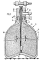
- an enclosure is a gas cylinder with a closed bottom and a cylindrical side wall ending in a neck, which is equipped with intake-withdrawal means in the form of an intake-withdrawal head with a first axial passage extending into a dip tube at a short distance from the bottom of the bottle and a second passage opening into the interior of the bottle at said bottle neck.
- the invention also relates to an installation for separating a gaseous mixture, of the type comprising a plurality of adsorption chambers, where appropriate a storage capacity of gas mixture to be treated, if necessary a storage capacity for the treated gas, if necessary a storage capacity for elution-purge gas or other capacities necessary for any PSA-type pressure variation cycle, all interconnected by pipes and valves so as to ensure, sequentially and for each adsorption chamber, a pressure production step, a depressurization step, if necessary an elution-purge step at low pressure, a repressurization step at pressure and which is characterized in that the said adsorption chambers and the possible storage capacities are formed by a plurality of bottles of standardized dimensions, where appropriate grouped on inlet-withdrawal ramps, the bottles forming adsorption chambers being of the type described above.
- adsorption bottles from a commercially available bottle, of relatively low capacity, therefore leads to the creation of modular assemblies with one or more adsorption bottles, generally (but not necessarily) associated with a plurality of storage bottles, distributed in an appropriate number depending on whether it is the storage of the mixture to be treated, the storage of the treated mixture, or the storage of an elution gas or other storage, the whole being able to be housed in a single support frame.
- an adsorption bottle 11 is formed of a bottle proper, of conventional shape 12 with a side wall 13 and a bottom 14 which is here shown with a concave shape, but which could be convex or flat.
- the side wall 13 is restricted upwards into a neck 15 forming a passage 16 having a conical entry portion 16 ′ followed, towards the inside of the bottle, by a cylindrical passage 16 ⁇ .
- An intake-withdrawal head 17 is mounted in the neck 15 and this head 17 comprises for this purpose a nozzle 18 engaged with thread in the part 16 ′, in which it is kept sealed.
- This endpiece 18 with axial passage 19 extends into a large body 20 with an axial passage opening into a cavity 21 communicating with a transverse passage 22.
- a first gas passage is made via the ramp 24, the core 23, the dip tube 25 extending from an external end through the neck of the bottle 15 to the immediate vicinity of the bottom of the bottle 14, on the other hand, a second passage via the conduit 22, the interstitial space 26 between passages 21 - 19 and dip tube 25 to open immediately at 27 internally in the vicinity of the neck 15.
- Such an adsorption bottle 11 is produced first by filling the bottle proper (deprived of its intake-withdrawal head) with granulated adsorbent product 28, so as to however leave a free volume allowing the subsequent insertion of the dip tube 25 of the intake-withdrawal head.
- the adsorption bottle operates at the bottom and the gas to be treated is introduced through the conduit 22 to pass into the second passage 26 at the top of the adsorbent and to flow from downward along arrow F through the adsorbent mass 28, and be collected at the lower end 30 of the dip tube 25 which conveys the treated gas to the withdrawal manifold 24.
- the interstitial passage 26 of the gas inlet to be treated is of section greater than the internal section of the dip tube 25 forming the withdrawal passage, and preferably in the ratio of the admitted and withdrawn flow rates (the latter being less than the admitted flow rate by a value equal to the gas flow trapped in the adsorbent).
- the first passage formed by the dip tube 25 serves as an intake passage (gas circulating upwardly in the adsorbent mass according to arrow F ′ to be collected at the level of the second passage 26 serving as a withdrawal passage), it is the section of the dip tube 25 which would be greater than the section of the annular passage 26.
- an adsorption bottle of the same type with a flat bottom 14 is here always placed vertically, but with the bottom 14 in the high position and the intake-withdrawal head in the low position.
- a little less adsorbent granule was introduced, so as to provide an upper gas distribution zone 29 free of any granule, in which the end 30 of the dip tube 25 emerges.
- the gas can be admitted by the dip tube 25 (downward flow along arrow F), or collected by the dip tube 25 (upward flow along arrow F ′).
- the dip tube 25 can be made of two concentric tubes 25 ′ and 25 ⁇ sliding one inside the other and preferably its end portion 30 is conical in shape to facilitate insertion of the tube into the mass of adsorbent granule. It is provided at its end with small diameter orifices 31 and / or narrow slots 32 avoiding any risk of introducing adsorbent granules.
- a purification installation is here equipped with two adsorption bottles 41, 42, with a storage capacity for gas to be treated 43 formed of two groups 44 and 45 each comprising four bottles 46, 47, 48, 49 (46 ′, 47 ′, 48 ′, 49 ′) connected in parallel on two distributing ramps 50 and 51, connected to a supply line 52 and to a connection line 53 to the bottles 41 and 42, incorporating a solenoid valve 54 and flow limiter 55 charging circuit in parallel on a solenoid valve 56 and flow limiter 57 recompression circuit, a pressure regulator 58 (which can be replaced by a flow meter) inlet 59, 60 to the bottles 41, 42 respectively.
- a solenoid valve 54 and flow limiter 55 charging circuit in parallel on a solenoid valve 56 and flow limiter 57 recompression circuit
- a pressure regulator 58 (which can be replaced by a flow meter) inlet 59, 60 to the bottles 41, 42 respectively.
- a waste gas circuit 61 incorporates, for each bottle 41, 42, individual lines 62, (63) with solenoid valves 64, (65) and a common discharge line 66 with flow limiter 67.
- a production gas circuit incorporates pipes 68, 69 bridged by a pipe 70 with valves 71, 72 and flow limiter 73, and continuing with solenoid valves 74 and 75 to a common double circuit pipe in parallel, 77 (78), incorporating each two valves 79 and 79 ′, a flow regulator 80 on line 77 and a pressure (or flow) regulator 81 on line 78, leading to two ramps 82, 83 each serving a group 84 (85) of three cylinders 86, 87, 88 (86 ′, 87 ′, 88 ′) for storage of treated gas, connected to a common manifold 89 for production of treated gas with regulator 90.
- the production lines 68, 69 are each connected by a line 91 (92) with valve 93 (94) to a common line 95 incorporating two parallel circuits 96 (97) with valve 100, 101 and regulator 98 (99) leading to two 102-102 ′ purge elution gas storage bottles.
- Storage bottles whether gas to be treated (cylinders 46 (46 ′), 47 (47 ′), ..., treated gas 86 (86 ′), 87 (87 ′), elution gas- purge 102 (102 ′) are here simple bottles, with a simple filling-racking head, single-pass neck, without dip tube or adsorbent, unlike adsorption bottles 41 and 42 which conform to the embodiments described in Figures 1 and 2.
- these bottles are also commercial bottles, preferably - but this is not essential - of the same standardized structure and capacity as the bottles from which the adsorption bottles 41 and 42 are produced .
- All these bottles, whether adsorption or storage are grouped, with a pipe and valve in one or more bundle (s) of bottles in a metal frame-support easily movable by crane and truck.
- the main application of the invention is the production of hydrogen from industrial mixtures incorporating, in addition to hydrogen, nitrogen, CH4, CO, CO2, CnHn or other mixture at flow rates of 20 to 100 N / m3 / h, and at pressures from 1 to 200 bars.
Landscapes
- Engineering & Computer Science (AREA)
- Chemical & Material Sciences (AREA)
- Mechanical Engineering (AREA)
- General Engineering & Computer Science (AREA)
- Analytical Chemistry (AREA)
- General Chemical & Material Sciences (AREA)
- Oil, Petroleum & Natural Gas (AREA)
- Chemical Kinetics & Catalysis (AREA)
- Separation Of Gases By Adsorption (AREA)
- Filling Or Discharging Of Gas Storage Vessels (AREA)
Applications Claiming Priority (2)
| Application Number | Priority Date | Filing Date | Title |
|---|---|---|---|
| FR9002615A FR2659030B1 (fr) | 1990-03-02 | 1990-03-02 | Enceinte et installation d'absorption pour separation des melanges gazeux. |
| FR9002615 | 1990-03-02 |
Publications (1)
| Publication Number | Publication Date |
|---|---|
| EP0444995A1 true EP0444995A1 (de) | 1991-09-04 |
Family
ID=9394305
Family Applications (1)
| Application Number | Title | Priority Date | Filing Date |
|---|---|---|---|
| EP91400389A Withdrawn EP0444995A1 (de) | 1990-03-02 | 1991-02-15 | Adsorptionsgefäss und Vorrichtung zur Trennung von Gasmischungen |
Country Status (5)
| Country | Link |
|---|---|
| US (1) | US5133787A (de) |
| EP (1) | EP0444995A1 (de) |
| JP (1) | JPH0568838A (de) |
| CA (1) | CA2037370A1 (de) |
| FR (1) | FR2659030B1 (de) |
Cited By (1)
| Publication number | Priority date | Publication date | Assignee | Title |
|---|---|---|---|---|
| WO2009000357A3 (de) * | 2007-06-27 | 2009-06-11 | Bluecher Gmbh | Speicherbehälter für gasförmige krafstoffe und dessen anwendung |
Families Citing this family (32)
| Publication number | Priority date | Publication date | Assignee | Title |
|---|---|---|---|---|
| US5575833A (en) * | 1992-09-25 | 1996-11-19 | Parker-Hannifin Corporation | Refrigerant recycling system and apparatus |
| US5518528A (en) * | 1994-10-13 | 1996-05-21 | Advanced Technology Materials, Inc. | Storage and delivery system for gaseous hydride, halide, and organometallic group V compounds |
| US5704967A (en) * | 1995-10-13 | 1998-01-06 | Advanced Technology Materials, Inc. | Fluid storage and delivery system comprising high work capacity physical sorbent |
| US6204180B1 (en) | 1997-05-16 | 2001-03-20 | Advanced Technology Materials, Inc. | Apparatus and process for manufacturing semiconductor devices, products and precursor structures utilizing sorbent-based fluid storage and dispensing system for reagent delivery |
| US6132492A (en) * | 1994-10-13 | 2000-10-17 | Advanced Technology Materials, Inc. | Sorbent-based gas storage and delivery system for dispensing of high-purity gas, and apparatus and process for manufacturing semiconductor devices, products and precursor structures utilizing same |
| US5707424A (en) * | 1994-10-13 | 1998-01-13 | Advanced Technology Materials, Inc. | Process system with integrated gas storage and delivery unit |
| US6083298A (en) * | 1994-10-13 | 2000-07-04 | Advanced Technology Materials, Inc. | Process for fabricating a sorbent-based gas storage and dispensing system, utilizing sorbent material pretreatment |
| US5916245A (en) * | 1996-05-20 | 1999-06-29 | Advanced Technology Materials, Inc. | High capacity gas storage and dispensing system |
| FR2754788B1 (fr) * | 1996-10-22 | 1998-12-24 | Nor Stick | Flacon de produit a pulveriser |
| US5676735A (en) * | 1996-10-31 | 1997-10-14 | Advanced Technology Materials, Inc. | Reclaiming system for gas recovery from decommissioned gas storage and dispensing vessels and recycle of recovered gas |
| US6027547A (en) * | 1997-05-16 | 2000-02-22 | Advanced Technology Materials, Inc. | Fluid storage and dispensing vessel with modified high surface area solid as fluid storage medium |
| US6019823A (en) * | 1997-05-16 | 2000-02-01 | Advanced Technology Materials, Inc. | Sorbent-based fluid storage and dispensing vessel with replaceable sorbent cartridge members |
| US5985008A (en) * | 1997-05-20 | 1999-11-16 | Advanced Technology Materials, Inc. | Sorbent-based fluid storage and dispensing system with high efficiency sorbent medium |
| US5851270A (en) * | 1997-05-20 | 1998-12-22 | Advanced Technology Materials, Inc. | Low pressure gas source and dispensing apparatus with enhanced diffusive/extractive means |
| US5980608A (en) * | 1998-01-07 | 1999-11-09 | Advanced Technology Materials, Inc. | Throughflow gas storage and dispensing system |
| US6406519B1 (en) * | 1998-03-27 | 2002-06-18 | Advanced Technology Materials, Inc. | Gas cabinet assembly comprising sorbent-based gas storage and delivery system |
| US6660063B2 (en) | 1998-03-27 | 2003-12-09 | Advanced Technology Materials, Inc | Sorbent-based gas storage and delivery system |
| US6070576A (en) * | 1998-06-02 | 2000-06-06 | Advanced Technology Materials, Inc. | Adsorbent-based storage and dispensing system |
| US6557591B2 (en) * | 2001-07-17 | 2003-05-06 | Air Products And Chemicals, Inc. | Bulk gas built-in purifier with dual valve bulk container |
| US7105037B2 (en) * | 2002-10-31 | 2006-09-12 | Advanced Technology Materials, Inc. | Semiconductor manufacturing facility utilizing exhaust recirculation |
| US6991671B2 (en) * | 2002-12-09 | 2006-01-31 | Advanced Technology Materials, Inc. | Rectangular parallelepiped fluid storage and dispensing vessel |
| USD545393S1 (en) | 2002-12-09 | 2007-06-26 | Advanced Technology Materials, Inc. | Rectangular parallelepiped fluid storage and dispensing vessel |
| US6743278B1 (en) | 2002-12-10 | 2004-06-01 | Advanced Technology Materials, Inc. | Gas storage and dispensing system with monolithic carbon adsorbent |
| US7494530B2 (en) * | 2002-12-10 | 2009-02-24 | Advanced Technology Materials, Inc. | Gas storage and dispensing system with monolithic carbon adsorbent |
| US8002880B2 (en) | 2002-12-10 | 2011-08-23 | Advanced Technology Materials, Inc. | Gas storage and dispensing system with monolithic carbon adsorbent |
| GB2398522A (en) * | 2003-02-18 | 2004-08-25 | Air Prod & Chem | Apparatus for the purification of gasses. |
| US20070173193A1 (en) * | 2005-12-16 | 2007-07-26 | Li Richard Q | Dangerous Mail Handler |
| US8679231B2 (en) | 2011-01-19 | 2014-03-25 | Advanced Technology Materials, Inc. | PVDF pyrolyzate adsorbent and gas storage and dispensing system utilizing same |
| FI20115265A0 (fi) * | 2011-03-17 | 2011-03-17 | Rami Hakala | Menetelmä ja suodatusjärjestely kaasuprosessissa |
| EP2855009A4 (de) | 2012-05-29 | 2016-04-13 | Entegris Inc | Kohlenstoffadsorptionsmittel zur entfernung von schwefelwasserstoff aus gasen und regenerierung des adsorptionsmittels |
| WO2019013910A1 (en) * | 2017-07-11 | 2019-01-17 | Cady Kevin J | PSEUDOPHACTIC INTRAOCULAR CONTACT LENS WITH CAPSULAR WALL SHEET FASTENING MECHANISM AND SYSTEM AND METHOD THEREOF |
| US11815433B2 (en) * | 2019-05-03 | 2023-11-14 | Shimadzu Corporation | Adsorption apparatus and chemiluminescence type nitrogen oxide concentration meter |
Citations (5)
| Publication number | Priority date | Publication date | Assignee | Title |
|---|---|---|---|---|
| DE852538C (de) * | 1949-10-06 | 1952-10-16 | Metallgesellschaft Ag | Adsorber |
| FR2215544A1 (de) * | 1973-01-29 | 1974-08-23 | Philips Nv | |
| US4162289A (en) * | 1977-02-25 | 1979-07-24 | Internacional de Ciencia y Tecnologia, S.A. | Filter unit for avoiding environmental pollution in cemeteries |
| US4373938A (en) * | 1981-09-11 | 1983-02-15 | Greene & Kellogg, Incorporated | Modular industrial oxygen concentrator |
| EP0250627A1 (de) * | 1986-06-30 | 1988-01-07 | Seitetsu Kagaku Co., Ltd. | Adsorptionsanlage |
Family Cites Families (19)
| Publication number | Priority date | Publication date | Assignee | Title |
|---|---|---|---|---|
| US2359959A (en) * | 1944-10-10 | Electrical ignition system | ||
| US780682A (en) * | 1903-09-21 | 1905-01-24 | Joseph Posch | Combined trap, filter, and air-distributer. |
| US1706676A (en) * | 1925-11-05 | 1929-03-26 | Jens A Paasche | Air cleaner and separator |
| US1821549A (en) * | 1927-01-15 | 1931-09-01 | E K Medical Gas Lab Inc | Apparatus for dehydrating and purifying gases |
| US2669318A (en) * | 1950-12-07 | 1954-02-16 | Southwick W Briggs | Filter and adsorber for fluid treatment |
| US2758719A (en) * | 1953-01-22 | 1956-08-14 | Ansul Chemical Co | Dehydrator |
| US3080977A (en) * | 1960-05-06 | 1963-03-12 | Henry Valve Co | Drier fitting and assembly |
| US3353339A (en) * | 1964-10-08 | 1967-11-21 | Selas Corp Of America | Gas cleaner |
| US3490205A (en) * | 1967-11-30 | 1970-01-20 | Nasa | High pressure gas filter system |
| US3581782A (en) * | 1968-12-23 | 1971-06-01 | Burdsall & Ward Co | Vapor emission control system |
| US3785164A (en) * | 1972-05-17 | 1974-01-15 | Virginia Chemicals Inc | Precharged receiver drier for automobile air conditioning systems |
| DD129169A1 (de) * | 1976-12-28 | 1978-01-04 | Ulf Weinrich | Transportable vorrichtung zur nachreinigung von technischen gasen |
| US4322228A (en) * | 1977-10-06 | 1982-03-30 | The Bendix Corporation | Pneumatically actuated electronic control for a fluid mixture adsorption separator |
| JPS5594618A (en) * | 1979-01-10 | 1980-07-18 | Shintouhoku Kagaku Kogyo Kk | Adsorber for natural zeolite at low temperature |
| DD236678A1 (de) * | 1985-04-29 | 1986-06-18 | Leuna Werke Veb | Vorrichtung zur adsorption und zur desorption von gasen |
| US4659467A (en) * | 1985-07-15 | 1987-04-21 | Spearman Michael R | Spin connection adsorption filter |
| US4875911A (en) * | 1986-07-22 | 1989-10-24 | Ckd Kabushiki Kaisha | Apparatus for separating gaseous mixtures |
| DK155979C (da) * | 1987-05-20 | 1989-10-30 | Haldor Topsoe As | Fordelingselement til fordeling af gas til en reaktor |
| US4750465A (en) * | 1987-07-31 | 1988-06-14 | General Motors Corporation | Fuel vapor storage canister |
-
1990
- 1990-03-02 FR FR9002615A patent/FR2659030B1/fr not_active Expired - Fee Related
-
1991
- 1991-02-15 EP EP91400389A patent/EP0444995A1/de not_active Withdrawn
- 1991-02-28 JP JP3033318A patent/JPH0568838A/ja active Pending
- 1991-02-28 CA CA002037370A patent/CA2037370A1/fr not_active Abandoned
- 1991-03-01 US US07/662,745 patent/US5133787A/en not_active Expired - Fee Related
Patent Citations (5)
| Publication number | Priority date | Publication date | Assignee | Title |
|---|---|---|---|---|
| DE852538C (de) * | 1949-10-06 | 1952-10-16 | Metallgesellschaft Ag | Adsorber |
| FR2215544A1 (de) * | 1973-01-29 | 1974-08-23 | Philips Nv | |
| US4162289A (en) * | 1977-02-25 | 1979-07-24 | Internacional de Ciencia y Tecnologia, S.A. | Filter unit for avoiding environmental pollution in cemeteries |
| US4373938A (en) * | 1981-09-11 | 1983-02-15 | Greene & Kellogg, Incorporated | Modular industrial oxygen concentrator |
| EP0250627A1 (de) * | 1986-06-30 | 1988-01-07 | Seitetsu Kagaku Co., Ltd. | Adsorptionsanlage |
Cited By (2)
| Publication number | Priority date | Publication date | Assignee | Title |
|---|---|---|---|---|
| WO2009000357A3 (de) * | 2007-06-27 | 2009-06-11 | Bluecher Gmbh | Speicherbehälter für gasförmige krafstoffe und dessen anwendung |
| EP2335801A1 (de) * | 2007-06-27 | 2011-06-22 | Blücher GmbH | Speicherbehälter zum Speichern gasförmiges Kraftstoffes |
Also Published As
| Publication number | Publication date |
|---|---|
| US5133787A (en) | 1992-07-28 |
| FR2659030B1 (fr) | 1993-01-08 |
| CA2037370A1 (fr) | 1991-09-03 |
| FR2659030A1 (fr) | 1991-09-06 |
| JPH0568838A (ja) | 1993-03-23 |
Similar Documents
| Publication | Publication Date | Title |
|---|---|---|
| EP0444995A1 (de) | Adsorptionsgefäss und Vorrichtung zur Trennung von Gasmischungen | |
| BE1004033A3 (fr) | Dispositif modulaire de distribution, destine a la distribution d'un courant de gaz, de preference dans un reacteur catalytique. | |
| EP0769316B1 (de) | Verteiler zur unabhängigen Ein- und/oder Abführung von Fluiden | |
| CA1209058A (fr) | Procede et installation de separation par adsorption d'un gaz composite | |
| FR2679787A1 (fr) | Adsorbeur a lits d'adsorbants annulaires superposes. | |
| FR2549738A1 (fr) | Concentrateur industriel modulaire d'oxygene | |
| EP0759320A1 (de) | Vorrichtung zur Gastrennung mittels Adsorption | |
| EP2162207B1 (de) | Gehäuse mit einer granularen schicht und mit verteilung einer gasphase und einer flüssigphase, die entsprechend einem ansteigenden fluss in besagtem gehäuse fliessen | |
| FR2771017A1 (fr) | Distributeur de liquide pour colonne de distillation non verticale, et colonne de distillation ainsi equipee | |
| FR2784905A1 (fr) | Tete de pulverisation polyvalente utilisable notamment pour la fabrication de neige artificielle | |
| WO2005044441A1 (fr) | Methode de melange et de distribution d'une phase liquide et d'une phase gazeuse | |
| FR2824280A1 (fr) | Dispositif pour la distribution homogene d'un fluide dans une enceinte et ses utilisations | |
| FR2634187A1 (fr) | Transporteur vibrant | |
| EP1034019A1 (de) | Flüssigkeitsverteiler für oszillierende destillationskolonne und eine solche destillationskolonne | |
| FR2802115A1 (fr) | Installation de permeation | |
| FR2588194A1 (fr) | Adsorbeur a lit adsorbant incline pour traiter des melanges gazeux | |
| FR2746908A1 (fr) | Reservoir de fluide refrigerant associe a un condenseur | |
| BE1015848A3 (fr) | Distributeur rotatif fonctionnant en continu. | |
| EP0007877A1 (de) | Abfüllkopf für Vorrichtung zum Verteilen einheitlicher Getränkemengen | |
| FR2485941A1 (fr) | Colonne pulsee annulaire | |
| FR2740052A1 (fr) | Dispositif de collecte et de distribution d'un fluide principal pour minimiser les differences de temps de parcours | |
| FR2700605A1 (fr) | Dispositif d'injection de boues dans un incinérateur de déchets. | |
| FR3121056A1 (fr) | Dispositif et procédé de séparation en lit mobile simulé à quartiers de lit radiaux | |
| WO2022200118A1 (fr) | Dispositif et procédé de séparation en lit mobile simulé à lits concentriques | |
| FR2821764A1 (fr) | Secheur de fluides gazeux par adsorption |
Legal Events
| Date | Code | Title | Description |
|---|---|---|---|
| PUAI | Public reference made under article 153(3) epc to a published international application that has entered the european phase |
Free format text: ORIGINAL CODE: 0009012 |
|
| 17P | Request for examination filed |
Effective date: 19910222 |
|
| AK | Designated contracting states |
Kind code of ref document: A1 Designated state(s): BE DE ES FR IT |
|
| 17Q | First examination report despatched |
Effective date: 19930901 |
|
| STAA | Information on the status of an ep patent application or granted ep patent |
Free format text: STATUS: THE APPLICATION IS DEEMED TO BE WITHDRAWN |
|
| 18D | Application deemed to be withdrawn |
Effective date: 19940830 |