EP0445014A1 - Verbesserte Klemmbackenvorrichtung fÀ¼r die Zusammensetzung von Rohrelementen - Google Patents
Verbesserte Klemmbackenvorrichtung fÀ¼r die Zusammensetzung von Rohrelementen Download PDFInfo
- Publication number
- EP0445014A1 EP0445014A1 EP91400499A EP91400499A EP0445014A1 EP 0445014 A1 EP0445014 A1 EP 0445014A1 EP 91400499 A EP91400499 A EP 91400499A EP 91400499 A EP91400499 A EP 91400499A EP 0445014 A1 EP0445014 A1 EP 0445014A1
- Authority
- EP
- European Patent Office
- Prior art keywords
- jaws
- key
- rib
- tubular
- housing
- Prior art date
- Legal status (The legal status is an assumption and is not a legal conclusion. Google has not performed a legal analysis and makes no representation as to the accuracy of the status listed.)
- Ceased
Links
- 239000000463 material Substances 0.000 claims description 7
- 239000002184 metal Substances 0.000 claims description 7
- 239000004033 plastic Substances 0.000 claims description 5
- 238000005452 bending Methods 0.000 claims description 4
- 229920001778 nylon Polymers 0.000 claims description 3
- 229920006122 polyamide resin Polymers 0.000 claims description 3
- 230000006835 compression Effects 0.000 claims description 2
- 238000007906 compression Methods 0.000 claims description 2
- 239000003351 stiffener Substances 0.000 claims description 2
- 210000000056 organ Anatomy 0.000 claims 2
- 230000001174 ascending effect Effects 0.000 abstract description 2
- 230000002040 relaxant effect Effects 0.000 abstract 1
- 238000010276 construction Methods 0.000 description 4
- 238000000605 extraction Methods 0.000 description 2
- 210000002445 nipple Anatomy 0.000 description 2
- 241000826860 Trapezium Species 0.000 description 1
- 240000008042 Zea mays Species 0.000 description 1
- 239000011248 coating agent Substances 0.000 description 1
- 238000000576 coating method Methods 0.000 description 1
- 238000000034 method Methods 0.000 description 1
- 230000035515 penetration Effects 0.000 description 1
- 210000003462 vein Anatomy 0.000 description 1
Images



Classifications
-
- E—FIXED CONSTRUCTIONS
- E04—BUILDING
- E04B—GENERAL BUILDING CONSTRUCTIONS; WALLS, e.g. PARTITIONS; ROOFS; FLOORS; CEILINGS; INSULATION OR OTHER PROTECTION OF BUILDINGS
- E04B1/00—Constructions in general; Structures which are not restricted either to walls, e.g. partitions, or floors or ceilings or roofs
- E04B1/38—Connections for building structures in general
- E04B1/58—Connections for building structures in general of bar-shaped building elements
- E04B1/5825—Connections for building structures in general of bar-shaped building elements with a closed cross-section
- E04B1/5837—Connections for building structures in general of bar-shaped building elements with a closed cross-section of substantially circular form
- E04B1/585—Connections for building structures in general of bar-shaped building elements with a closed cross-section of substantially circular form with separate connection devices
-
- E—FIXED CONSTRUCTIONS
- E04—BUILDING
- E04G—SCAFFOLDING; FORMS; SHUTTERING; BUILDING IMPLEMENTS OR AIDS, OR THEIR USE; HANDLING BUILDING MATERIALS ON THE SITE; REPAIRING, BREAKING-UP OR OTHER WORK ON EXISTING BUILDINGS
- E04G7/00—Connections between parts of the scaffold
- E04G7/30—Scaffolding bars or members with non-detachably fixed coupling elements
- E04G7/302—Scaffolding bars or members with non-detachably fixed coupling elements for connecting crossing or intersecting bars or members
- E04G7/303—Scaffolding bars or members with non-detachably fixed coupling elements for connecting crossing or intersecting bars or members the added coupling elements are only fixed at one of the bars or members to connect
- E04G7/304—Scaffolding bars or members with non-detachably fixed coupling elements for connecting crossing or intersecting bars or members the added coupling elements are only fixed at one of the bars or members to connect with tying means for connecting the bars or members
-
- E—FIXED CONSTRUCTIONS
- E04—BUILDING
- E04G—SCAFFOLDING; FORMS; SHUTTERING; BUILDING IMPLEMENTS OR AIDS, OR THEIR USE; HANDLING BUILDING MATERIALS ON THE SITE; REPAIRING, BREAKING-UP OR OTHER WORK ON EXISTING BUILDINGS
- E04G7/00—Connections between parts of the scaffold
- E04G7/30—Scaffolding bars or members with non-detachably fixed coupling elements
- E04G7/302—Scaffolding bars or members with non-detachably fixed coupling elements for connecting crossing or intersecting bars or members
- E04G7/306—Scaffolding bars or members with non-detachably fixed coupling elements for connecting crossing or intersecting bars or members the added coupling elements are fixed at several bars or members to connect
- E04G7/307—Scaffolding bars or members with non-detachably fixed coupling elements for connecting crossing or intersecting bars or members the added coupling elements are fixed at several bars or members to connect with tying means for connecting the bars or members
-
- F—MECHANICAL ENGINEERING; LIGHTING; HEATING; WEAPONS; BLASTING
- F16—ENGINEERING ELEMENTS AND UNITS; GENERAL MEASURES FOR PRODUCING AND MAINTAINING EFFECTIVE FUNCTIONING OF MACHINES OR INSTALLATIONS; THERMAL INSULATION IN GENERAL
- F16B—DEVICES FOR FASTENING OR SECURING CONSTRUCTIONAL ELEMENTS OR MACHINE PARTS TOGETHER, e.g. NAILS, BOLTS, CIRCLIPS, CLAMPS, CLIPS OR WEDGES; JOINTS OR JOINTING
- F16B2/00—Friction-grip releasable fastenings
- F16B2/02—Clamps, i.e. with gripping action effected by positive means other than the inherent resistance to deformation of the material of the fastening
- F16B2/06—Clamps, i.e. with gripping action effected by positive means other than the inherent resistance to deformation of the material of the fastening external, i.e. with contracting action
- F16B2/10—Clamps, i.e. with gripping action effected by positive means other than the inherent resistance to deformation of the material of the fastening external, i.e. with contracting action using pivoting jaws
-
- F—MECHANICAL ENGINEERING; LIGHTING; HEATING; WEAPONS; BLASTING
- F16—ENGINEERING ELEMENTS AND UNITS; GENERAL MEASURES FOR PRODUCING AND MAINTAINING EFFECTIVE FUNCTIONING OF MACHINES OR INSTALLATIONS; THERMAL INSULATION IN GENERAL
- F16B—DEVICES FOR FASTENING OR SECURING CONSTRUCTIONAL ELEMENTS OR MACHINE PARTS TOGETHER, e.g. NAILS, BOLTS, CIRCLIPS, CLAMPS, CLIPS OR WEDGES; JOINTS OR JOINTING
- F16B7/00—Connections of rods or tubes, e.g. of non-circular section, mutually, including resilient connections
- F16B7/04—Clamping or clipping connections
- F16B7/044—Clamping or clipping connections for rods or tubes being in angled relationship
-
- F—MECHANICAL ENGINEERING; LIGHTING; HEATING; WEAPONS; BLASTING
- F16—ENGINEERING ELEMENTS AND UNITS; GENERAL MEASURES FOR PRODUCING AND MAINTAINING EFFECTIVE FUNCTIONING OF MACHINES OR INSTALLATIONS; THERMAL INSULATION IN GENERAL
- F16B—DEVICES FOR FASTENING OR SECURING CONSTRUCTIONAL ELEMENTS OR MACHINE PARTS TOGETHER, e.g. NAILS, BOLTS, CIRCLIPS, CLAMPS, CLIPS OR WEDGES; JOINTS OR JOINTING
- F16B7/00—Connections of rods or tubes, e.g. of non-circular section, mutually, including resilient connections
- F16B7/22—Connections of rods or tubes, e.g. of non-circular section, mutually, including resilient connections using hooks or like elements
Definitions
- the present invention relates to an improved jaw device for the assembly of tubular elements and, more particularly, it relates to such a device with pivoting jaws, the setting of which in the closed position is controlled by pressing in the yoke which the doors, of a key with a specific profile and the placing of which in the open position occurs under the constraint of a spring situated between them following the ascending release of the key partially out of its housing.
- the present invention also relates to the specific tubular profiles used with this type of assembly device with pivoting jaws.
- This device consists of a yoke, mounted on each end of a tubular cross member, and comprising two movable jaws adapted to engage on longitudinal ribs, in the form of a dovetail, with which the vertical tubular uprights are provided. .
- these jaws are manually controlled in the closed position and in the open position and held in its positions by a locking and unlocking key respectively.
- the support yoke of these jaws is provided on its front face with a stud, situated between the latter and intended to engage in an orifice made in the core of the dovetail rib of the upright, at the location chosen for fixing the end of the tubular crosspiece carrying this device.
- this angle assembly device meets the needs expected of it in tubular constructions, it turns out that it has certain disadvantages in that the operation of its jaws in closed position is difficult because the fitter must use practically both hands, one to support the crosspiece and engage the stud of the device in the hole in the rib of the upright and the other to keep the jaws open in order to engage them astride the rib then put them in the closed position on the latter and, if necessary, help the locking key to sink into its housing.
- the inventor realized that it was difficult to dismantle a horizontal crosspiece in a tubular construction completed due to the lack of elasticity in the uprights and because of the presence of the nipple if the opening of the rib in which it was engaged was not provided with a sufficiently elongated oblong shape or if the nipple for its part was too long and penetrated too deeply into the orifice of the rib.
- this device with pivoting jaws for the assembly of tubular elements consisting of a yoke mounted at the end of a horizontal tubular cross member and supporting laterally the jaws, which are designed to hang, in the closed position, by their jaws on either side of a longitudinal rib, in the form of a dovetail, of a vertical tubular upright, and kept locked at this position by a profiled key pressed into a vertical housing passing through the yoke and acting on the heels of the jaws and, conversely, once released, releasing these heels for their pivoting causing the opening of these jaws, is remarkable by the fact that 'It includes, incorporated between the jaws, a spring leaf adapted to force them into the open position when the key is partially released from its housing in the clevis, this key comprising, near its lower end, a part of substantially triangular section, the top of which is profiled in the form of a dovetail, the lateral grooves of which are designed to receive respectively the
- this assembly device between tubular elements is remarkable, moreover, by the fact that it is designed to hang on a section rib substantially in dovetail, it that is to say in the shape of a trapezium, the large outer base of which is provided, in its middle part, with a longitudinal protuberance preferably having a semi-circular section, which protuberance is intended to be removed at the location chosen for the attachment of the device over a sufficient height to allow the release of the latter in position opening by raising the end of the tubular crosspiece which carries it and, conversely, at the lower end of its removed part, this protuberance serves as a lower support for the yoke of the device whose front edges are supported on the bottom of this deleted part.
- the jaws of the jaws are each provided with an internal projection over their entire height, this projection being designed to be engaged in a flat or counterbore made in the lateral edges of the hooking rib on a height substantially equivalent to that of the jaws so that the latter, locked in the closed position, are immobilized in the hanging position.
- this housing is provided , in the lower and upper arms of the yoke, a median rib adapted to serve as a sliding guide for the key which comprises, longitudinally in the median axis of its rear face, opposite the jaws, a groove in which are engaged the said mid-ribs of the key housing.
- this jaw device can also be used to fix diagonal triangulation or bracing bars
- the bottom of the clevis recess between its two arms and behind the key is hollowed out in rounded in order to provide a passage or housing for the free engagement of a diagonal bar end tenon, this tenon being of course provided with a pin preventing its extraction from this passage after mounting.
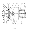
- the jaw device proper consists of a yoke 7 between the wings of which are mounted, laterally pivotally at 10, two jaws 6 whose free edges or jaws 5 are adapted to hang in the lateral grooves 4 of the longitudinal rib 3 of the post 1.
- Each jaw is also provided over the entire height of its inner face with a projecting part 5a adapted to penetrate, in the closed position, in a countersink or flat 3b provided in the corresponding edge of the rib longitudinal 3 at the location of the attachment of the device to the post 1 (as best shown in Figure 3).
- each jaw 6 also has, behind its projecting part 5a, a groove 12 adapted to receive one of the ends of a spring leaf 11 constrained between the two jaws and trapped between the two wings of the yoke 7 which even frame in the maximum open position of these jaws 6.
- Each of the two wings or arm of the yoke 7 is pierced vertically by a housing 8, of rectangular section, in which slides a key 9 guided by a rib or lug 13 internal to this housing 8.
- the key 9 is very specifically profiled to allow the jaws to open when it is partially released upwards from its housing 8 as well as to control their closing when it is engaged in strength in the latter.
- this key has, from its lower end 15, provided with an orifice 16 for a total anti-extraction pin (not shown), at its upper end, provided with a projecting cap 17 preventing the penetration of foreign bodies into the housing 8, a part 18, of triangular section followed by a part 20, of rectangular section with rounded front corners 20a, itself followed by the upper part of the key, of rectangular section, whose width sides 26, 27 are slightly conical in convergence towards the part 18 of triangular section while its length sides, front 24 and rear 25, its parallel to each other over the entire height of the key, the rear side 25 further comprising a rectilinear groove 28, longitudinal and median, in which engage the ribs or pins 13 internal to the respective housings 8 of the two wings of the yoke 7.
- the part 18 of triangular section of the key is provided with a height slightly greater than that of the heels 19 of the jaws 6 and its edge, corresponding to the front face 24, is machined in shape.
- dovetail as best seen in Figure 6, the lateral grooves 18a are configured to receive the free edges of the heels 19 of the jaws and serve as a stop at the end of the opening movement of the latter under the rebound of the spring leaf 11 (see FIG. 2).
- FIG. 2 As best seen in FIG.
- the part 20 of rectangular section comprising rounded corners 20a corresponding to the front face 24 is designed to control, when the key is pressed in, the start of the pivoting movement of the jaws towards their closed or latching position, the rounded corners 20a acting respectively on the ramps 19a provided in a downward slope in the direction of the key on the upper part of the free edges of the heels 19 of the jaws (see FIG. 2 ).
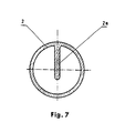
- the sleeve 7a for fixing the yoke 7 of the device intended to be engaged in a tubular element 2 provided with an internal stiffening rib 2a has an upper slot 14 adapted to allow the engagement of this rib 2a and, consequently, serves to put the tubular element 2 in the position where it has the best resistance to bending.
- the tubular element 1, with longitudinal ribs 3 for the attachment of the device is provided with an internal diameter adapted to allow the introduction of a commercial metal tube, of standardized diameter, which can be used as a stiffener and will increase the resistance, both to bending and to compression, of this tubular element 1 which can be made of metal or, for certain uses, of any rigid and insulating plastic material based on polyamide resin , such as the material sold under the name of "reinforced nylon®". All the components of the device itself are also provided made of metal or rigid and insulating plastic of the same type as that constituting the tubular element 1, the tubular element 2, provided in metal, being, in the latter case, sheathed by a coating of insulating plastic material.
Landscapes
- Engineering & Computer Science (AREA)
- Architecture (AREA)
- General Engineering & Computer Science (AREA)
- Mechanical Engineering (AREA)
- Civil Engineering (AREA)
- Structural Engineering (AREA)
- Physics & Mathematics (AREA)
- Electromagnetism (AREA)
- Mutual Connection Of Rods And Tubes (AREA)
Applications Claiming Priority (2)
| Application Number | Priority Date | Filing Date | Title |
|---|---|---|---|
| FR9002326 | 1990-02-26 | ||
| FR9002326A FR2658874B1 (fr) | 1990-02-26 | 1990-02-26 | Dispositif a machoires perfectionne pour l'assemblage d'elements tubulaires. |
Publications (1)
| Publication Number | Publication Date |
|---|---|
| EP0445014A1 true EP0445014A1 (de) | 1991-09-04 |
Family
ID=9394112
Family Applications (1)
| Application Number | Title | Priority Date | Filing Date |
|---|---|---|---|
| EP91400499A Ceased EP0445014A1 (de) | 1990-02-26 | 1991-02-25 | Verbesserte Klemmbackenvorrichtung fÀ¼r die Zusammensetzung von Rohrelementen |
Country Status (2)
| Country | Link |
|---|---|
| EP (1) | EP0445014A1 (de) |
| FR (1) | FR2658874B1 (de) |
Cited By (10)
| Publication number | Priority date | Publication date | Assignee | Title |
|---|---|---|---|---|
| EP0553665A1 (de) * | 1992-01-25 | 1993-08-04 | Peri Gmbh | Traggerüst |
| EP0999368A1 (de) * | 1998-11-06 | 2000-05-10 | Legrand | Befestigungsklammer, insbesondere für Handleuchte |
| WO2002003868A3 (en) * | 2000-07-11 | 2002-04-25 | Dall Vagn-Erik | Gripping devices |
| GB2466768A (en) * | 2008-12-30 | 2010-07-07 | Sgb Services Ltd | A clamp having a pivotal hook and locking element |
| ES2354336A1 (es) * | 2009-05-07 | 2011-03-14 | Inveral S.A. | Pinza para la conexión y fijación en andamios de un elementos de refuerzo a un pilar de apoyo. |
| CN109723060A (zh) * | 2019-02-28 | 2019-05-07 | 兰州理工大学 | 一种手动机械式可回收锚杆及其回收方法 |
| CN111075763A (zh) * | 2019-12-24 | 2020-04-28 | 珠海格力电器股份有限公司 | 对接结构及具有其的风扇 |
| CN113057416A (zh) * | 2021-04-08 | 2021-07-02 | 东莞市乐业五金有限公司 | 钩子 |
| CN116220336A (zh) * | 2023-04-25 | 2023-06-06 | 邢台路桥建设集团有限公司 | 自锁紧耐用脚手架 |
| CN116518127A (zh) * | 2023-06-19 | 2023-08-01 | 宁波方太厨具有限公司 | 阀门与热水器组件 |
Families Citing this family (1)
| Publication number | Priority date | Publication date | Assignee | Title |
|---|---|---|---|---|
| CN111676802B (zh) * | 2018-12-11 | 2021-09-14 | 江山市发发科技有限公司 | 预制桥的桥板桥墩连接结构 |
Citations (5)
| Publication number | Priority date | Publication date | Assignee | Title |
|---|---|---|---|---|
| FR2255438A1 (en) * | 1973-12-21 | 1975-07-18 | Buchner Viviane | Assembly device for shelving frames - has pivotal wedges locking posts in horiz. sections |
| US3952382A (en) * | 1974-07-22 | 1976-04-27 | Einar Vaage | Rapid release hook |
| WO1982002733A1 (en) * | 1981-02-02 | 1982-08-19 | Udo Rose | Steel tube scaffolding |
| GB2154645A (en) * | 1984-02-20 | 1985-09-11 | Saf Const Met | Improvements relating to a set of clamps for a structure of cylindrical rods |
| DE8806128U1 (de) * | 1988-05-09 | 1988-07-28 | Rose, Udo, 4836 Herzebrock | Kupplungsvorrichtung für Riegel von Schalungsgerüsten |
-
1990
- 1990-02-26 FR FR9002326A patent/FR2658874B1/fr not_active Expired - Lifetime
-
1991
- 1991-02-25 EP EP91400499A patent/EP0445014A1/de not_active Ceased
Patent Citations (5)
| Publication number | Priority date | Publication date | Assignee | Title |
|---|---|---|---|---|
| FR2255438A1 (en) * | 1973-12-21 | 1975-07-18 | Buchner Viviane | Assembly device for shelving frames - has pivotal wedges locking posts in horiz. sections |
| US3952382A (en) * | 1974-07-22 | 1976-04-27 | Einar Vaage | Rapid release hook |
| WO1982002733A1 (en) * | 1981-02-02 | 1982-08-19 | Udo Rose | Steel tube scaffolding |
| GB2154645A (en) * | 1984-02-20 | 1985-09-11 | Saf Const Met | Improvements relating to a set of clamps for a structure of cylindrical rods |
| DE8806128U1 (de) * | 1988-05-09 | 1988-07-28 | Rose, Udo, 4836 Herzebrock | Kupplungsvorrichtung für Riegel von Schalungsgerüsten |
Cited By (16)
| Publication number | Priority date | Publication date | Assignee | Title |
|---|---|---|---|---|
| EP0553665A1 (de) * | 1992-01-25 | 1993-08-04 | Peri Gmbh | Traggerüst |
| US5388666A (en) * | 1992-01-25 | 1995-02-14 | Peri Gmbh | Support scaffold |
| EP0694659A3 (de) * | 1992-01-25 | 1996-03-06 | Peri Gmbh | |
| EP0999368A1 (de) * | 1998-11-06 | 2000-05-10 | Legrand | Befestigungsklammer, insbesondere für Handleuchte |
| FR2785649A1 (fr) * | 1998-11-06 | 2000-05-12 | Legrand Sa | Pince de fixation, notamment pour baladeuse |
| US6327756B1 (en) | 1998-11-06 | 2001-12-11 | Legrand | Fixing clamp, especially for inspection lamps |
| WO2002003868A3 (en) * | 2000-07-11 | 2002-04-25 | Dall Vagn-Erik | Gripping devices |
| US7320556B2 (en) | 2000-07-11 | 2008-01-22 | Dall Vagn-Erik | Gripping devices |
| GB2466768A (en) * | 2008-12-30 | 2010-07-07 | Sgb Services Ltd | A clamp having a pivotal hook and locking element |
| GB2466768B (en) * | 2008-12-30 | 2011-01-05 | Sgb Services Ltd | A clamp |
| ES2354336A1 (es) * | 2009-05-07 | 2011-03-14 | Inveral S.A. | Pinza para la conexión y fijación en andamios de un elementos de refuerzo a un pilar de apoyo. |
| CN109723060A (zh) * | 2019-02-28 | 2019-05-07 | 兰州理工大学 | 一种手动机械式可回收锚杆及其回收方法 |
| CN111075763A (zh) * | 2019-12-24 | 2020-04-28 | 珠海格力电器股份有限公司 | 对接结构及具有其的风扇 |
| CN113057416A (zh) * | 2021-04-08 | 2021-07-02 | 东莞市乐业五金有限公司 | 钩子 |
| CN116220336A (zh) * | 2023-04-25 | 2023-06-06 | 邢台路桥建设集团有限公司 | 自锁紧耐用脚手架 |
| CN116518127A (zh) * | 2023-06-19 | 2023-08-01 | 宁波方太厨具有限公司 | 阀门与热水器组件 |
Also Published As
| Publication number | Publication date |
|---|---|
| FR2658874B1 (fr) | 1992-05-15 |
| FR2658874A1 (fr) | 1991-08-30 |
Similar Documents
| Publication | Publication Date | Title |
|---|---|---|
| EP0445014A1 (de) | Verbesserte Klemmbackenvorrichtung fÀ¼r die Zusammensetzung von Rohrelementen | |
| FR2593689A1 (fr) | Chaise d'enfant pliante a deux ou plusieurs positions d'emploi | |
| EP1922224A1 (de) | Sicherheitssitz für baby oder sehr kleines kind zur verwendung auf einem fahrzeugsitz | |
| EP3144199B1 (de) | Vorrichtung zur erhöhung von komfort, insbesondere für ein schienenfahrzeug, umfassend einen herausnehmbaren tisch | |
| EP0277073A2 (de) | Befestigungsvorrichtung für den Rand eines ausgespannten Tuches, insbesondere anwendbar zur Befestigung des unteren Randes eines Zelttuches und mit einer solchen Vorrichtung versehene Schutzhütte | |
| EP2495375B1 (de) | Integrierte wandschalung mit einem mobilen schwenkbarem verbindungselement | |
| FR2662553A1 (fr) | Appareil electrique a rapporter sur un support par simple encliquetage. | |
| BE1024563A1 (fr) | Un kit pour la connexion entre panneaux séparateurs dans les étables ou porcheries | |
| EP1106218B1 (de) | Langlaufski | |
| FR3051506A1 (fr) | Installation de volet roulant comprenant un dispositif de blocage du tablier | |
| EP0715383A1 (de) | Anordnung zur Befestigung eines elektrisches Gerätes an einer Tragschiene | |
| EP0734665B1 (de) | Bettgestell, mit übereinander angeordneten abklappbaren Rahmen, das mit Bodenstützen ausgestattet ist | |
| FR2810929A1 (fr) | Dispositif d'assise pour vehicule | |
| FR2681478A1 (fr) | Armoire, notamment pour appareillages electriques, comportant interieurement une plaque de support a disposer verticalement. | |
| EP2071103B1 (de) | Mechanismus zum Entfalten eines Gestells, insbesondere eines Zeltgestells, und zur Aufrechterhaltung dieses Gestells in entfaltetem Zustand | |
| FR2890407A3 (fr) | Poteau pour cloture a panneaux | |
| EP2386333B1 (de) | Befestigungselement mit einstellbarer Position auf einem Schneegleitbrett | |
| FR2655393A1 (fr) | Dispositif d'assemblage d'equerre entre des elements tubulaires. | |
| FR2627997A1 (fr) | Dispositif de fixation d'une chaussure sur un ski de fond | |
| EP0533556A1 (de) | Verschlusseinrichtung für eine umwendbare Tür, und Schrank mit solcher Einrichtung, für ein Elektrisches Gerät | |
| EP3210822A1 (de) | Vorrichtung zum einhaken eines fahrzeugsitzes ohne drehmoment in der halterung im falle einer kollision | |
| EP1025882A1 (de) | Sicherheitsskibindung-Schuh-Kombination | |
| FR2555235A1 (fr) | Dispositif de blocage d'un organe, en particulier le volet ou la ridelle d'un vehicule a plate-forme | |
| BE507150A (de) | ||
| EP1121960A1 (de) | Skibindung mit abnehmbarer Bremse |
Legal Events
| Date | Code | Title | Description |
|---|---|---|---|
| PUAI | Public reference made under article 153(3) epc to a published international application that has entered the european phase |
Free format text: ORIGINAL CODE: 0009012 |
|
| AK | Designated contracting states |
Kind code of ref document: A1 Designated state(s): DE GB |
|
| 17P | Request for examination filed |
Effective date: 19911107 |
|
| 17Q | First examination report despatched |
Effective date: 19920708 |
|
| STAA | Information on the status of an ep patent application or granted ep patent |
Free format text: STATUS: THE APPLICATION HAS BEEN REFUSED |
|
| 18R | Application refused |
Effective date: 19931007 |