EP0445034A1 - Vorrichtung und Benutzung dieser Vorrichtung in einem Verfahren zum Karten-Auswechseln - Google Patents
Vorrichtung und Benutzung dieser Vorrichtung in einem Verfahren zum Karten-Auswechseln Download PDFInfo
- Publication number
- EP0445034A1 EP0445034A1 EP19910400541 EP91400541A EP0445034A1 EP 0445034 A1 EP0445034 A1 EP 0445034A1 EP 19910400541 EP19910400541 EP 19910400541 EP 91400541 A EP91400541 A EP 91400541A EP 0445034 A1 EP0445034 A1 EP 0445034A1
- Authority
- EP
- European Patent Office
- Prior art keywords
- service
- application
- presentation
- message
- program
- Prior art date
- Legal status (The legal status is an assumption and is not a legal conclusion. Google has not performed a legal analysis and makes no representation as to the accuracy of the status listed.)
- Granted
Links
Images


Classifications
-
- G—PHYSICS
- G06—COMPUTING OR CALCULATING; COUNTING
- G06F—ELECTRIC DIGITAL DATA PROCESSING
- G06F15/00—Digital computers in general; Data processing equipment in general
-
- G—PHYSICS
- G06—COMPUTING OR CALCULATING; COUNTING
- G06F—ELECTRIC DIGITAL DATA PROCESSING
- G06F11/00—Error detection; Error correction; Monitoring
- G06F11/22—Detection or location of defective computer hardware by testing during standby operation or during idle time, e.g. start-up testing
- G06F11/2294—Detection or location of defective computer hardware by testing during standby operation or during idle time, e.g. start-up testing by remote test
-
- G—PHYSICS
- G06—COMPUTING OR CALCULATING; COUNTING
- G06F—ELECTRIC DIGITAL DATA PROCESSING
- G06F11/00—Error detection; Error correction; Monitoring
- G06F11/07—Responding to the occurrence of a fault, e.g. fault tolerance
- G06F11/16—Error detection or correction of the data by redundancy in hardware
- G06F11/20—Error detection or correction of the data by redundancy in hardware using active fault-masking, e.g. by switching out faulty elements or by switching in spare elements
-
- G—PHYSICS
- G06—COMPUTING OR CALCULATING; COUNTING
- G06F—ELECTRIC DIGITAL DATA PROCESSING
- G06F11/00—Error detection; Error correction; Monitoring
- G06F11/22—Detection or location of defective computer hardware by testing during standby operation or during idle time, e.g. start-up testing
- G06F11/26—Functional testing
- G06F11/273—Tester hardware, i.e. output processing circuits
- G06F11/2736—Tester hardware, i.e. output processing circuits using a dedicated service processor for test
-
- G—PHYSICS
- G06—COMPUTING OR CALCULATING; COUNTING
- G06F—ELECTRIC DIGITAL DATA PROCESSING
- G06F11/00—Error detection; Error correction; Monitoring
- G06F11/22—Detection or location of defective computer hardware by testing during standby operation or during idle time, e.g. start-up testing
-
- G—PHYSICS
- G06—COMPUTING OR CALCULATING; COUNTING
- G06F—ELECTRIC DIGITAL DATA PROCESSING
- G06F11/00—Error detection; Error correction; Monitoring
- G06F11/30—Monitoring
- G06F11/32—Monitoring with visual or acoustical indication of the functioning of the machine
Definitions
- the present invention relates to a system architecture and the use of this architecture in a card replacement method.
- System architectures are known comprising service processors and a reserve processor each specific to the system.
- this remote maintenance or these programs operated remotely are carried out with means having an unsophisticated ergonomics and requiring, on the part of the operator, specific knowledge of the system.
- a first object of the invention is therefore to propose an architecture allowing remote use of a service processor of a central system, this use being made with good ergonomics.
- the architecture making it possible to control an application remotely, comprises a first service processor connected by a network and a channel maintenance unit (40) connected to a central system (4), said service processor (1) being connected by a service console switch (30), to an RMS maintenance service console (6 ), and to a remote service console RSC (5), characterized in that each service processor and each console comprises, in addition to operating system programs, a supervisor program and at least one service broken down into two applications, l 'a "body” composed of the program algorithm, the other "presentation" comprising the operator interface allowing a window type display with a menu bar.
- Another object of the invention is to allow the use of the standby processor to present a service which is executed by the holding processor.
- the standby service processor comprises means for running the presentation application corresponding to a service, and means for communicating with the holding service processor comprising the means for running at the same time l the trunk application of a service, the presentation of which is made on the standby processor, and the trunk application, as well as the presentation of a second service, the presentation of which is made on itself.
- each service processor or console comprises a supervisor program managing the instance numbers of the services, and ensuring the starting of the services.
- each service processor comprises means for processing communications with the other service processor.
- each console comprises means for processing communications by the service console switch with one of the service processors.
- the application presentation program comprises windows generated as a function of the application and stored in a memory, and a message communication module (183) linked to the application presentation program and containing primitives intended to receive messages containing the address of the memory block in which the message is stored or to send messages containing the address of the memory block of the body program containing the command corresponding to the response provided by the operator in received message.
- the application body program comprises a message communication module (173) linked to the application body program and containing primitives intended to send messages containing the address of the memory block containing the message, and to receive messages containing the address of the memory block of the body program in which the response supplied by the operator is stored.
- Another object of the invention is to propose a use of the previous architecture in a card replacement process, comprising a presentation application consisting in displaying in a dialog box the identity of a group of elements to be selected ; selecting the identity of the group of elements by validating the identity with the mouse or the keyboard; selecting from the group one of the elements by highlighting this element; to confirm the selection by clicking with the mouse on the block containing the message "OK".
- the application of the presentation also consists in displaying in a dialog box a message indicating that the location is occupied, and that the system will try to copy its content, and a question asking for confirmation or the 'stop service; to select the confirmation or the stop of the service, in coming to click a "Yes" or "No” block.
- the method consists in displaying in a dialog box the group of elements from which a second element will be selected by bringing a highlighting on this element; to validate the selection by clicking on the block containing the message "OK".
- the method consists in requesting confirmation of the request to insert a new card; to indicate in a dialog box that the operator can make the change, and after this to request confirmation or invalidation; to confirm or deny the location by clicking on a location indicating that the second location is full, respectively empty.
- the method consists in displaying the execution of the test on the card put in place; to display the success of copying the information contained in the first element; and an authorization message to withdraw the card from the first location; to ask the operator for confirmation or cancellation of the withdrawal by clicking on an area indicating that the first location is empty, respectively occupied.
- FIG. 20 represents a variant representation of one of the stages of the presentation program for replacing a card corresponding to FIGS. 9 or 12.
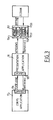
- the architecture of the system is constituted, as shown in FIG. 1, by a service processor holding (1), connected by an interface software (10) MSH (Maintenance Station Handler) with a line for processing maintenance of the telecommunication stations (12) forming a STARLAN type network.
- This line (12) is connected to a clock and maintenance unit (40) which ensures communications between the service processor (1), a second standby service processor, via a second line ( 22), and a central system (41).
- the maintenance and clock unit (40) of a central subsystem (4) also communicates by a line (43) with a set of maintenance processors (42).
- the service processor holding (1) and the backup service processor (2) also communicate via a remote line management interface (11) RLH (Remote Line Handler), and respectively (21), with a service console switch (3), which makes it possible, via a circuit (30), and an appropriate switching matrix, to activate communication each of the service processors with the telecommunication network of a given country, and through this network with a station (5) constituting a remote service console communicating with this network (52) by means of software 'RSC interface (50).
- each of the service processors can be put in communication, through the network (52), with a remote maintenance station (6) communicating with the network (52) by an RMS interface software (51).
- Lines (23) and (13) connected to the service console switch by interface software (21) and (11) have bit rates of 4,800 baud, while lines (12) and (22) form the network STARLAN with the clock and maintenance unit (40) have speeds of the order of megabits per second.
- the maintenance processors (42) are connected to sets of input / output units for the central system.
- FIG. 2 represents the software environment allowing the service processors (1, 2) to communicate via the STARLAN network with the maintenance unit (40).
- the service processor holding comprises in addition to the MSH software (10) and an operating system comprising the operating system of the MS-DOS disk, multitasking window software such as WINDOWS, and a part of software that the 'will be described later.
- the service processor holding also includes NETBIOS communication software (100) communicating through a network card STARLAN type (14) and a hardware element (101) constituting a gateway, through the line (12) of the STARLAN network, to a second gateway (400), a management circuit (401), NETBIOS interface software (402) and software for interfacing with the service processor (403).
- the standby service processor (2) will also have the same elements, but with the digit 2 as a reference for the tens or hundreds digit.
- Each service processor additionally includes in its operating system (15, 25) a body program for a given application (17, 27, fig. 1) and a program presenting the application (18, 28, fig. 1 ).
- the remote consoles (5, 6) can be constituted, as for the service processors, of microcomputers having in addition to the keyboard of a mouse, and of an operating system (65, 55) constituted also as for the service processors of the MS-DOS disk operating system, a WINDOWS multi-window software, and an SPV supervisor software, whose role is to launch the presentations in the console (s).
- An LPXMS module makes it possible to store in the LOG and LOGM files of the hard disk respectively the incident messages and all the dialogues of all the services.
- the supervisor of the service processor holding also knows by RLH, the state of connection or disconnection of the consoles to control the console switch (30) accordingly and configure the presentations, as we will see later.
- the maintenance and clock unit makes it possible to launch the second service processor in the event of failure of the first, and the SPV supervisor installs in the latter the same applications.
- These remote stations (5, 6) also include presentation software (58, 68) corresponding to the presentation software of the body programs of an application running on a service processor (1), respectively (2).
- FIG. 3 represents the principle of the architecture necessary for the implementation of the invention in which the body program (17) of a given application, running for example on the service processor holding, exchanging lines of text and acknowledgment or response messages with the presentation program (18) of the application.
- These exchanges of messages and lines of text are carried out by means of library management modules for messages LBXMS (171) and LPXMS (183) which are linked respectively to the body of the application and to the presentation of the application.
- the presentation program of the application exchanges with the WINDOWS software (150), the primitives necessary for the management of tasks and the display of windows.
- the presentation application will have been developed using the WINDOWS (150) program which can be seen as a set of four components.
- a first kernel component (Kernel) (151) ensuring the management of tasks, allocations of memory, TIMER function and dynamic links.
- a second user element (152) used to manage the windows and create them.
- a third GDI element (153) making it possible to perform the graphic functions for drawing purposes, and a fourth COM element (154) ensuring the communication functions asynchronously, for example by means of a DDE protocol (dynamic exchange which is a data exchange protocol between applications and allows communication between applications.
- DDE protocol dynamic exchange which is a data exchange protocol between applications and allows communication between applications.
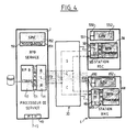
- FIG. 4 represents the operation of the architecture in the case of a service processor holding (1) connected via a service console switch (30) to the remote maintenance console (6) and to the remote service console (5) consisting of a microcomputer.
- This microcomputer like the service processor (1), comprises a mouse and an operating system (550, 551, 552) constituted respectively by the software MS-DOS, WINDOWS and a supervisor SPV.
- the operating system is constituted in the same way by the elements (650, 651, 652).
- An RSC interface (50) provides the interface between the telecommunication lines and the microcomputer (5), and through these telecommunication lines, to the service processor which is itself interfaced with the communication lines by the RLH interface (11).
- the maintenance station includes an RMS interface (60) having the same functions as the RSC interface.
- This RSC interface communicates by a message library module (583) linked to the presentation of the application (58) constituted by a RPB card replacement application (replace board).
- the card replacement application body (17) rotates on the holding service processor and is linked to a message library allowing communication with the RLH interface (11).
- the service console switch (30) makes it possible, thanks to a switching matrix and to the information provided by the RLH interface of the holding processor (1), to direct messages coming from the service processor to the two consoles, if these two consoles are connected, to route all the messages sent by the remote service console (5) to the service processor (1) and the maintenance console, if the latter is connected, and to route all the messages issued by the maintenance console to the service processor.
- This is enabled by the fact that RLH, as the consoles are connected, establishes a dialogue with the respective RSC or RMS interface, and notifies the supervisor program (152) the state of connection or disconnection of the consoles from the network. This table is then used to establish communications through the console switch (30).
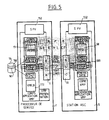
- FIG. 5 represents the operation of the architecture described in the case where the service processor (1) is in communication with a remote console (5).
- This remote console (5) used for presenting a RPB application (58), thanks to the XMESS library module (583) and to the RSC interface (50) which communicates via the network with the RLH interface (11 ) of the service processor.
- the service processor executes the body program of the application (17), and the supervisor (152) stores, on a disk (16), in a LOG file (160) and in a LOGM file (161) , respectively the incident messages and all the dialogs of all the services running in the service processor.
- the RLH interface (11) sees the remote stations through the service console switch (30) and conducts only one data communication line connecting RLH and SCC.
- the two data communication lines, connecting the service processor with the RMS and RSC stations, are conducted by SCC.
- the service processor (1) can, for example, execute another application called VMP, and thanks to the presentation program of this VMP application, present this application on its monitor, while the second RPB application will be presented on the monitor of the RSC station. At the same time, a dialog copy of the VMP application will be available on the RSC station.
- VMP another application
- the presentation program of this VMP application present this application on its monitor
- the second RPB application will be presented on the monitor of the RSC station.
- a dialog copy of the VMP application will be available on the RSC station.
- FIG. 6 represents another advantage of the proposed architecture which makes it possible, for example, to use the standby service processor (2) to make the presentation of an application which is running on the holding service processor (1).
- This has the advantage of allowing use of the standby service processor which, given the increase in the reliability of the hardware, becomes less and less used in its role as standby service processor, and can thus be used. as an additional console for presenting an application.
- the service processor (2) executes the presentation of the RPB application (27), while the body of the RPB application is executed by the service processor holding (1).
- the service processors (1) and (2) communicate with each other via the MSH interfaces (10, 20) and the STARLAN network, as shown in FIG. 2.
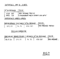
- Figure 7 shows the format of the messages.
- the first type of format corresponds to the messages exchanged between the body of an application and the XMESS library module.
- the format consists of a message number which can be VSH 001, or RPB 120 in the case of the card replacement application, followed by the message text which can be "my prefixed message", where in the case of the card replacement application, "the required space contains a card”.
- the message When the messages are exchanged between the XMESS library modules of two remote interfaces, the message consists of the service name which can be SYC 01, of the instance, followed by the message number and the text as seen above.
- the archived messages shown on the last line, precede the format of the XMESS interface message with the date and time.
- Figures 8 to 16 show an example of an application whose body and presentation can be separated according to the principle of the invention.
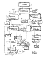
- FIG. 8 The algorithm for the progress of the body program is represented by FIG. 8, while FIGS. 10 to 15 represent the results produced by the execution of the presentation application.
- the first step is to launch the RPB service, indicated by the reference (900).
- This step consists first of making the SPV supervisor service appear in the window to come and select from the menu of different services the replacement of the RPB card, and launch it by clicking on its name with the mouse.
- the first question posed by RPB is to provide it with the identifier of the physical location where the manipulation takes place.
- This step is indicated by step (901) on the flow chart.
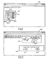
- This step is reflected in the card replacement presentation program by the appearance of a window (9010, fig. 9) inside which is represented a dialog box (9011) comprising a first assembly (9012) consisting of a box of three radio buttons, corresponding to each of the types of elements likely to be replaced.
- This dialog box includes a list box (9013) which, once a type of element has been selected, for example the type of memory units by clicking on the radio button opposite, brings up in the list box, the list of the different elements of the memory unit that can be selected.
- This list appears by a flow system well known to WINDOWS users. Once the type of unit and the identity of this unit selected, the choice is validated by clicking with the mouse on a validation block (9014).
- the body program proceeds to the location requisition step to allow the desired manipulation. If the physical unit present in the chosen location is unavailable, the body program causes the presentation program to display this information and then stops in step (907). The display of this unavailability information is reflected between the body program and the presentation by the exchange of a message referenced "RPB 120" indicating "the required location contains a map at this time”.
- This message processed by the presentation program, causes the appearance of the window (9050, fig. 10) in which a dialog box (9051) contains a figurative element and the sentence of the message, as well as a validation block ( 9052) which, after being clicked with the mouse, allows you to acknowledge receipt of the message, as shown in Figure 17.
- a second dialog box in this window asks the operator if he wants to abort this action, or continue it.
- This second box contains the block (9071) which corresponds to the interruption of the action and diverts the body program to the "end" stage (911, fig. 8).
- a second block (9072, fig. 10) triggers, by a response message sent to the body program, the continuation of the manipulation by the manipulation preparation stage (909, fig. 8) of the body program.
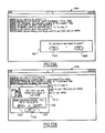
- the RPB body program informs the presentation of the success of the requisition by a message and prepares the manipulation for step ( 909) by indicating to the operator that the system is trying to copy the unused card.
- This is represented in figure 11, by the window (9090) which includes a dialog box (9091), inside which appears a message "the memory card is allocated, we are trying to copy it", and a block validation (9092).
- This window (9090) also includes a second dialog box (9110) in which a first block makes it possible to interrupt the action, as shown in step (911) of FIG. 9, and a second block (9112) allows to continue the action by going to step (913) of the flow diagram of FIG. 9.
- the step of determining the location (901) can optionally be followed by a complementary step information (904), for example in the case where one wishes to copy a memory card to a location on the card intended for copying.
- This step triggers in the presentation program, the display of the window (9040) which includes a dialog box (9041) of constitution identical to the dialog box (9011).
- step (904) continues with a step in which it is specified whether the operator intends to use a new card, or a card in place for copying.
- These steps trigger in the presentation program, the display of a window (9060, fig. 13A) comprising a dialog box (9061 ) with the question "Do you have a new card to insert?", and a "Yes" answer block (9062) indicating that there is a new card, and a "No” answer block (9080) indicating that we plan to use an existing card.
- the blocks are, in a known manner, validated by the mouse of the service processor or of the remote station used to run the presentation.
- RPB checks that the designated unit is available, and if so requires it by step (912, fig. 9) which will be explained below. If the operator wishes to use a new card, RPB ensures that the designated location is empty, and if so, requires it during the step (909) of preparation for handling.
- the body program receives the green light from the central unit, and indicates in the "action” step (913) that the manipulation can be carried out.
- This “action” step (913) triggers, at the level of the PRPB presentation program, the display of the window (9130, fig. 13B), which includes a dialog box (9131) including the message of authorization of insertion of the map in the defined location, and including a second dialog box (9132) asking to indicate, once the operation is finished, whether the location is full or empty by validating one of the two buttons respectively radio (9150) or (9170). Then, the operation is validated by clicking with the mouse, the block (9133).
- step (921) the body program continues with step (921) during which a test of the card in place is carried out before authorizing its final insertion into the installation. These tests will be carried out by the "DGM" service which will be launched automatically by RPB, and RPB will start waiting for the result.
- the card replacement presentation program informs you of the test result. This is done by the message RPB (111) "All is well, the initialization of the new card is successful" (All right, the new board init is successful). In this case, the service ends at step (907).
- the RPB body program offers you at step (923) a new card exchange, and if you accept it, the program starts again at step (909).
- the RPB body program returns us to step (912) for testing and initialization.
- the memory card intended for copying having been inserted, the RPB body program will attempt to initialize it. This is indicated by the RPB presentation program by displaying the window (9120) in which a dialog box (9121) displays the message "Test in progress", as well as a validation block (9122) allowing to acknowledge receipt of the message sent by the RPB body program.
- RPB checks that it is compatible with the faulty card which it is supposed to take the place of, and in the affirmative case, RPB performs the copying and exchange, and signals that it is necessary to remove the 'old card which it recalls the identifier.
- the initialization step is represented in the window (9123, fig. 15.A) by the dialog box (9124), which contains the message "Everything is fine, the copy is successful", and a validation block ( 9125) to acknowledge receipt of the message.
- the RPB body sends a second message informing the operator that it can now remove the card.
- This message is displayed in a dialog box (9126) and also includes a validation block (9127) making it possible to acknowledge receipt of said message.
- RPB indicates that it must be removed and recalls its identifier.
- the removal step (914) brings up the window (9140, fig. 15B), which contains a dialog box (9141) including a drawing (9142) and a message (91410) indicating that the card located must be removed in location HM04.
- This dialog box also includes a box of radio buttons (9143) asking to indicate when the operation is finished and allowing the radio button (91430) to indicate that the location is full, and by the button radio (9431) to indicate that the space is empty, and that by Consequently, the card has been successfully removed.
- This dialog window is validated by a validation block (9144) allowing to validate the responses clicked by the mouse.
- step (916) the program causes, in step (916), the message shown in the dialog box (9160, fig. 16) to be displayed, indicating that the copying has been carried out normally and that there is no there is no particular problem.
- the operator acknowledges receipt of the message by validating the block (9161).
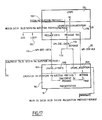
- FIG. 17 represents the exchanges between the body of an application (170) and the presentation (184) of this application, in the case of a message requiring no response and for a presentation implemented on the same entity.
- the application body program (170) is linked (linked) to a message exchange library module (171).
- a message exchange library module (171) When during the course of the body program (170), the latter arrives at a message to be sent or question to be sent step, represented by the reference (1701), corresponding in the case shown to a question with a prefix, the body program (170) calls in the library module (171) a message sending and receiving primitive (1710), sending / receiving primitive (send / receive).
- This primitive stores the message to be sent in a buffer of the service processor and sends a DDE (Dynamic Data Exchange) message for dynamic data exchange (172).
- DDE Dynamic Data Exchange
- the XMS message exchange program writes the message to the LOGM hard disk file (1711) which contains the dialog of all the services (1711).
- the message (172) for dynamic data exchange sent by the service processor in which the body of the application turns to the presentation software running on the same processor, contains the address of the memory block which contains the message or the question.
- the presentation application and its message exchange module (183) is in the waiting state, represented by LPXMS_WAIT from step (1830).
- the presentation application (184) receives a VM_DDE_DATA (172) message, then this application will read the message at the address indicated. Once this reading has been carried out, the application processes the message by going to look in the presentation program of the application, the elements allowing to carry out the required displays and to receive the answers required by the question.
- this response (1840) is delivered to a reception primitive (1831) (receiver) of the message exchange library module (183).
- This primitive makes it possible to send a first dynamic message (175) of acknowledgment of receipt of the question, and after formatting the response, to send a message (176) containing the memory address to which the response has been stored, to allow the primitive (1710) to process the response by reading the response contained at the address indicated by the message (176).
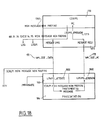
- FIG. 18 represents the exchanges between the body of an application (170) and the presentation (184) of this application, in the case of a message requiring no response and for a presentation implemented on the same entity, such as for example the service processor holding.
- the message (1801) calls on a sending primitive (1810), which after formatting and preparing the message with the necessary headers, sends a DDE message (182) consisting of the address to which the prepared message is stored.
- the message exchange module (183) attached to the presentation when it receives the DDE message, will read the message at the address indicated and launch the message processing operation in the presentation program .
- This message processing operation consists in fetching at the appropriate addresses, the data corresponding to the displays to be carried out, so as to allow the display of a window such as that of FIG. 14.
- the presentation module (184) activates the primitive (1832) which consists in sending an acknowledgment to the attention of the body of the application (180).
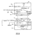
- the operating principle is the same as that of FIG. 18, with the only difference that the dynamic data exchange message (192) is sent to the attention of the RLH program.
- This RLH (11) program interfaces with a second RSC (50) or RMS (60) program located on the remote console.
- the RSC program (50) notifies, upon receipt of a message by the telecommunication line, the XMS application (183) for processing message of the presentation which is in the waiting state, and transmits this message to the presentation application (184).
- the architecture thus produced not only makes it possible to have a second service processor or a remote station execute the presentation of an application whose body program is executed remotely by a first service processor, but also to improve the Human Machine Interface.
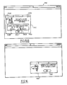
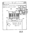
- the RPB card replacement presentation program comprises a first step, represented in FIG. 20, consisting in displaying in a window (2010) a box (20100) showing the various constituent elements of the system: the service processor AUSP (20101), the system cabinet (20102) containing the central subsystem (20104), the power supply (20103) and the ventilation assembly (20103).
- the presentation program brings up a second box (2011), presenting for example in the case of the selection of the central subsystem (20104), all of the cards (20114) available on the front panel and all of the cards (20115) available on the rear panel of the cabinet.
- the program displays a message box (2012) asking to select the location in which you want to replace the card.
- Figure 12 can also be replaced by a presentation of the type of Figure 20, with a message in the message box asking to indicate which location to use to copy the memory.
Landscapes
- Engineering & Computer Science (AREA)
- Theoretical Computer Science (AREA)
- General Engineering & Computer Science (AREA)
- General Physics & Mathematics (AREA)
- Physics & Mathematics (AREA)
- Quality & Reliability (AREA)
- Computer Hardware Design (AREA)
- Information Transfer Between Computers (AREA)
- Computer And Data Communications (AREA)
- Auxiliary Devices For And Details Of Packaging Control (AREA)
- Stored Programmes (AREA)
- Digital Computer Display Output (AREA)
- Exchange Systems With Centralized Control (AREA)
- Multi Processors (AREA)
- Input From Keyboards Or The Like (AREA)
Applications Claiming Priority (2)
| Application Number | Priority Date | Filing Date | Title |
|---|---|---|---|
| FR9002517A FR2658934B1 (fr) | 1990-02-28 | 1990-02-28 | Architecture de systeme et utilisation de cette architecture dans un procede de remplacement de cartes. |
| FR9002517 | 1990-02-28 |
Publications (2)
| Publication Number | Publication Date |
|---|---|
| EP0445034A1 true EP0445034A1 (de) | 1991-09-04 |
| EP0445034B1 EP0445034B1 (de) | 1997-05-02 |
Family
ID=9394236
Family Applications (1)
| Application Number | Title | Priority Date | Filing Date |
|---|---|---|---|
| EP91400541A Expired - Lifetime EP0445034B1 (de) | 1990-02-28 | 1991-02-27 | Vorrichtung und Benutzung dieser Vorrichtung in einem Verfahren zum Karten-Auswechseln |
Country Status (8)
| Country | Link |
|---|---|
| US (2) | US5396629A (de) |
| EP (1) | EP0445034B1 (de) |
| JP (1) | JPH0743685B2 (de) |
| KR (1) | KR940009380B1 (de) |
| AT (1) | ATE152531T1 (de) |
| DE (1) | DE69125879T2 (de) |
| ES (1) | ES2103789T3 (de) |
| FR (1) | FR2658934B1 (de) |
Cited By (1)
| Publication number | Priority date | Publication date | Assignee | Title |
|---|---|---|---|---|
| EP0470880B1 (de) * | 1990-08-09 | 1996-10-30 | Bull S.A. | Vorrichtung zum dynamischen Dienstprozessorwechsel |
Families Citing this family (15)
| Publication number | Priority date | Publication date | Assignee | Title |
|---|---|---|---|---|
| US5774642A (en) * | 1990-08-09 | 1998-06-30 | Bull S.A. | Architecture for dynamic service processor exchange providing multitasking environment where multiple processors have access to a system configuration table |
| US5692129B1 (en) * | 1995-07-07 | 1999-08-17 | Novell Inc | Managing application programs in a computer network by using a database of application objects |
| US6047312A (en) * | 1995-07-07 | 2000-04-04 | Novell, Inc. | System for replicating and associating file types with application programs among plurality of partitions in a server |
| US5911120A (en) | 1995-09-08 | 1999-06-08 | At&T Wireless Services | Wireless communication system having mobile stations establish a communication link through the base station without using a landline or regional cellular network and without a call in progress |
| US5675629A (en) | 1995-09-08 | 1997-10-07 | At&T | Cordless cellular system base station |
| US6385682B1 (en) * | 1996-10-18 | 2002-05-07 | Compaq Information Technologies, Group, L.P. | System and method for controlling remote console functionality assist logic |
| US6742066B2 (en) * | 1999-05-17 | 2004-05-25 | Hewlett-Packard Development Company, L.P. | System and method for controlling remote console functionality assist logic |
| US6728764B1 (en) * | 2000-11-08 | 2004-04-27 | Unisys Corporation | Method and apparatus for operating a data processing system |
| US7293075B2 (en) * | 2001-04-12 | 2007-11-06 | Unisys Corporation | Method and apparatus for operating a data processing system using multiple console views |
| US7379393B2 (en) * | 2002-10-07 | 2008-05-27 | Michael Morykwas | Timer device for use in an audio/visual presentation |
| US7403204B2 (en) * | 2004-08-23 | 2008-07-22 | Hewlett-Packard Development Company, L.P. | Method and apparatus for managing changes in a virtual screen buffer |
| KR101083848B1 (ko) | 2005-06-25 | 2011-11-15 | 인텔 코오퍼레이션 | 서비스 호출을 지원하는 장치, 시스템 및 방법 |
| JP2008544611A (ja) * | 2005-06-25 | 2008-12-04 | インテル・コーポレーション | 入力/出力モジュールのレガシセンサおよび遠隔制御センサを使用してサービス呼び出しをサポートする装置、システム、および方法 |
| US8938713B2 (en) * | 2012-02-09 | 2015-01-20 | International Business Machines Corporation | Developing a collective operation for execution in a parallel computer |
| US11689605B2 (en) * | 2020-04-16 | 2023-06-27 | National Technology & Engineering Solutions Of Sandia, Llc | In-network compute assistance |
Citations (2)
| Publication number | Priority date | Publication date | Assignee | Title |
|---|---|---|---|---|
| EP0031782A1 (de) * | 1979-12-31 | 1981-07-08 | COMPAGNIE INTERNATIONALE POUR L'INFORMATIQUE CII - HONEYWELL BULL (dite CII-HB) | Vorrichtung, die die Steuerung eines Informationsverarbeitungssystems von einem lokalen Pult und von einem entferten Pult ermöglicht |
| EP0348293A1 (de) * | 1988-06-22 | 1989-12-27 | Bull S.A. | Verfahren zur Generierung von Dialogausschnitten, sichtbar auf einem Bildschirm eines Rechners und Gerät zur Durchführung dieses Verfahrens |
Family Cites Families (9)
| Publication number | Priority date | Publication date | Assignee | Title |
|---|---|---|---|---|
| US4695946A (en) * | 1984-10-25 | 1987-09-22 | Unisys Corporation | Maintenance subsystem for computer network including power control and remote diagnostic center |
| US4750136A (en) * | 1986-01-10 | 1988-06-07 | American Telephone And Telegraph, At&T Information Systems Inc. | Communication system having automatic circuit board initialization capability |
| US4803623A (en) * | 1986-10-31 | 1989-02-07 | Honeywell Bull Inc. | Universal peripheral controller self-configuring bootloadable ramware |
| US5062040A (en) * | 1986-12-22 | 1991-10-29 | At&T Bell Laboratories | Handling of notification of asynchronous events by user and stub processes of a distributed process executing on a plurality of processors of a multi-processor system |
| EP0306244B1 (de) * | 1987-09-04 | 1995-06-21 | Digital Equipment Corporation | Fehlertolerantes Rechnersystem mit Fehler-Eingrenzung |
| US5214756A (en) * | 1989-03-10 | 1993-05-25 | International Business Machines Corporation | Direct manipulation of icons via conversational linking |
| US5163833A (en) * | 1989-04-14 | 1992-11-17 | Digital Communications Associates, Inc. | Dual personal computer architecture peripheral adapter board |
| US5075847A (en) * | 1989-05-26 | 1991-12-24 | Hewlett-Packard Company | Method and apparatus for computer program encapsulation |
| US5276833A (en) * | 1990-07-02 | 1994-01-04 | Chips And Technologies, Inc. | Data cache management system with test mode using index registers and CAS disable and posted write disable |
-
1990
- 1990-02-28 FR FR9002517A patent/FR2658934B1/fr not_active Expired - Lifetime
-
1991
- 1991-02-27 AT AT91400541T patent/ATE152531T1/de not_active IP Right Cessation
- 1991-02-27 US US07/661,048 patent/US5396629A/en not_active Expired - Lifetime
- 1991-02-27 DE DE69125879T patent/DE69125879T2/de not_active Expired - Fee Related
- 1991-02-27 EP EP91400541A patent/EP0445034B1/de not_active Expired - Lifetime
- 1991-02-27 ES ES91400541T patent/ES2103789T3/es not_active Expired - Lifetime
- 1991-02-28 KR KR1019910003446A patent/KR940009380B1/ko not_active Expired - Fee Related
- 1991-02-28 JP JP3119621A patent/JPH0743685B2/ja not_active Expired - Fee Related
-
1994
- 1994-01-28 US US08/169,399 patent/US5592676A/en not_active Expired - Lifetime
Patent Citations (2)
| Publication number | Priority date | Publication date | Assignee | Title |
|---|---|---|---|---|
| EP0031782A1 (de) * | 1979-12-31 | 1981-07-08 | COMPAGNIE INTERNATIONALE POUR L'INFORMATIQUE CII - HONEYWELL BULL (dite CII-HB) | Vorrichtung, die die Steuerung eines Informationsverarbeitungssystems von einem lokalen Pult und von einem entferten Pult ermöglicht |
| EP0348293A1 (de) * | 1988-06-22 | 1989-12-27 | Bull S.A. | Verfahren zur Generierung von Dialogausschnitten, sichtbar auf einem Bildschirm eines Rechners und Gerät zur Durchführung dieses Verfahrens |
Non-Patent Citations (5)
| Title |
|---|
| ELECTRONIQUE INDUSTRIELLE no. 54, juin 1983, PARIS FR pages 43 - 47; G. Quero: "L'automatisation de la maintenance électronique " * |
| HEWLETT-PACKARD JOURNAL. vol. 38, no. 3, mars 1987, PALO ALTO US pages 21 - 28; G.F. Buchanan et al.: "A Distributed Terminal Controller for HP Precision Architecture Computers Running the MPE XL Operating System" * |
| ICL TECHNICAL JOURNAL. vol. 6, no. 1, mai 1988, OXFORD GB pages 2 - 16; R. Allison: "ICL Series 39 Support Process" * |
| IEEE SPECTRUM. vol. 21, no. 2, février 1984, NEW YORK US pages 36 - 42; T.-S. Liu: "Maintenance processors for mainframe computers" * |
| IEEE TRANSACTIONS ON NUCLEAR SCIENCE. vol. 36, no. 1, février 1989, NEW YORK US pages 756 - 759; R.C. Agostini et al.: "PASHA-An approach to computer-aided hardware debugging" * |
Cited By (1)
| Publication number | Priority date | Publication date | Assignee | Title |
|---|---|---|---|---|
| EP0470880B1 (de) * | 1990-08-09 | 1996-10-30 | Bull S.A. | Vorrichtung zum dynamischen Dienstprozessorwechsel |
Also Published As
| Publication number | Publication date |
|---|---|
| DE69125879D1 (de) | 1997-06-05 |
| JPH064442A (ja) | 1994-01-14 |
| FR2658934A1 (fr) | 1991-08-30 |
| KR940009380B1 (ko) | 1994-10-07 |
| ES2103789T3 (es) | 1997-10-01 |
| ATE152531T1 (de) | 1997-05-15 |
| EP0445034B1 (de) | 1997-05-02 |
| DE69125879T2 (de) | 1997-08-14 |
| US5592676A (en) | 1997-01-07 |
| KR920000036A (ko) | 1992-01-10 |
| US5396629A (en) | 1995-03-07 |
| JPH0743685B2 (ja) | 1995-05-15 |
| FR2658934B1 (fr) | 1992-04-30 |
Similar Documents
| Publication | Publication Date | Title |
|---|---|---|
| EP0445034B1 (de) | Vorrichtung und Benutzung dieser Vorrichtung in einem Verfahren zum Karten-Auswechseln | |
| EP0615196B1 (de) | Kommunikationvorrichtung zwischen mindestens einem Kunden und mindestens einem Anbieter, Anwendung der Vorrichtung | |
| EP0574302B1 (de) | Vorrichtung zum Entwurf von Informationskontrollnetzen für Prozessmodellierung | |
| FR2646254A1 (fr) | Dispositif de commande programmable | |
| EP0843259A1 (de) | System zur Verwaltung und Bearbeitung von verteilten Objekttransaktionen und Verfahren dafür | |
| EP0793171A1 (de) | System zur Konfiguration von vorkonfigurierten Programmen auf vernetzten offenen Systemen in einer verteilten Umgebung und Verfahren zur Durchführung dieses Systems | |
| US20030084198A1 (en) | Method and apparatus for managing data services in a distributed computer system | |
| US6567844B2 (en) | Coordinative work environment construction system, method and medium therefor | |
| FR2760307A1 (fr) | Configurateur de commutateur telephonique, et procedes pour sa mise en oeuvre | |
| FR2645989A1 (fr) | Coupleur multifonctions entre une unite centrale d'ordinateur et les differents organes peripheriques de ce dernier | |
| FR2693009A1 (fr) | Interface utilisateur pour système de traitement transactionnel. | |
| WO1999025105A1 (fr) | Dispositif de tele-ecriture | |
| EP0182678B1 (de) | Fernverarbeitungsterminal mit externen Anschlüssen | |
| EP0969625B1 (de) | Kommunikationsagent zwischen einem Verwalter und mindestens einem Betriebsmittel eines Rechnersystems | |
| FR2572235A1 (fr) | Procede et dispositif d'acquisition, de memorisation et de transmission de donnees specialisees relatives notamment a l'enregistrement des emissions, entre un appareil de type magnetoscope et un centre de traitement | |
| EP0575237B1 (de) | Anordnung zur Datenübertragung zwischen einem Computer-Bus und einem Massenspeicher | |
| EP0470880B1 (de) | Vorrichtung zum dynamischen Dienstprozessorwechsel | |
| CA2102537C (fr) | Outil de simulation d'un code de reseau | |
| EP0531177B1 (de) | Verfahren und Vorrichtung zur Fehlererkennung und Reparatur eines Datenverarbeitungssystems | |
| FR2604003A1 (fr) | Systeme d'interconnexion d'ordinateurs identiques ou compatibles | |
| EP0454526A1 (de) | Symmetrische enggekoppelte Mehrprozessormaschine | |
| EP1422867A1 (de) | System und Verfahren zum Internetzugang | |
| FR2723225A1 (fr) | Procede de travail cooperatif entre deux ordinateurs | |
| FR2683108A1 (fr) | Procede de communication reliant un nombre limite ou non limite de sites en une liaison interactive reelle ou virtuelle. | |
| EP1493083A2 (de) | Umkonfigurierbares steuersystem auf der basis einer hardwareimplementierung von petri-graphen |
Legal Events
| Date | Code | Title | Description |
|---|---|---|---|
| PUAI | Public reference made under article 153(3) epc to a published international application that has entered the european phase |
Free format text: ORIGINAL CODE: 0009012 |
|
| AK | Designated contracting states |
Kind code of ref document: A1 Designated state(s): AT BE CH DE DK ES FR GB GR IT LI LU NL SE |
|
| 17P | Request for examination filed |
Effective date: 19910924 |
|
| RAP3 | Party data changed (applicant data changed or rights of an application transferred) |
Owner name: BULL S.A. |
|
| 17Q | First examination report despatched |
Effective date: 19940425 |
|
| GRAG | Despatch of communication of intention to grant |
Free format text: ORIGINAL CODE: EPIDOS AGRA |
|
| GRAH | Despatch of communication of intention to grant a patent |
Free format text: ORIGINAL CODE: EPIDOS IGRA |
|
| GRAH | Despatch of communication of intention to grant a patent |
Free format text: ORIGINAL CODE: EPIDOS IGRA |
|
| GRAA | (expected) grant |
Free format text: ORIGINAL CODE: 0009210 |
|
| AK | Designated contracting states |
Kind code of ref document: B1 Designated state(s): AT BE CH DE DK ES FR GB GR IT LI LU NL SE |
|
| PG25 | Lapsed in a contracting state [announced via postgrant information from national office to epo] |
Ref country code: GR Free format text: LAPSE BECAUSE OF FAILURE TO SUBMIT A TRANSLATION OF THE DESCRIPTION OR TO PAY THE FEE WITHIN THE PRESCRIBED TIME-LIMIT Effective date: 19970502 Ref country code: DK Effective date: 19970502 Ref country code: AT Effective date: 19970502 |
|
| REF | Corresponds to: |
Ref document number: 152531 Country of ref document: AT Date of ref document: 19970515 Kind code of ref document: T |
|
| REG | Reference to a national code |
Ref country code: CH Ref legal event code: EP |
|
| GBT | Gb: translation of ep patent filed (gb section 77(6)(a)/1977) |
Effective date: 19970502 |
|
| REF | Corresponds to: |
Ref document number: 69125879 Country of ref document: DE Date of ref document: 19970605 |
|
| PG25 | Lapsed in a contracting state [announced via postgrant information from national office to epo] |
Ref country code: SE Effective date: 19970802 |
|
| REG | Reference to a national code |
Ref country code: ES Ref legal event code: FG2A Ref document number: 2103789 Country of ref document: ES Kind code of ref document: T3 |
|
| PG25 | Lapsed in a contracting state [announced via postgrant information from national office to epo] |
Ref country code: LU Free format text: LAPSE BECAUSE OF NON-PAYMENT OF DUE FEES Effective date: 19980227 |
|
| PG25 | Lapsed in a contracting state [announced via postgrant information from national office to epo] |
Ref country code: CH Free format text: LAPSE BECAUSE OF NON-PAYMENT OF DUE FEES Effective date: 19980228 Ref country code: LI Free format text: LAPSE BECAUSE OF NON-PAYMENT OF DUE FEES Effective date: 19980228 |
|
| PLBE | No opposition filed within time limit |
Free format text: ORIGINAL CODE: 0009261 |
|
| STAA | Information on the status of an ep patent application or granted ep patent |
Free format text: STATUS: NO OPPOSITION FILED WITHIN TIME LIMIT |
|
| 26N | No opposition filed | ||
| REG | Reference to a national code |
Ref country code: CH Ref legal event code: PL |
|
| REG | Reference to a national code |
Ref country code: GB Ref legal event code: IF02 |
|
| PGFP | Annual fee paid to national office [announced via postgrant information from national office to epo] |
Ref country code: BE Payment date: 20070125 Year of fee payment: 17 |
|
| PGFP | Annual fee paid to national office [announced via postgrant information from national office to epo] |
Ref country code: NL Payment date: 20070129 Year of fee payment: 17 |
|
| PGFP | Annual fee paid to national office [announced via postgrant information from national office to epo] |
Ref country code: GB Payment date: 20070130 Year of fee payment: 17 |
|
| PGFP | Annual fee paid to national office [announced via postgrant information from national office to epo] |
Ref country code: DE Payment date: 20070131 Year of fee payment: 17 |
|
| PGFP | Annual fee paid to national office [announced via postgrant information from national office to epo] |
Ref country code: ES Payment date: 20070209 Year of fee payment: 17 |
|
| PGFP | Annual fee paid to national office [announced via postgrant information from national office to epo] |
Ref country code: IT Payment date: 20070619 Year of fee payment: 17 |
|
| BERE | Be: lapsed |
Owner name: S.A. *BULL Effective date: 20080228 |
|
| GBPC | Gb: european patent ceased through non-payment of renewal fee |
Effective date: 20080227 |
|
| NLV4 | Nl: lapsed or anulled due to non-payment of the annual fee |
Effective date: 20080901 |
|
| PG25 | Lapsed in a contracting state [announced via postgrant information from national office to epo] |
Ref country code: NL Free format text: LAPSE BECAUSE OF NON-PAYMENT OF DUE FEES Effective date: 20080901 |
|
| PG25 | Lapsed in a contracting state [announced via postgrant information from national office to epo] |
Ref country code: DE Free format text: LAPSE BECAUSE OF NON-PAYMENT OF DUE FEES Effective date: 20080902 |
|
| PG25 | Lapsed in a contracting state [announced via postgrant information from national office to epo] |
Ref country code: BE Free format text: LAPSE BECAUSE OF NON-PAYMENT OF DUE FEES Effective date: 20080228 |
|
| REG | Reference to a national code |
Ref country code: ES Ref legal event code: FD2A Effective date: 20080228 |
|
| PG25 | Lapsed in a contracting state [announced via postgrant information from national office to epo] |
Ref country code: GB Free format text: LAPSE BECAUSE OF NON-PAYMENT OF DUE FEES Effective date: 20080227 |
|
| PG25 | Lapsed in a contracting state [announced via postgrant information from national office to epo] |
Ref country code: ES Free format text: LAPSE BECAUSE OF NON-PAYMENT OF DUE FEES Effective date: 20080228 |
|
| PG25 | Lapsed in a contracting state [announced via postgrant information from national office to epo] |
Ref country code: IT Free format text: LAPSE BECAUSE OF NON-PAYMENT OF DUE FEES Effective date: 20080227 |
|
| PGFP | Annual fee paid to national office [announced via postgrant information from national office to epo] |
Ref country code: FR Payment date: 20100324 Year of fee payment: 20 |