EP0445044A1 - Rohrbiegevorrichtung mit zwei Biegeköpfen - Google Patents
Rohrbiegevorrichtung mit zwei Biegeköpfen Download PDFInfo
- Publication number
- EP0445044A1 EP0445044A1 EP91420013A EP91420013A EP0445044A1 EP 0445044 A1 EP0445044 A1 EP 0445044A1 EP 91420013 A EP91420013 A EP 91420013A EP 91420013 A EP91420013 A EP 91420013A EP 0445044 A1 EP0445044 A1 EP 0445044A1
- Authority
- EP
- European Patent Office
- Prior art keywords
- bending
- tube
- head
- heads
- machine
- Prior art date
- Legal status (The legal status is an assumption and is not a legal conclusion. Google has not performed a legal analysis and makes no representation as to the accuracy of the status listed.)
- Granted
Links
Images


Classifications
-
- B—PERFORMING OPERATIONS; TRANSPORTING
- B21—MECHANICAL METAL-WORKING WITHOUT ESSENTIALLY REMOVING MATERIAL; PUNCHING METAL
- B21D—WORKING OR PROCESSING OF SHEET METAL OR METAL TUBES, RODS OR PROFILES WITHOUT ESSENTIALLY REMOVING MATERIAL; PUNCHING METAL
- B21D7/00—Bending rods, profiles, or tubes
- B21D7/02—Bending rods, profiles, or tubes over a stationary forming member; by use of a swinging forming member or abutment
- B21D7/022—Bending rods, profiles, or tubes over a stationary forming member; by use of a swinging forming member or abutment over a stationary forming member only
-
- B—PERFORMING OPERATIONS; TRANSPORTING
- B21—MECHANICAL METAL-WORKING WITHOUT ESSENTIALLY REMOVING MATERIAL; PUNCHING METAL
- B21F—WORKING OR PROCESSING OF METAL WIRE
- B21F1/00—Bending wire other than coiling; Straightening wire
Definitions
- the present invention relates to a machine for bending tubes. More particularly, this invention relates to a machine provided with two bending heads, movable one and the other in the initial direction of the tube to be bent, and each equipped with a bending tool working in a plane of bending whose orientation is modifiable by the action of control means and may be different from the orientation of the bending plane in which the other bending head works.
- the two bending heads are usually arranged on either side of a fixed or rotating central clamp, provided for holding the tube to be bent.
- the two bending heads working simultaneously or alternately, are gradually brought closer to the central clamp, each bending head making it possible to make several successive bends on the corresponding half of tube, the different bends being able to locate in separate planes from each other.
- bending machines of this kind make it possible to produce multiple bends with high efficiency, on tubes of relatively great length, and thus these machines find applications in particular in the field of the automobile industry, for example for the production of conduits for braking circuits.
- the present invention aims to eliminate these drawbacks by providing a machine for bending tubes of the type under consideration, effectively making it possible to produce very close bends in the median region of the tube, while always ensuring correct immobilization of the latter.
- the subject of the invention is a machine for bending tubes with two bending heads, of the type specified in the introduction, in which at least one of the two bending heads is provided to be movable also in a plane perpendicular to the initial direction of the tube to be bent, and carries means for pinching said tube, offset with respect to the longitudinal axis of the bending head, so that this bending head can be moved away from the initial axis of the tube to be bent , the associated pinching means then coming in this axis and being able to temporarily hold the tube to be bent there.
- the machine for bending tubes according to the invention is devoid of central clamp, without this affecting its operation: its two bending heads are actuated alternately, one of the heads producing an elbow on the tube in the plane of desired bending while the other head maintains the same tube.
- the two bending heads reach the median region of the tube, one of the heads can slip away, for example behind this tube, so that it no longer constitutes an obstacle to an additional advance of the other head bending, for the realization of a last bend which can be very close to that previously formed.
- the tube is held tight by the clamping means carried by the clamping head which has been moved away from the initial axis of the tube.
- the two bending heads of the machine are both provided in a plane perpendicular to the initial direction of the tube to be bent, so as to be able to be separated each from the initial axis of the tube to be bent, and each bending head carries means for pinching said tube, offset with respect to the longitudinal axis of this head.
- each bending head is carried by the free end of a support arm pivotally mounted, about an axis parallel to the initial direction of the tube to be bent, on a part of a carriage which can itself be moved in this direction, and motorized control means are provided for actuating the pivoting support arm, so as to separate the corresponding bending head from the initial axis of the tube to be bent, or to return said bending head to this axis.
- the motorized control means can here be constituted by a jack, mounted between a part of the carriage and the pivoting support arm of the bending head.
- each bending head is itself provided, towards its end situated on the side of its bending tool, with a support rod substantially perpendicular to the initial direction of the tube to be bent, this support rod being provided at its free end with the aforementioned clamping means.
- the latter can be produced in the form of a clamp with two opposite jaws, pivoting symmetrically under the action of motorized control means. The distance between the clamp and the longitudinal axis of the bending head defines the distance by which this head must be offset, to bring the clamp into its active position, where it can temporarily hold the tube to be bent.
- the pinching means can be fixedly mounted on the associated bending head. These means can also be provided retractable, so as not to constitute obstacles when they do not intervene, and in particular so as not to hinder the movement of the tube during bending.
- the machine for bending tubes shown as a whole in Figure 1, comprises a bench 1 elongated in the horizontal direction.
- the bench 1 comprises two parallel horizontal guide columns 2 and 3, along which are movable in translation two carriages 4 and 5.
- the first carriage 4 is equipped with a gear motor 6 controlling its movement along the guide columns 2 and 3, by means of a not shown pinion which engages with a horizontal rack 7 carried by the bench 1.
- the second carriage 5 is also equipped with a geared motor 8 controlling its movement along the columns of guide 2 and 3, by means of a pinion which engages with the same rack 7.
- the first carriage 4 carries a first bending head 9, and the second carriage 5 carries a second bending head 10, the two bending heads 9 and 10 being normally positioned along the same horizontal axis 11, along which the tube is also arranged to bend 12, initially straight.
- the two bending heads 9 and 10 can be moved one and the other horizontally in the initial direction of the tube to be bent 12.
- each carriage 4 or 5 has an upwardly facing part, respectively 13 or 14. At the top of this part 13 or 14 is pivotally mounted, around a horizontal axis 15 parallel to the initial direction of the tube to be bent 12, a support arm respectively 16 or 17.
- the first bending head 9 is carried by the free end of the pivoting support arm 16 associated with the first carriage 4, and the second head bending 10 is carried by the free end of the pivoting support arm 17 associated with the second carriage 5.
- a jack 18 is mounted between the part 13 of the first carriage 4 and a point of the associated support arm 16, to control a pivoting of this support arm 16 around the axis 15, and thus move the first bending head 9 on a circular path 19, in a plane perpendicular to the initial direction of the tube to be bent 12.
- the first bending head 9 can thus be moved away from the initial axis 11 of the tube to be bent.
- another jack 20 is mounted between the part 14 of the second carriage 5 and a point of the associated support arm 17, to control a pivoting of this support arm 17 around the axis 15, and thus move the second head bending 10 on a circular path, in a plane perpendicular to the initial direction of the tube to be bent 12.
- the second bending head 10 can thus also be spaced from the initial axis 11 of the tube to be bent.
- each bending head 9 or 10 has a body with a cylindrical appearance, having a longitudinal slot 21 which allows the lateral insertion and exit of the tube to be bent 12.
- each bending head 9 or 10 At its outer end, that is to say distant from the other head, each bending head 9 or 10 comprises a bending tool of known type, essentially constituted by a forming roller 22 and by a bending roller 23, the latter being carried by a pivoting radial arm 24 and thus able to rotate around the forming roller 22. All the bending tools are mounted rotating around the longitudinal axis of the bending head 9 or 10, so as to modify the orientation of the bending plane .
- Motorized control means indicated generally at 25 in FIGS.
- the body of the first bending head 9 is provided, on the side of the bending tool, with a support rod 26 substantially perpendicular to the longitudinal axis of this head, as well as to the direction of the support arm 16 of this head 9. At its free end, the support rod 26 is provided with clamping means, generally designated by 27.
- the body of the second bending head 10 is provided, on the side of the bending tool, with a support rod 28 substantially perpendicular to the longitudinal axis of this head, as well as to the direction of the support arm 17 of this head 10.
- the support rod 28 is provided with pinching means, generally designated by 29.
- the clamping means 27 or 29 can be produced, as shown in particular in FIG. 4, in the form of a clamp with two opposite jaws 30 and 31, which can pivot symmetrically between an open position and a closed position under the action of motorized control means 32.
- the clamp is designed to grip the tube to be bent 12 between its two jaws 30 and 31.
- D denotes the distance which separates this clamp from the longitudinal axis of the bending head.
- the bending machine further comprises an automatic handling device, generally designated by 32.
- the handling device 32 comprises a support leg 33, fixed to the middle of the bench 1 and carrying a double loading arm 34, pivotally mounted about a horizontal axis 35 parallel to the initial axis 11 of the tube to be bent.
- Gripping means 36 for example magnetic, capable of retaining a tube, are provided at the ends of the arms of the double loading arm 34.
- the waiting tubes 12 rest on an inclined plane 37.
- the double loading arm 34 picks up the tube 12 located at the lowest point of the inclined plane 37, and it brings this tube, by a movement in an arc 38, as far as the axis 11 along which the two bending heads 9 and 10 normally move.
- These heads 9 and 10 then being spaced apart as shown in FIG. 10, and sufficiently distant from one another to allow the passage of the double loading arm 34 (or, possibly, sufficiently close to one another to allow the two loading arm to pass on either side of the two heads 9 and 10).
- the two bending heads 9 and 10 are then brought back in the axis 11 to take up the tube to be bent 12. These heads 9 and 10 are then spaced from one another, in the direction of the ends of the tube 12, and they can thus come up to the stop against end caps or nuts provided at the ends of the tube 12. Finally the double arm 34 of the handling device 32 is returned to its starting position, at the lowest point of the inclined plane 37, s' it has not been previously retracted.
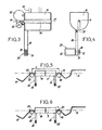
- the two bending heads 9 and 10 remaining in the normal working position on the axis 11 (see FIG. 2), moved alternately one towards the other along this axis 11, to execute bends alternately on the two halves of the tube to be bent 12. While a bending head 9 or 10 bends the desired angle in the corresponding tube half, this according to a bending plane determined by the orientation of its bending tools , the other bending head 10 or 9 maintains the tube 12 in the corresponding half. One of the bending heads 9 or 10 also maintains the tube 12 during bending while the other head is moved along the axis 11. This alternative bending process can continue, until the two heads 9 and 10 arrive in close proximity to each other, as shown in Figure 5, in the middle region of the tube 12.
- FIG. 5 shows that the last two elbows, which can be produced on the tube 12 by means of the respective bending tools of the two heads 9 and 10, are then separated at least by a distance E equal to substantially twice the length of a head of bending.
- the bending roller 23 of the first head 9 for example is first brought back to the starting position (corresponding to a zero bending angle), as shown Figure 6.
- the first bending head 9 is spaced from the initial axis 11 of the tube 12, over a distance D, so that the clamping means 27 carried by this head 9 is placed in the axis 11.
- the pinching means 27 are then actuated so as to firmly hold the tube 12, in its rectilinear part located between the last two elbows formed.
- the second bending head 10 is then moved along the axis 11 in the direction of the clamping means 27, without encountering any obstacle since the first head 9 has been previously overshadowed. This additional movement is illustrated in Figure 8.
Landscapes
- Engineering & Computer Science (AREA)
- Mechanical Engineering (AREA)
- Bending Of Plates, Rods, And Pipes (AREA)
Priority Applications (1)
| Application Number | Priority Date | Filing Date | Title |
|---|---|---|---|
| AT91420013T ATE93421T1 (de) | 1990-01-26 | 1991-01-17 | Rohrbiegevorrichtung mit zwei biegekoepfen. |
Applications Claiming Priority (2)
| Application Number | Priority Date | Filing Date | Title |
|---|---|---|---|
| FR9001574A FR2657546B1 (fr) | 1990-01-26 | 1990-01-26 | Machine a cintrer les tubes a deux tetes de cintrage. |
| FR9001574 | 1990-01-26 |
Publications (2)
| Publication Number | Publication Date |
|---|---|
| EP0445044A1 true EP0445044A1 (de) | 1991-09-04 |
| EP0445044B1 EP0445044B1 (de) | 1993-08-25 |
Family
ID=9393573
Family Applications (1)
| Application Number | Title | Priority Date | Filing Date |
|---|---|---|---|
| EP91420013A Expired - Lifetime EP0445044B1 (de) | 1990-01-26 | 1991-01-17 | Rohrbiegevorrichtung mit zwei Biegeköpfen |
Country Status (9)
| Country | Link |
|---|---|
| US (1) | US5113683A (de) |
| EP (1) | EP0445044B1 (de) |
| JP (1) | JPH05332A (de) |
| AT (1) | ATE93421T1 (de) |
| CA (1) | CA2034723A1 (de) |
| DE (1) | DE69100290T2 (de) |
| DK (1) | DK0445044T3 (de) |
| ES (1) | ES2043454T3 (de) |
| FR (1) | FR2657546B1 (de) |
Cited By (2)
| Publication number | Priority date | Publication date | Assignee | Title |
|---|---|---|---|---|
| EP0554533A1 (de) * | 1992-02-03 | 1993-08-11 | YASKAWA & COMPANY. Ltd. | Drahtbiegevorrichtung |
| CN102847851A (zh) * | 2012-09-29 | 2013-01-02 | 无锡威华电焊机制造有限公司 | 钢筋桁架腹杆筋同步送进打弯装置 |
Families Citing this family (18)
| Publication number | Priority date | Publication date | Assignee | Title |
|---|---|---|---|---|
| US5471857A (en) * | 1994-03-07 | 1995-12-05 | Mascotech Tubular Products, Inc. | Process for hydroforming a vehicle manifold |
| IT1292692B1 (it) * | 1997-03-20 | 1999-02-11 | Schnell Spa | Procedimento e macchina per la piegatura automatica di profilati e simili. |
| IT1290141B1 (it) * | 1997-03-21 | 1998-10-19 | Blm Spa | Macchina per curvare materiale filiforme come tubi barre o profilati |
| US6009737A (en) * | 1997-07-17 | 2000-01-04 | Arvin Industries, Inc. | Tube bender |
| US6155091A (en) * | 1999-02-26 | 2000-12-05 | Arvin Industries, Inc. | Mandrel assembly for tube-bending apparatus |
| FR2800649A1 (fr) * | 1999-11-04 | 2001-05-11 | Robolix Sa | Machine a cintrer ou a cambrer des profiles et unite de cintrage comprenant deux desdites machines a cintrer |
| US6230535B1 (en) * | 1999-11-18 | 2001-05-15 | Waitt/Fremont Machine L.L.C. | Wire bending apparatus |
| DE102004015073B3 (de) * | 2004-03-25 | 2005-10-06 | Langenstein & Schemann Gmbh | Vorrichtung und Verfahren zum Biegen eines Werkstücks |
| EP1955789B1 (de) * | 2007-02-07 | 2010-09-15 | WAFIOS Aktiengesellschaft | Biegemaschine |
| ATE429987T1 (de) * | 2007-03-14 | 2009-05-15 | Wafios Ag | Greifvorrichtung zum ergreifen und haltern länglicher werkstücke, insbesondere bei biegemaschinen |
| EP2008764B1 (de) * | 2007-06-29 | 2009-09-23 | WAFIOS Aktiengesellschaft | Linearführung |
| IT1401361B1 (it) * | 2010-06-10 | 2013-07-18 | Blm Spa | Macchina curvatubi con sistema di caricamento automatico e metodo per il caricamento automatico di tubi sulla testa di curvatura di una macchina curvatubi. |
| CN103632841B (zh) * | 2013-12-03 | 2015-09-30 | 慈溪市宏晟机械设备有限公司 | 一种电感线圈线端铆接成型机 |
| CN113600711B (zh) * | 2021-07-23 | 2023-04-11 | 上海建东科技有限公司 | 一种折弯机 |
| CN114603365B (zh) * | 2022-04-01 | 2023-05-23 | 杭州富阳海翔机械有限公司 | 一种搬运车的部件加工装置及其工艺方法 |
| CN115971298A (zh) * | 2022-12-14 | 2023-04-18 | 杭州格科机械有限公司 | 一种金属管道加工用折弯装置 |
| CN117600289B (zh) * | 2024-01-22 | 2024-04-19 | 中国建筑第五工程局有限公司 | 一种钢管弯折调直的成型设备 |
| US20250326613A1 (en) * | 2024-04-20 | 2025-10-23 | Joseph Homsy | Robotic Arms on a scissor lift with conduit bending apparatus and material for installation |
Citations (5)
| Publication number | Priority date | Publication date | Assignee | Title |
|---|---|---|---|---|
| DE2918813A1 (de) * | 1979-05-10 | 1980-11-20 | Brueninghaus Gmbh Stahlwerke | Vorrichtung zum biegen von metallstaeben |
| FR2602160A1 (fr) * | 1986-08-04 | 1988-02-05 | Latour Fils | Procede et machine modulaire de cambrage de fils metalliques |
| EP0263607A1 (de) * | 1986-09-27 | 1988-04-13 | Langbow Limited | Biegemaschinen |
| FR2610852A1 (fr) * | 1987-02-17 | 1988-08-19 | Picot Sa | Machine a cintrer les tubes, pourvue de deux tetes de cintrage |
| DE8908279U1 (de) * | 1989-05-11 | 1989-08-17 | Chuo Electric Mfg. Co., Ltd., Seto, Aichi | Biegeapparat zum Biegen langgestreckter Materialien in jeder Richtung |
Family Cites Families (6)
| Publication number | Priority date | Publication date | Assignee | Title |
|---|---|---|---|---|
| DE3312397A1 (de) * | 1983-04-06 | 1984-10-11 | Helmut 6230 Kriftel Zahlaus | Verfahren und vorrichtung zum biegen von stabfoermigen materialien |
| US4485658A (en) * | 1983-05-31 | 1984-12-04 | Stewart A K | Carriage assembly for a tube bending machine |
| US4662204A (en) * | 1985-01-17 | 1987-05-05 | Usui Kokusai Sangyo Kabushiki Kaisha | Apparatus for automatically bending metallic tubes |
| SE8503058L (sv) * | 1985-06-19 | 1986-12-20 | Asea Ab | Forfarande och installation for bockning av stangformigt material |
| DE3822713A1 (de) * | 1988-07-05 | 1990-01-18 | Heinz Ruhl | Vorrichtung zum bearbeiten von stangenmaterial |
| JPH0293920A (ja) * | 1988-09-30 | 1990-04-04 | Fuji Xerox Co Ltd | 入力装置 |
-
1990
- 1990-01-26 FR FR9001574A patent/FR2657546B1/fr not_active Expired - Lifetime
-
1991
- 1991-01-17 DK DK91420013.4T patent/DK0445044T3/da active
- 1991-01-17 AT AT91420013T patent/ATE93421T1/de not_active IP Right Cessation
- 1991-01-17 DE DE91420013T patent/DE69100290T2/de not_active Expired - Fee Related
- 1991-01-17 EP EP91420013A patent/EP0445044B1/de not_active Expired - Lifetime
- 1991-01-17 ES ES91420013T patent/ES2043454T3/es not_active Expired - Lifetime
- 1991-01-22 CA CA002034723A patent/CA2034723A1/fr not_active Abandoned
- 1991-01-24 JP JP3006982A patent/JPH05332A/ja active Pending
- 1991-01-25 US US07/645,974 patent/US5113683A/en not_active Expired - Fee Related
Patent Citations (5)
| Publication number | Priority date | Publication date | Assignee | Title |
|---|---|---|---|---|
| DE2918813A1 (de) * | 1979-05-10 | 1980-11-20 | Brueninghaus Gmbh Stahlwerke | Vorrichtung zum biegen von metallstaeben |
| FR2602160A1 (fr) * | 1986-08-04 | 1988-02-05 | Latour Fils | Procede et machine modulaire de cambrage de fils metalliques |
| EP0263607A1 (de) * | 1986-09-27 | 1988-04-13 | Langbow Limited | Biegemaschinen |
| FR2610852A1 (fr) * | 1987-02-17 | 1988-08-19 | Picot Sa | Machine a cintrer les tubes, pourvue de deux tetes de cintrage |
| DE8908279U1 (de) * | 1989-05-11 | 1989-08-17 | Chuo Electric Mfg. Co., Ltd., Seto, Aichi | Biegeapparat zum Biegen langgestreckter Materialien in jeder Richtung |
Cited By (3)
| Publication number | Priority date | Publication date | Assignee | Title |
|---|---|---|---|---|
| EP0554533A1 (de) * | 1992-02-03 | 1993-08-11 | YASKAWA & COMPANY. Ltd. | Drahtbiegevorrichtung |
| US5291771A (en) * | 1992-02-03 | 1994-03-08 | Yashawa & Company, Ltd. | Wire bending apparatus |
| CN102847851A (zh) * | 2012-09-29 | 2013-01-02 | 无锡威华电焊机制造有限公司 | 钢筋桁架腹杆筋同步送进打弯装置 |
Also Published As
| Publication number | Publication date |
|---|---|
| EP0445044B1 (de) | 1993-08-25 |
| DK0445044T3 (da) | 1993-11-22 |
| FR2657546A1 (fr) | 1991-08-02 |
| CA2034723A1 (fr) | 1991-07-27 |
| FR2657546B1 (fr) | 1992-05-22 |
| DE69100290D1 (de) | 1993-09-30 |
| DE69100290T2 (de) | 1993-12-23 |
| US5113683A (en) | 1992-05-19 |
| ATE93421T1 (de) | 1993-09-15 |
| ES2043454T3 (es) | 1993-12-16 |
| JPH05332A (ja) | 1993-01-08 |
Similar Documents
| Publication | Publication Date | Title |
|---|---|---|
| EP0445044B1 (de) | Rohrbiegevorrichtung mit zwei Biegeköpfen | |
| EP0069661B1 (de) | Automatische Blechbiegemaschine | |
| FR2596948A1 (fr) | Appareil a ebrancher les troncs d'arbres | |
| WO1985001898A1 (fr) | Machine automatique perfectionnee pour cambrer selon une configuration spatiale des elements minces et rectilignes, et notamment des fils metalliques | |
| EP1458505A1 (de) | Rohrbiegemaschine und links- und/oder rechtsbiegevorrichtung | |
| FR2609704A1 (fr) | Dispositif de montage de ressorts de tension automatique pour un siege de vehicule ou analogue | |
| EP1539392A1 (de) | Führungsstütze für eine rohrbiegemaschine | |
| WO2000016922A1 (fr) | Dispositif prehenseur pour le changement des outils de cintrage sur une machine a cintrer les tubes | |
| EP0281488B1 (de) | Drehender Biegekopf für Rohrbiegemaschine | |
| FR2833201A1 (fr) | Dispositif de transfert d'objets industriels entre deux positions | |
| FR2859653A1 (fr) | Machine orbitale pour le cintrage des tubes | |
| WO2001026867A1 (fr) | Machine automatique d'assemblage de cadres | |
| EP0000451B1 (de) | Klemme zum Festhalten von Gegenständen, Vorrichtung zum Anhängen zum Abhängen und zum Überlappen einer derartigen Klemme, und Anwendung dieser Klemme dieser Vorrichtung in Behandlungsanlagen | |
| EP0912265B1 (de) | Vorrichtung zum regeln der grösse eines werkzeugmaschinen-blechhalters | |
| FR2615050A1 (fr) | Dispositif de pose et de sertissage d'embouts sur des conducteurs electriques | |
| FR2737674A1 (fr) | Machine a cintrer les tubes avec dispositif de poussee | |
| EP0320408B1 (de) | Steuerungsvorrichtung für die Reglette einer Rohrbiegemaschine | |
| EP0220967A1 (de) | Transportvorrichtung für Behälter | |
| EP0617683B1 (de) | Vorrichtung zum trennen von zwei folien aus biegsamem material | |
| WO1997017626A1 (fr) | Procede pour denuder une fibre optique ou un ruban de fibres optiques et appareil pour sa mise en oeuvre | |
| FR2800651A1 (fr) | Machine a former des extremites de tubes, et dispositif de formage comportant deux desdites machines a former | |
| FR2529486A1 (fr) | Procede et dispositif pour le pliage de tubes a paroi mince, notamment de ressorts de manometre | |
| FR2681584A1 (fr) | Dispositif pour la separation de feuilles en matiere souple. | |
| FR2746682A1 (fr) | Machine a cambrer les fils metalliques | |
| EP0236213A1 (de) | Automatisches Verfahren zur Herstellung von Spulen ohne Stützgestell und zum Anbringen derselben auf eine Leiterplatte und Maschine zur Ausführung |
Legal Events
| Date | Code | Title | Description |
|---|---|---|---|
| PUAI | Public reference made under article 153(3) epc to a published international application that has entered the european phase |
Free format text: ORIGINAL CODE: 0009012 |
|
| AK | Designated contracting states |
Kind code of ref document: A1 Designated state(s): AT BE DE DK ES GB IT LU NL SE |
|
| 17P | Request for examination filed |
Effective date: 19920118 |
|
| 17Q | First examination report despatched |
Effective date: 19921020 |
|
| GRAA | (expected) grant |
Free format text: ORIGINAL CODE: 0009210 |
|
| AK | Designated contracting states |
Kind code of ref document: B1 Designated state(s): AT BE DE DK ES GB IT LU NL SE |
|
| REF | Corresponds to: |
Ref document number: 93421 Country of ref document: AT Date of ref document: 19930915 Kind code of ref document: T |
|
| ITF | It: translation for a ep patent filed | ||
| REF | Corresponds to: |
Ref document number: 69100290 Country of ref document: DE Date of ref document: 19930930 |
|
| GBT | Gb: translation of ep patent filed (gb section 77(6)(a)/1977) |
Effective date: 19931014 |
|
| REG | Reference to a national code |
Ref country code: DK Ref legal event code: T3 |
|
| REG | Reference to a national code |
Ref country code: ES Ref legal event code: FG2A Ref document number: 2043454 Country of ref document: ES Kind code of ref document: T3 |
|
| EPTA | Lu: last paid annual fee | ||
| PLBE | No opposition filed within time limit |
Free format text: ORIGINAL CODE: 0009261 |
|
| STAA | Information on the status of an ep patent application or granted ep patent |
Free format text: STATUS: NO OPPOSITION FILED WITHIN TIME LIMIT |
|
| 26N | No opposition filed | ||
| PGFP | Annual fee paid to national office [announced via postgrant information from national office to epo] |
Ref country code: LU Payment date: 19950101 Year of fee payment: 5 |
|
| PGFP | Annual fee paid to national office [announced via postgrant information from national office to epo] |
Ref country code: GB Payment date: 19950125 Year of fee payment: 5 Ref country code: BE Payment date: 19950125 Year of fee payment: 5 |
|
| PGFP | Annual fee paid to national office [announced via postgrant information from national office to epo] |
Ref country code: DK Payment date: 19950126 Year of fee payment: 5 |
|
| PGFP | Annual fee paid to national office [announced via postgrant information from national office to epo] |
Ref country code: SE Payment date: 19950127 Year of fee payment: 5 Ref country code: DE Payment date: 19950127 Year of fee payment: 5 |
|
| PGFP | Annual fee paid to national office [announced via postgrant information from national office to epo] |
Ref country code: ES Payment date: 19950130 Year of fee payment: 5 Ref country code: AT Payment date: 19950130 Year of fee payment: 5 |
|
| EAL | Se: european patent in force in sweden |
Ref document number: 91420013.4 |
|
| PGFP | Annual fee paid to national office [announced via postgrant information from national office to epo] |
Ref country code: NL Payment date: 19950131 Year of fee payment: 5 |
|
| PG25 | Lapsed in a contracting state [announced via postgrant information from national office to epo] |
Ref country code: LU Free format text: LAPSE BECAUSE OF NON-PAYMENT OF DUE FEES Effective date: 19960117 Ref country code: GB Effective date: 19960117 Ref country code: DK Effective date: 19960117 Ref country code: AT Effective date: 19960117 |
|
| REG | Reference to a national code |
Ref country code: DK Ref legal event code: EBP |
|
| PG25 | Lapsed in a contracting state [announced via postgrant information from national office to epo] |
Ref country code: SE Effective date: 19960118 Ref country code: ES Free format text: LAPSE BECAUSE OF NON-PAYMENT OF DUE FEES Effective date: 19960118 |
|
| PG25 | Lapsed in a contracting state [announced via postgrant information from national office to epo] |
Ref country code: BE Effective date: 19960131 |
|
| BERE | Be: lapsed |
Owner name: S.A. EATON LEONARD PICOT Effective date: 19960131 |
|
| PG25 | Lapsed in a contracting state [announced via postgrant information from national office to epo] |
Ref country code: NL Effective date: 19960801 |
|
| GBPC | Gb: european patent ceased through non-payment of renewal fee |
Effective date: 19960117 |
|
| NLV4 | Nl: lapsed or anulled due to non-payment of the annual fee |
Effective date: 19960801 |
|
| PG25 | Lapsed in a contracting state [announced via postgrant information from national office to epo] |
Ref country code: DE Effective date: 19961001 |
|
| EUG | Se: european patent has lapsed |
Ref document number: 91420013.4 |
|
| REG | Reference to a national code |
Ref country code: ES Ref legal event code: FD2A Effective date: 19990503 |
|
| PG25 | Lapsed in a contracting state [announced via postgrant information from national office to epo] |
Ref country code: IT Free format text: LAPSE BECAUSE OF NON-PAYMENT OF DUE FEES;WARNING: LAPSES OF ITALIAN PATENTS WITH EFFECTIVE DATE BEFORE 2007 MAY HAVE OCCURRED AT ANY TIME BEFORE 2007. THE CORRECT EFFECTIVE DATE MAY BE DIFFERENT FROM THE ONE RECORDED. Effective date: 20050117 |