EP0445052A1 - Automatische Plastiktütenabgabevorrichtung, insbesondere von Polyäthylen - Google Patents
Automatische Plastiktütenabgabevorrichtung, insbesondere von Polyäthylen Download PDFInfo
- Publication number
- EP0445052A1 EP0445052A1 EP91420069A EP91420069A EP0445052A1 EP 0445052 A1 EP0445052 A1 EP 0445052A1 EP 91420069 A EP91420069 A EP 91420069A EP 91420069 A EP91420069 A EP 91420069A EP 0445052 A1 EP0445052 A1 EP 0445052A1
- Authority
- EP
- European Patent Office
- Prior art keywords
- bags
- machine according
- frame
- bag
- cover
- Prior art date
- Legal status (The legal status is an assumption and is not a legal conclusion. Google has not performed a legal analysis and makes no representation as to the accuracy of the status listed.)
- Withdrawn
Links
- 229920003023 plastic Polymers 0.000 title claims abstract description 27
- 239000004033 plastic Substances 0.000 title claims abstract description 27
- 239000004698 Polyethylene Substances 0.000 title description 3
- -1 polyethylene Polymers 0.000 title description 3
- 229920000573 polyethylene Polymers 0.000 title description 3
- 125000006850 spacer group Chemical group 0.000 claims description 7
- 230000001276 controlling effect Effects 0.000 claims description 5
- 230000001105 regulatory effect Effects 0.000 claims description 4
- 238000012360 testing method Methods 0.000 claims description 4
- 230000000694 effects Effects 0.000 claims description 3
- 238000009434 installation Methods 0.000 claims description 3
- 230000005540 biological transmission Effects 0.000 claims description 2
- 238000006073 displacement reaction Methods 0.000 claims description 2
- 238000003825 pressing Methods 0.000 abstract 1
- 238000000034 method Methods 0.000 description 7
- 239000000463 material Substances 0.000 description 5
- 238000004806 packaging method and process Methods 0.000 description 5
- 230000008901 benefit Effects 0.000 description 4
- 210000003811 finger Anatomy 0.000 description 4
- 230000007246 mechanism Effects 0.000 description 4
- 238000013461 design Methods 0.000 description 2
- 238000000605 extraction Methods 0.000 description 2
- 230000010354 integration Effects 0.000 description 2
- 238000012423 maintenance Methods 0.000 description 2
- 238000005096 rolling process Methods 0.000 description 2
- 238000000926 separation method Methods 0.000 description 2
- 238000012546 transfer Methods 0.000 description 2
- 239000002699 waste material Substances 0.000 description 2
- KRQUFUKTQHISJB-YYADALCUSA-N 2-[(E)-N-[2-(4-chlorophenoxy)propoxy]-C-propylcarbonimidoyl]-3-hydroxy-5-(thian-3-yl)cyclohex-2-en-1-one Chemical compound CCC\C(=N/OCC(C)OC1=CC=C(Cl)C=C1)C1=C(O)CC(CC1=O)C1CCCSC1 KRQUFUKTQHISJB-YYADALCUSA-N 0.000 description 1
- 230000006978 adaptation Effects 0.000 description 1
- 230000000712 assembly Effects 0.000 description 1
- 238000000429 assembly Methods 0.000 description 1
- 238000010276 construction Methods 0.000 description 1
- 230000007547 defect Effects 0.000 description 1
- 230000005489 elastic deformation Effects 0.000 description 1
- 230000002708 enhancing effect Effects 0.000 description 1
- 238000003780 insertion Methods 0.000 description 1
- 230000037431 insertion Effects 0.000 description 1
- 230000003287 optical effect Effects 0.000 description 1
- 230000001681 protective effect Effects 0.000 description 1
- 230000002441 reversible effect Effects 0.000 description 1
- 210000003813 thumb Anatomy 0.000 description 1
- 230000001960 triggered effect Effects 0.000 description 1
- 230000002747 voluntary effect Effects 0.000 description 1
Images



Classifications
-
- B—PERFORMING OPERATIONS; TRANSPORTING
- B65—CONVEYING; PACKING; STORING; HANDLING THIN OR FILAMENTARY MATERIAL
- B65B—MACHINES, APPARATUS OR DEVICES FOR, OR METHODS OF, PACKAGING ARTICLES OR MATERIALS; UNPACKING
- B65B43/00—Forming, feeding, opening or setting-up containers or receptacles in association with packaging
- B65B43/12—Feeding flexible bags or carton blanks in flat or collapsed state; Feeding flat bags connected to form a series or chain
- B65B43/14—Feeding individual bags or carton blanks from piles or magazines
-
- A—HUMAN NECESSITIES
- A47—FURNITURE; DOMESTIC ARTICLES OR APPLIANCES; COFFEE MILLS; SPICE MILLS; SUCTION CLEANERS IN GENERAL
- A47F—SPECIAL FURNITURE, FITTINGS, OR ACCESSORIES FOR SHOPS, STOREHOUSES, BARS, RESTAURANTS OR THE LIKE; PAYING COUNTERS
- A47F9/00—Shop, bar, bank or like counters
- A47F9/02—Paying counters
- A47F9/04—Check-out counters, e.g. for self-service stores
- A47F9/042—Shopping bags or carton-dispensing systems therefor
Definitions
- the invention relates to the technical sector of machines and equipment for the automatic distribution of plastic bags which can find uses for example at the various cash desks of stores.
- the plastic bags constitute a preferred packaging in stores by its well-known characteristics of low cost, ease of storage, ease of printing with the brand of the seller or the distributor. These bags which are for example made in bundles are particularly practical for stores where the consumer freely chooses his products, stores them pell-mell in shopping carts, then goes to the checkout; the cashiers then give the customer one or more bags depending on the size of the purchases to store them in said bags. There are thus several techniques for distributing bags, either the cashier gives a lot of bags, and there is often waste by giving too many bags, or there are bag dispensing machines. In the latter case, the materials must be reliable, with a large capacity for storing bags to avoid too frequent supply.
- the existing equipment is bulky and is arranged next to cash desks, constituting an annoyance despite everything both for the cashiers and for the customer base.
- Patent DE No. 2,118,831 also discloses an installation arranged and associated with a cash register allowing the removal of paper bags at the request of a customer.
- the bags are placed on a loader then by complex means actuated by an order triggered by the customer, the bags are distributed one by one through an opening formed laterally on the casing of the machine.
- the mechanisms are complex, the loading not very easy and the transfer of the bag not very easy for its selective distribution.
- a first object according to the invention was to design a machine with a great autonomy of operation which allows a controlled automatic distribution of plastic bags one by one, in particular in polyethylene.
- Another object according to the invention was to provide a machine which allows the distribution of bags regardless of the plastic material chosen, avoiding gripping of several bags at the same time.
- Another object according to the invention was to allow its integration into a cash register.
- Another object according to the invention was to allow the cashier of a cash desk to act, control and limit the number of bags taken by the customer.
- the machine for the automatic distribution of plastic bags is remarkable in that it comprises a frame of parallelepipedal shape allowing the introduction, engagement and positioning of a device for loading stacked plastic bags and the various means of ordered ; and in that the frame has in its upper part an articulated cover arranged to receive a device for pressurizing the bags, means allowing the unit to be removed from the bags, means allowing the remote control of the operation of the loader , and means for regulating the positioning of the loading device, in particular ensuring that it is locked in position in order to block the distribution of the bags.
- the frame receives on its upper face an articulated cover arranged with a frame consisting of profiled elements and allowing the positioning of a protection plane and a plate arranged with a profiled opening allowing the introduction of the fingers of the user for gripping the bags one by one, said cover being arranged to receive and ensure the articulation of a device for pressurizing the bags.
- the pressurizing device is fixed to a spacer placed on the frame of the cover and comprises an articulated arm associated with a balance articulated with respect to an axis, limiters of stroke defining the limit positions of the device.
- a control means is capable of being actuated by a party by acting on the pressurizing device and on the position of the bag loader to block or generate the removal of the bags.
- the machine includes a device for creasing the bags.
- the machine comprises one or more ramps or mats receiving brushes to allow support and contact on the stacks of bags, ramps being arranged vertically in the frame in adjustable lateral contact against said bags, and ramps arranged horizontally from above on the apparent bag.
- the cover is arranged internally to receive a plate with controlled transverse movement, said plate having on all or part of its surface brushes capable of coming to bear on the opposite face of the upper bag disposed on the loader.
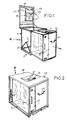
- the automatic bag dispensing machine is referenced as a whole by (M). It is designed and arranged to be entirely removable, being able to constitute an independent unit or to be integrated with other assemblies such as, for example, cash desks for certain types of stores.
- the machine constitutes an independent unit.
- the machine is integrated into the cash register.
- the machine can advantageously be constituted in the form of an independent module integrated or not in the cash register and which can be transferred, as required, from one cash bench to another.
- the machine whatever its construction, is arranged with a frame internally receiving a device for loading and presenting stacked plastic bags and various control means, the frame having in its upper part an articulated cover. to receive a device for pressurizing the bags, means allowing the remote control of the operation of the loading device and presentation of the bags, said cover being arranged with a profiled opening allowing the introduction of fingers of use for the controlled gripping of bags.
- This machine comprises a frame (1) of parallelepiped shape, this frame being in a fixed position or mounted on rolling means to allow its movement.
- This frame allows the introduction, engagement, and positioning of a carriage (2) arranged to receive the loader (3) of plastic bags (4) stacked and the various control means.
- This trolley is thus movable to allow loading into bags and possible maintenance of the device.
- a device is provided for connecting the trolley to the rear lower base of the frame.
- connection device comprises an articulated arm (5) forming a compass, one end (5.1) of which is fixed to the lower base of the frame and the other (5.2) to the rear face of the carriage or the bottom face of it.
- the amplitude of articulation and opening of the arm (5) is such that it allows the carriage to be released from the frame.
- the trolley is arranged internally to receive the device for loading plastic bags. As it appears in the drawings, the carriage is arranged with a compartment internally receiving the means for controlling the movement in height of a tray (6) for receiving plastic bags.
- the charger device is directly integrated in the frame arranged near or in the cash desk without being movable.
- the control means of the charger device thus comprise a motor unit (7) fixed on an associated support (7,1) to one of the walls of the carriage.
- This motor drives by means of transmission and return (8), a screw (9) disposed vertically in the carriage and slidingly receiving a ring (10) from which the above-mentioned plate (6) is disposed horizontally.
- Links of the aforementioned type are part of the current technique.
- This tray comprises from a fixed base support advantageously two panels forming drawers (6,1-6,2) adjustable in spacing relative to each other and allowing an adaptation of their length according to the length plastic bags. These panels thus partially overlap one on the other in the transverse middle part of the carriage. They are assembled and separated from each other by any appropriate connection means. Their spacing is a function of the dimensional characteristics of the bags to be received, and the spacing is adjusted and the position is maintained by conventional connecting means.
- the carriage is accessible laterally by two doors (11) while a handle (12) allows insertion into the frame or extraction.
- the bags are stacked on a tray (6) fixed in any suitable manner to a support structure (43) with deformable parallelogram or the like, controlled by any suitable means.
- the worm can be coupled by dial (44) and flexible (45) to a motor block (46) with electrobrake.
- the plastic bags are unloaded from their packaging packaging on the tray after separation of the lower flaps of said packaging.
- the bags are put in place after the cover (13) of the frame has been raised.
- the frame receives on its upper face a cover (13) articulated on the rear upper base of the chassis.
- This cover is arranged with a frame (14) established from profiled elements, metallic for example, to allow the positioning of a protective surface (15) profiled and giving an exterior aesthetic to the machine.
- the cover is arranged to receive a device for pressurizing the bags which will be described later, as well as a plate (16) provided with a profiled opening (17) to allow the introduction of the fingers of a buyer. or customer who wishes to collect the bags.
- the cover has a profiled recess (13,1) oriented on the inside of the machine of a certain depth and against the internal face of which the aforementioned plate (16) is fixed. The depth of this recess is a function of the maximum loading height of the plastic bag receiving tray, and this to allow practical and easy gripping of the bags one by one.
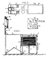
- the cutout or opening (17) is for example established in the form of a cross, according to FIG. 16, to allow only the introduction of the thumb and the index finger of the client for gripping a bag.
- This form can however be different according to the needs.
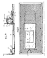
- This cut can alternatively have the shape (47) illustrated in Figure 11. It is located eccentric to the median plane of the support plate. It is profiled with a central zone (47.1) widened and flared by extending (47.2) on either side and in the longitudinal plane corresponding to the location of the bags over a large part of the length of the plate. The ends are curved appreciably. Such a profile is advantageous and allows good extraction of the plastic bags one by one. and their guidance during the evacuation.
- the device is intended to control the elevation of the loader assembly as a function of the needs in stock of bags.
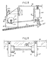
- the device is fixed to a spacer (18) arranged transversely on the frame of the cover (13).
- the device thus comprises an arm (19) U-shaped, the end parts (19,2) of the branches (19,1) are fixed to articulation means while the bottom part of the arm comes to bear on the upper bag stored on the charger.
- the arms of the arm are arranged with rolling means of the ball type (20) which are introduced by sliding on the arms (19,1) and thus allowing good evacuation of the sampled bags.
- the articulation of the arm is for example that illustrated in the drawings.
- the arm is positioned relative to a balance (21) comprising an L-shaped plate (22), the lower branch of which is coupled in an adjustable manner by a connecting screw (23) to an axis (24) disposed transversely on the frame. of the cover.
- Flanges (25) are arranged and fixed laterally on the frame and are arranged with an opening for the passage of the ends of the axis.
- Bearings (26) allowing the rotation of the axis are attached and fixed on the flanges.
- the L-shaped plate is coupled at its rear end with a L-shaped return piece (27) itself ensuring a connection with the branches of the aforementioned arm.
- the return plate is secured by screwing to the plate (22), while a return spring (28) is fixed to the spacer (18) and to the return plate so as to define a constant elastic deformation capacity. .
- the balance defined by the arm, the deflection piece and the profiled plate (22) pivots relative to the axis (24) within the limits which are defined by two limit switches (30-31).
- a first limit switch (30) is fixed to the connecting spacer (18) and is substantially in the horizontal position. Its stop part comes opposite the vertical free end of the profiled plate (22). This limit switch regulates the balance level.
- the second limit switch (31) is disposed on the deflection face (27) while its end projects into an upper plane to come into contact, if necessary, with an adjustable stop (32) fixed in a vertical plane from the 'spacer (18) connecting. It allows when the machine stops the maximum tilting of the pendulum to cause its maximum support on the bags arranged on the loader and avoid their lifting.
- the pressurizing mechanism is closely combined with the charger so that there is close coordination of operation.
- the balance is raised and the vertical part of the plate (22) is in contact with the limit switch (31).
- the pendulum swings down, which tends to raise its rear part and bring the second limit switch (31) into contact with the adjustable stop.
- the engine is reset and the bag loader continues to rise.
- a control circuit capable of being actuated directly by an operator and the cashier in particular.
- the circuit includes means making it possible to act on the loader motor, and to lower the latter in order to prevent the customer from grabbing the bags. This intervention can be carried out when the machine is put to rest and not used, or else as part of a voluntary and punctual intervention, if there is an excess of bag removal by the customer.
- pressurizing device is located towards the front of the machine and behind the hollowed-out central area of the cover. The device is therefore well protected.
- the spacer (18) is arranged in L and receives on its vertical branch a limit switch (30).
- the lateral flanges (25) between which the axis (24) is arranged allow the positioning of the pendulum (22).
- the vertical branch of the latter receives an end stop (48) opposite the end stop (30) to control and regulate the tilting amplitude of the balance, the horizontal lower part of the balance is secured by screwing or other to a plate (49) for holding the underlying bags.
- the limit switch (27) is fixed to the inner side of the plate (18) and comes into contact with the abutment (50) associated with the lower wing of the balance.
- the balance is associated with the abacus arm (19) whose U-shape is arranged to receive a plurality of balls over its entire profile.
- the connection of the abacus to the pendulum takes place via a transverse connection plate (51).
- the end of the abacus which bears on the bags, has, at the end, a test pattern (52) or equivalent means capable of constituting a means of adjusting and regulating the height of the position of the abacus-pendulum assembly depending on the change of bags.
- a proximity detector (53) is then provided fixed on the frame of the installation in order to cooperate with said test pattern, the detector being associated with control means for controlling the positioning and pendulum articulation.
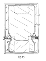
- one or more ramps of brushes or mats are used which can facilitate the separation of the bags from one another. Illustrated for example two ramps (54 - 55) of brushes arranged vertically on the lateral sides of the bags, as well as two ramps of brushes (56 - 57) which can act transversely on the edges of the bags. In the latter case, a first ramp (56) of brushes is arranged and fixed on the pendulum projecting downward, while a second ramp (57) of brushes is arranged fixed on the support member of the staff.
- the vertically arranged brush ramps (54 - 55) are adjustable in position to penetrate substantially and in a controlled manner into the thickness of the stack of stored bags.
- This plate is presented in a grid form with brushes visible downwards to come into contact over all or part of the surface opposite the upper bag presented.
- the cover (13) is arranged in its lower part with a shutter member (58) capable of being translated to close the profiled opening for taking bags. More particularly, said member is a flap of shape and profile corresponding to the bottom of the cover, said flap being guided by profiled slides (59) formed in the cover body.
- the shutter is associated with a means (60) ensuring its movement.
- this means (60) is constituted by a rack (61) meshing with a pinion (62) mounted at the end of a shaft (63) of a micromotor with reversible control. The latter can thus be requested by the operator and be ordered to open-close according to the conditions of use or non-use of the machine.
- This shutter constitutes additional security. It can be made of a transparent or other plastic material.
- the machine can comprise a device for crumpling bags. It has in fact been found that, depending on the nature of the material constituting the plastic bags, there could be a withdrawal of several bags simultaneously by their adhesion effect between them.
- the machine is thus arranged with a crumpling device which is positioned near the opening for taking bags from the customers.
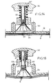
- the device thus comprises a profiled outer body (33) which is fixed by any means of connection to the cover.
- An opening (34) is provided on the cover and / or the plate (16) to allow the passage and bringing the crumpling device into contact with the bag.
- the device comprises an operating shaft (35) passing through the body (33) and having at its upper part a knob (36) for operating and gripping.
- a return spring (37) is introduced on the axis and abuts against a flange (35,1) formed at the upper end of the axis and on the upper face of the aforementioned body.
- the axis (35) extends at its lower end into the body to receive a profiled means (43) intended to come into contact with the upper bag.
- This means (43) can advantageously be a suction cup.
- the customer must perform an operation on the knob lowering the axis and allowing the suction cup to come into contact with the bag, then by carrying out a slight rotational movement of the axis on itself, it causes the upper bag to crumple by the action of the suction cup. The customer can then easily grasp the bag through the profiled opening formed on the cover.
- the crumpling operation can be carried out by a single support operation requested from the client by adapting the crumpling mechanism.
- the bearing movement on the axis by the customer simultaneously causes its rotation by any known mechanical means.
- the machine according to the invention is particularly suitable for the controlled automatic distribution of bags. It can be included as is near a cash register in certain types of stores. It can alternatively allow a new layout of the bench by integrating therein as it appears in FIG. 3 of the drawings.
- the cash desk (38) can have, beyond the reception areas (39) for goods and the optical reader (40) of the product bar codes, two reception bins (41) for goods extending by separate trays (42) for filling the bags and between which the machine according to the invention is arranged integrated into the bench. It is then conceivable that the machine is integrated as is in its housing provided for this purpose in the bench, or alternatively only introduce the carriage part, the frame and cover then being obviously arranged from the structure of the cash register cited above.
Landscapes
- Engineering & Computer Science (AREA)
- Mechanical Engineering (AREA)
- Auxiliary Devices For And Details Of Packaging Control (AREA)
Applications Claiming Priority (2)
| Application Number | Priority Date | Filing Date | Title |
|---|---|---|---|
| FR9002893 | 1990-03-01 | ||
| FR9002893A FR2659070B1 (fr) | 1990-03-01 | 1990-03-01 | Machine pour la distribution automatique de sacs plastiques. |
Publications (1)
| Publication Number | Publication Date |
|---|---|
| EP0445052A1 true EP0445052A1 (de) | 1991-09-04 |
Family
ID=9394479
Family Applications (1)
| Application Number | Title | Priority Date | Filing Date |
|---|---|---|---|
| EP91420069A Withdrawn EP0445052A1 (de) | 1990-03-01 | 1991-02-28 | Automatische Plastiktütenabgabevorrichtung, insbesondere von Polyäthylen |
Country Status (2)
| Country | Link |
|---|---|
| EP (1) | EP0445052A1 (de) |
| FR (1) | FR2659070B1 (de) |
Cited By (2)
| Publication number | Priority date | Publication date | Assignee | Title |
|---|---|---|---|---|
| WO2006101819A1 (en) * | 2005-03-18 | 2006-09-28 | Cargill, Incorporated | Bag stabilizer |
| CN115818299A (zh) * | 2022-12-19 | 2023-03-21 | 南通林泰克斯新材料科技有限公司 | 一种适用薄件料的自动上料装置 |
Citations (5)
| Publication number | Priority date | Publication date | Assignee | Title |
|---|---|---|---|---|
| US2909020A (en) * | 1958-06-23 | 1959-10-20 | Almor Company | Checkout bagging counter |
| FR1577459A (de) * | 1968-05-27 | 1969-08-08 | ||
| DE2118831A1 (de) * | 1971-04-17 | 1972-11-09 | Wilfried Pavel KG Maschinen- und Apparatebau, 4801 Hessein | Gerät zur vereinzelten Ausgabe von Tragetaschen oder Tüten |
| DE2256958A1 (de) * | 1971-12-06 | 1973-06-14 | Akerlund & Rausing Ab | Ladenausruestung |
| DE2506672A1 (de) * | 1975-02-17 | 1976-08-26 | Ernst Eberle | Ausgabegeraet fuer folientaschen |
-
1990
- 1990-03-01 FR FR9002893A patent/FR2659070B1/fr not_active Expired - Lifetime
-
1991
- 1991-02-28 EP EP91420069A patent/EP0445052A1/de not_active Withdrawn
Patent Citations (5)
| Publication number | Priority date | Publication date | Assignee | Title |
|---|---|---|---|---|
| US2909020A (en) * | 1958-06-23 | 1959-10-20 | Almor Company | Checkout bagging counter |
| FR1577459A (de) * | 1968-05-27 | 1969-08-08 | ||
| DE2118831A1 (de) * | 1971-04-17 | 1972-11-09 | Wilfried Pavel KG Maschinen- und Apparatebau, 4801 Hessein | Gerät zur vereinzelten Ausgabe von Tragetaschen oder Tüten |
| DE2256958A1 (de) * | 1971-12-06 | 1973-06-14 | Akerlund & Rausing Ab | Ladenausruestung |
| DE2506672A1 (de) * | 1975-02-17 | 1976-08-26 | Ernst Eberle | Ausgabegeraet fuer folientaschen |
Cited By (2)
| Publication number | Priority date | Publication date | Assignee | Title |
|---|---|---|---|---|
| WO2006101819A1 (en) * | 2005-03-18 | 2006-09-28 | Cargill, Incorporated | Bag stabilizer |
| CN115818299A (zh) * | 2022-12-19 | 2023-03-21 | 南通林泰克斯新材料科技有限公司 | 一种适用薄件料的自动上料装置 |
Also Published As
| Publication number | Publication date |
|---|---|
| FR2659070B1 (fr) | 1992-07-10 |
| FR2659070A1 (fr) | 1991-09-06 |
Similar Documents
| Publication | Publication Date | Title |
|---|---|---|
| EP0275490B1 (de) | Ausgeber für flache Gegenstände | |
| EP0905660B1 (de) | Vorrichtung zum Lösen und Spenden von Artikeln | |
| FR2589840A1 (fr) | Conteneur et procede pour charger des billets de banque dans une cassette a billets | |
| CA1307546C (fr) | Appareil pour distribuer automatiquement des objets laminaires | |
| EP0632917B1 (de) | Automatische ausgeber für zeitungen u.d. mit auswahlmöglichkeiten | |
| CA2231344A1 (fr) | Dispositif de distributeur automatique de sachets | |
| FR2568703A1 (fr) | Appareil distributeur distribuant des gobelets contenant des boissons fabriquees instantanement | |
| FR2600991A1 (fr) | Distributeur d'elements minces empiles, muni d'un dispositif d'extraction de ces derniers, et boite-cartouche d'elements minces susceptible d'equiper un tel distributeur | |
| EP0233232B1 (de) | Vorrichtung zur verteilung und zum verkauf von biegsamen trägern | |
| WO2011020956A1 (fr) | Systeme de stockage et de delivrance de boites parallelepipediques telles que des boites de medicament | |
| EP0445052A1 (de) | Automatische Plastiktütenabgabevorrichtung, insbesondere von Polyäthylen | |
| FR2664802A1 (fr) | Appareil de distribution automatique de produits en bidons ou autres. | |
| BE1009279A3 (fr) | Dispositif de reception et de tri d'objets divers, notamment de recipients a mettre au rebut. | |
| WO1991001536A1 (fr) | Magasin a distribution automatique | |
| FR3075440A1 (fr) | Borne de distribution d'echantillons de produits cosmetiques et/ou de parfum | |
| EP4188867A1 (de) | Vorrichtung zur abgabe eines produkts, insbesondere eines in einen flexiblen beutel gefüllten fluids | |
| FR3098212A1 (fr) | Appareil de distribution d’un produit contenu dans une poche de stockage | |
| WO1992015076A1 (fr) | Distributeur automatique d'articles conditionnes | |
| FR3084569A1 (fr) | Systeme de distribution de denrees alimentaires en vrac, et notamment de fruits secs en vrac | |
| FR3131285A1 (fr) | Installation de distribution de boissons dans des recipients notamment de type canette | |
| EP0633209A1 (de) | Vorrichtung und Verfahren zum Ausgeben von flachen Produkten | |
| EP0074906B1 (de) | Autographisches Register | |
| WO2024141472A1 (fr) | Machine de distribution de vrac | |
| FR2952916A1 (fr) | Module de stockage de gobelets, par exemple usages, et dispositif de collecte de gobelets usages comportant un tel module. | |
| FR2846315A1 (fr) | Dispositif pour prelever des objets empiles les uns sur les autres |
Legal Events
| Date | Code | Title | Description |
|---|---|---|---|
| PUAI | Public reference made under article 153(3) epc to a published international application that has entered the european phase |
Free format text: ORIGINAL CODE: 0009012 |
|
| AK | Designated contracting states |
Kind code of ref document: A1 Designated state(s): BE CH DE ES FR GB IT LI |
|
| 17P | Request for examination filed |
Effective date: 19920226 |
|
| STAA | Information on the status of an ep patent application or granted ep patent |
Free format text: STATUS: THE APPLICATION IS DEEMED TO BE WITHDRAWN |
|
| 18D | Application deemed to be withdrawn |
Effective date: 19930901 |