EP0905660B1 - Vorrichtung zum Lösen und Spenden von Artikeln - Google Patents
Vorrichtung zum Lösen und Spenden von Artikeln Download PDFInfo
- Publication number
- EP0905660B1 EP0905660B1 EP98870197A EP98870197A EP0905660B1 EP 0905660 B1 EP0905660 B1 EP 0905660B1 EP 98870197 A EP98870197 A EP 98870197A EP 98870197 A EP98870197 A EP 98870197A EP 0905660 B1 EP0905660 B1 EP 0905660B1
- Authority
- EP
- European Patent Office
- Prior art keywords
- carriage
- finger
- ducts
- movement
- control element
- Prior art date
- Legal status (The legal status is an assumption and is not a legal conclusion. Google has not performed a legal analysis and makes no representation as to the accuracy of the status listed.)
- Expired - Lifetime
Links
- 230000002441 reversible effect Effects 0.000 claims description 2
- 210000002445 nipple Anatomy 0.000 description 5
- 230000007246 mechanism Effects 0.000 description 4
- 240000000528 Ricinus communis Species 0.000 description 2
- 235000004443 Ricinus communis Nutrition 0.000 description 2
- 230000009471 action Effects 0.000 description 2
- 238000013459 approach Methods 0.000 description 2
- 239000002184 metal Substances 0.000 description 2
- 208000035874 Excoriation Diseases 0.000 description 1
- 240000008042 Zea mays Species 0.000 description 1
- 238000005299 abrasion Methods 0.000 description 1
- 230000000903 blocking effect Effects 0.000 description 1
- 239000000969 carrier Substances 0.000 description 1
- 239000004020 conductor Substances 0.000 description 1
- 238000006073 displacement reaction Methods 0.000 description 1
- 230000000694 effects Effects 0.000 description 1
- 238000003780 insertion Methods 0.000 description 1
- 230000037431 insertion Effects 0.000 description 1
- 238000009434 installation Methods 0.000 description 1
- 230000003287 optical effect Effects 0.000 description 1
- 238000004806 packaging method and process Methods 0.000 description 1
- 230000007420 reactivation Effects 0.000 description 1
- 230000000284 resting effect Effects 0.000 description 1
- 239000010409 thin film Substances 0.000 description 1
Images


Classifications
-
- G—PHYSICS
- G07—CHECKING-DEVICES
- G07F—COIN-FREED OR LIKE APPARATUS
- G07F11/00—Coin-freed apparatus for dispensing, or the like, discrete articles
- G07F11/02—Coin-freed apparatus for dispensing, or the like, discrete articles from non-movable magazines
- G07F11/04—Coin-freed apparatus for dispensing, or the like, discrete articles from non-movable magazines in which magazines the articles are stored one vertically above the other
- G07F11/16—Delivery means
- G07F11/26—Endless bands
-
- G—PHYSICS
- G07—CHECKING-DEVICES
- G07F—COIN-FREED OR LIKE APPARATUS
- G07F11/00—Coin-freed apparatus for dispensing, or the like, discrete articles
- G07F11/02—Coin-freed apparatus for dispensing, or the like, discrete articles from non-movable magazines
- G07F11/04—Coin-freed apparatus for dispensing, or the like, discrete articles from non-movable magazines in which magazines the articles are stored one vertically above the other
- G07F11/10—Coin-freed apparatus for dispensing, or the like, discrete articles from non-movable magazines in which magazines the articles are stored one vertically above the other two or more magazines having a common delivery chute
Definitions
- the present invention relates to apparatus distributors of articles and more particularly to devices ensuring their release from stacks of storage and distribution to the user; the term article designating any element of regular form such as a housing, a cylinder, a housing containing objects or products or information carriers such as discs or cassettes; a pocket, a card, cassette, tape cartridge or magnetic, optical disc, ...
- the object of the present invention is to remedy these disadvantages by proposing a device ensuring release and distribution of stored items in several conduits juxtaposed and putting in operates a single mechanism.
- Another object of the invention is to propose a device movable between an active position where it clears an item from a conduit and an inactive position allowing its displacement from a conduit to a other.
- Another object of the invention is to propose a particularly simple and reliable device.
- Another object of the invention is to propose a device provided with autonomous drive means.
- Another object of the invention is to propose a device that can easily handle articles of different thicknesses.
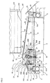
- a dispensing device includes juxtaposed conduits 1, fixed by their rear side on a chassis 6, each containing around thirty articles simply stacked; in the favorite mode, the items are 80 boxes from parallelepiped shape containing discs such CD, CD-Rom, CD-Worm, DVD, ...
- Each conduit 1 is formed from a folded sheet 100 to form four faces, the front face comprising a central opening 102 for easy insertion or remove boxes and at its base from a cutout 104 ( Figure 2) allowing translation out of the duct bottom case 82 only, both sides side and rear side having a fold at their base horizontal 103 carrying the lower housing 82.
- the device 10 notably includes a support made up of two parts 12, 13 leaning respectively on tubes 2, 3 using rollers 7 and connected by means such as tubes 14, 15 now the appropriate spacing.
- the support 12 has an inverted U profile, the support 13 in inverted L allowing installation, removal easy from the device 10 of the tubes 2, 3. It suffices in indeed, to position the device 10, to bring the support 13 around the tube 3 then deposit the support 12 on tube 2.
- these supports 12, 13 are made of plastic and fitted with wipers metal supported by the tubes 2, 3 which are conductors and respectively connected to the poles positive, negative of a power supply.
- the voltage is brought to the device 10 without the use of wires which is very advantageous for a mobile element thus made autonomous.
- the device 10 also includes a U-shaped movable frame 20 of which the lateral uprights 21 are provided with lugs 16 guided by tubes 14, 15 and support in rotation a control element 23 such as an axis associated with a drive element 22 such as a pulley.
- Pulley 22 is preferably notched and engaged with drive means such as a toothed belt continuous 24 (figure 3) guided by two pulleys identical notches 25 mounted in rotation on the supports 12, 13; the pulley 25 of the support 12 being a driving pulley, its axis 26 being moved in a way known, not shown, by a gear train controlled by a reversible electric motor for move the belt 24 in one direction opposite (arrows F, G).
- the pulley 25 of the support 13 is a simple return pulley whose axis is preferably mounted on springs to keep the belt 24 tense.
- the chassis 20 performs on the tubes 14, 15 back and forth between the supports 12, 13.
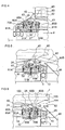
- Fingers 40, integral with the control element 23 are provided at their free end with a roulette 42 while their movement is limited by an element 28 such as a stud fixed to the pulley 22 and passing through an opening 30 (FIG. 7B) made in the lateral upright 21 of the chassis 20 facing over an area of about 90 degrees.
- This lateral upright 21 carries a plate 50, mounted in vertical translation thanks to nipples 51A, 51B forming part of said plate 50 and guided by grooves 27 made in the upright 21.
- this plate 50 carries a groove 56A, 56B, mirror each other to cooperate with fixed elements, such as axes 70A, 70B carried by the supports 12, 13.
- the plate 50 is subjected to the influence of a spring 52 pulling it upwards and door, trapped between it and the side upright 21, securing means such as two pawls 60A, 60B ( Figures 1A, 3, 7B) mounted in free rotation on each stud 51A, 51B.
- securing means such as two pawls 60A, 60B ( Figures 1A, 3, 7B) mounted in free rotation on each stud 51A, 51B.
- Each pawl has on the end protruding from the chassis 20 a groove 65A, 65B at the level of the groove 56A, 56B of the plate 50 for also cooperate with the axis 70A respectively 70B and is subjected to the action of a spring 61A, 61B attached to the frame 20 making it pivot downwards.
- the other end of the pawls 60A, 60B has a profile 63 cooperating with the stud 28 of the pulley 22.
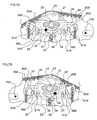
- the chassis 20 In the inactive position ( Figures 2, 3), the chassis 20 is secured to the support 12, the groove 65A of the pawl 60A trapping axis 70A. All the elements described above being located under the folds 103 of the conduits 1, in particular the fingers 40 which are at their low level, the device 10 can be freely translated on the tubes 2, 3, in a conventional way (cable, rack, ...), not shown, to be positioned under a duct 1.
- the motor driving the driving pulley 25 is put energized and drives it clockwise (Figure 2, arrow F).
- Belt 24 rotates the pulley 22 and the axis 23 clockwise, this which moves the nipple 28 from the right end of opening 30 towards its left end ( Figure 4).
- the stud 28 presses on the upper edge 54 of a cutout made in the plate 50 forcing it to descend and its groove 56A to imprison the axis 70A to secure the chassis 20 to support 12 (figure 2).
- the fingers 40 pivot to their upper level where they are substantially vertical ( Figure 4) and the nipple 28 acts on profile 63 of pawl 60A (FIG.
- the front 43 of fingers 40 acts on the lateral part rear of the lower case 82 to release it through the cutout 104, while the rollers 42 whose periphery slightly exceeds the level upper fingers 40 engage the penultimate 80 cases from the stack and hold it slightly separated from the last box 82 ( Figure 5), which greatly facilitates its release since it does not undergo more directly the weight of the other 80 and protects, significantly reducing the risk of abrasion, the adjacent surfaces of the housings 80, 82 and their packaging which, in general, is a thin film plastic.
- the chassis 20 When the chassis 20 approaches the support 13, the pawl 60B which is in the position shown in Figure 7A because subject only to the influence of spring 61B, approaches the axis 70B which does so pivot against spring 61B which results in the attachment of its groove 65B on the axis 70B and therefore securing the chassis 20 to the support 13 (FIG. 5), the lower case 82, disengaged from conduit 1, having terminated on a plate 86 for delivery to the user. Simultaneously, the chassis 20 actuates a switch magnetic (not shown) placed on the support 13 reversing the polarity of the motor driving the belt 24.
- a switch magnetic not shown
- the stud 28 releases the groove 65B from the axis 70B and allows the plate 50 to rise, which releases its groove 56B from the axis 70B ( Figure 6).
- the chassis 20 being free and the rotation of the pulley 22 stopped, the opening 30 blocking the stud 28, the belt 24 translates chassis 20 to support 12 (arrow G).
- the chassis 20 comes against the support, it activates a magnetic switch reversing the polarity of the motor and cutting off its power supply while the groove 65A of the pawl 60A secures it to axis 70A ( Figure 2).
- the device 10 is therefore ready for a new release cycle of housings.
- chassis 20 can be interrupted at any moment because during its reactivation it will continue its stroke until acting on one of the end switches race.
- the belt 24 being notched, the synchronization of the different phases is assured but we can use any other means, by example a chain.
- the device 10 of the invention can act on cases of different thicknesses thanks to the face before 43 fingers 40 which can optionally increase the height.
- the conduits 1 are connected to chassis 6 by eccentric cams having four positions so that the simple rotation of the cam adjusts each duct to the desired level for the type of boxes it stores.
- all the ducts are fixed at the same level and provided with the same opening 104 provided for thickest housings while shims are positioned on the folds 103 of the conduits 1 receiving thinner boxes to adapt the height of the opening 104 to the thickness of the type of housings stored.
Landscapes
- Physics & Mathematics (AREA)
- General Physics & Mathematics (AREA)
- Vending Machines For Individual Products (AREA)
- De-Stacking Of Articles (AREA)
- Warehouses Or Storage Devices (AREA)
- Automatic Analysis And Handling Materials Therefor (AREA)
- Packaging For Recording Disks (AREA)
- Control Of Vending Devices And Auxiliary Devices For Vending Devices (AREA)
Claims (15)
- Vorrichtung (10) für ein Ausgabegerät, das Lösen, Ausgabe von Artikeln (80, 82) gewährleistet, die in an einander gesetzten Schächten (1) gelagert sind, umfassend an ihrer Basis einen Ausschnitt (104) für den Durchtritt des unteren Artikels (82), wobei die Vorrichtung (10) auf einem Träger (12, 13) angebracht ist, der von Führungselementen (2, 3) getragen ist, die unter den Schächten (1) befestigt sind, um ihre Verschiebung zwischen Schächten (1) zu gewährleisten und umfassend einen Finger (40), der zwischen einem unteren Niveau, wo er von den Schächten (1) gelöst ist und einem oberen Niveau, wo er teilweise in einen Schacht (1) eingreift, verschiebbar ist, um den unteren Artikel (82) zu verschieben, Vorrichtung wobei der Finger (40) durch ein Gestell (20) getragen ist, das auf Führungsmitteln (14, 15) beweglich ist, die vom Träger (12, 13) getragen sind und mit Vorschubmitteln (24, 25, 26) in Verbindung, die bei einer Hin- und Herbewegung unter einem einzelnen Schacht (1) am Gestell (20) eine Verschiebung gewährleisten, wobei das Gestell (20) und/oder die Vorschubmittel (24, 25, 26) ein Steuerelement (23) tragen, das den Finger (40) je nach der Verschiebungsrichtung zwischen seinem unteren und oberen Niveau verschiebt.
- Vorrichtung (10) nach Anspruch 1, dadurch gekennzeichnet, dass das Steuerelement (23) des Fingers (40) mit einem Element (22) in Verbindung steht, das durch die Vorschubmittel (24, 25, 26) betätigt ist, um den Übergang des Fingers (40) zwischen seinem unteren und oberen Niveau in Abhängigkeit von der Verschiebungsrichtung der Vorschubmittel zu gewährleisten.
- Vorrichtung (10) nach Anspruch 2, dadurch gekennzeichnet, dass die Vorschubmittel (24, 25, 26) nacheinander auf den Finger (40) und das Gestell (20) einwirken.
- Vorrichtung (10) nach Anspruch 1, dadurch gekennzeichnet, dass das Steuerelement (23) vom Gestell (20) getragen ist.
- Vorrichtung (10) nach Anspruch 4, dadurch gekennzeichnet, dass das Gestell (20) Kopplungsmittel (60A, 60B) trägt, die mit dem Träger (12, 13) kooperieren, um das Gestell (20) damit zu koppeln.
- Vorrichtung (10) nach Anspruch 5, dadurch gekennzeichnet, dass der Träger (12, 13) aus zwei einzelnen Elementen gebildet ist, die an den Enden der Hin- und Herbewegung des Gestells (20) gelegen sind, wobei jedes Element ein festes Element (70A, 70B) trägt, das mit den Kopplungsmitteln (60A, 60B) kooperiert, die vom Gestell (20) getragen sind.
- Vorrichtung (10) nach einem der vorhergehenden Ansprüche, dadurch gekennzeichnet, dass die Vorschubmittel (24, 25, 26) umkehrbar sind.
- Vorrichtung (10) nach Anspruch 6, dadurch gekennzeichnet, dass das Steuerelement (23) den Finger (40) zwischen seinem unteren und oberen Niveau verschiebt, wenn die Kopplungsmittel (60A, 60B) das Gestell (20) an die Träger (12, 13) gekoppelt halten.
- Vorrichtung (10) nach einem der vorhergehenden Ansprüche, dadurch gekennzeichnet, dass das Steuerelement (23) des Fingers (40) Mittel (28, 30) umfasst, die seine Verschiebung begrenzen.
- Vorrichtung (10) nach Anspruch 9, dadurch gekennzeichnet, dass die Mittel, die die Verschiebung des Fingers (40) begrenzen, von einem Element (28) gebildet sind, das mit dem Steuerelement (23) verbunden ist und mit einer Öffnung (30) kooperiert, die im Gestell (20) ausgebildet ist.
- Vorrichtung (10) nach Anspruch 10, dadurch gekennzeichnet, dass der Finger (40) eine Rolle (42) trägt, die mit dem vorletzten Artikel (80) kooperiert, der in einem Schacht (1) gelegen ist, wobei die Rolle (42) und das Element (28) zu beiden Seiten des Steuerelements (23) gelegen sind.
- Vorrichtung (10) nach den Ansprüchen 5 und 9, dadurch gekennzeichnet, dass das Element (28), das die Verschiebung des Steuerelements (23) begrenzt, auf ein Profil (63) wirkt, das von den Kopplungsmitteln (60A, 60B) des Gestells (20) getragen ist.
- Vorrichtung (10) nach einem der vorhergehenden Ansprüche, dadurch gekennzeichnet, dass die Vorschubmittel (24, 25, 26) eingekerbt sind.
- Vorrichtung (10) nach einem der vorhergehenden Ansprüche, dadurch gekennzeichnet, dass die Führungsmittel (2, 3) mit Versorgungsanschlüssen verbunden sind, um der Vorrichtung (10) die notwendige Energie für ihre Funktion zuzuführen.
- Ausgabeeinheit für Artikel (80, 82), die in einer Reihe von Schächten (1) gelagert sind, wobei die Ausgabeeinheit Mittel umfasst, die eine Reihe von Schächten tragen, die an ihrer Basis einen Ausschnitt (104) umfassen, der den Durchtritt des Artikels (82) erlauben, der mindestens teilweise auf der Basis ruht, und ein System, das die Verschiebung einer Vorrichtung (10) zum Lösen und Ausgeben bezüglich der Schächte (1) der Reihe führt und die genannte Vorrichtung umfasst, wobei die genannte Vorrichtung (10) eine Vorrichtung nach einem der vorhergehenden Ansprüche ist.
Applications Claiming Priority (2)
| Application Number | Priority Date | Filing Date | Title |
|---|---|---|---|
| BE9700776A BE1011471A3 (fr) | 1997-09-24 | 1997-09-24 | Dispositif de degagement et distribution de boitiers, cassettes,... |
| BE9700776 | 1997-09-24 |
Publications (2)
| Publication Number | Publication Date |
|---|---|
| EP0905660A1 EP0905660A1 (de) | 1999-03-31 |
| EP0905660B1 true EP0905660B1 (de) | 2004-05-19 |
Family
ID=3890747
Family Applications (1)
| Application Number | Title | Priority Date | Filing Date |
|---|---|---|---|
| EP98870197A Expired - Lifetime EP0905660B1 (de) | 1997-09-24 | 1998-09-16 | Vorrichtung zum Lösen und Spenden von Artikeln |
Country Status (5)
| Country | Link |
|---|---|
| US (1) | US6126036A (de) |
| EP (1) | EP0905660B1 (de) |
| JP (1) | JPH11165877A (de) |
| BE (1) | BE1011471A3 (de) |
| DE (1) | DE69823942T2 (de) |
Families Citing this family (24)
| Publication number | Priority date | Publication date | Assignee | Title |
|---|---|---|---|---|
| BE1013576A3 (fr) | 2000-06-28 | 2002-04-02 | Staar Sa | Dispositif de saisie et delivrance d'objets. |
| DE10143802B4 (de) * | 2001-09-06 | 2017-03-09 | Leica Biosystems Nussloch Gmbh | Zuführeinrichtung für Kassetten und/oder Objektträgern für histologische Präparate in einem Drucksystem |
| US7234609B2 (en) * | 2004-04-15 | 2007-06-26 | Redbox Automated Retail, L.L.C. | Article dispensing system and method for same |
| US7584869B2 (en) | 2004-04-15 | 2009-09-08 | Redbox Automated Retail, Llc | Article dispensing system and method for same |
| US7447605B2 (en) | 2004-04-15 | 2008-11-04 | Redbox Automated Retail, Llc | System and method for calibrating a vending apparatus |
| US8060247B2 (en) | 2005-04-22 | 2011-11-15 | Redbox Automated Retail, Llc | System and method for communicating secondary vending options |
| CA2605550A1 (en) | 2005-04-22 | 2006-11-02 | Redbox Automated Retail, Llc | System and method for selling a rental media product |
| JP5306812B2 (ja) * | 2005-05-31 | 2013-10-02 | ビジックス インコーポレイテッド | キオスクから製品を送出するためのシステム、方法および装置 |
| US8768789B2 (en) | 2012-03-07 | 2014-07-01 | Redbox Automated Retail, Llc | System and method for optimizing utilization of inventory space for dispensable articles |
| US8712872B2 (en) | 2012-03-07 | 2014-04-29 | Redbox Automated Retail, Llc | System and method for optimizing utilization of inventory space for dispensable articles |
| US9886809B2 (en) | 2007-09-28 | 2018-02-06 | Redbox Automated Retail, Llc | Article dispensing machine and method for auditing inventory while article dispensing machine remains operational |
| KR100926154B1 (ko) * | 2008-05-08 | 2009-11-10 | 주식회사 메카시스 | 스트립 공급장치 |
| US8996162B2 (en) | 2009-09-05 | 2015-03-31 | Redbox Automated Retail, Llc | Article vending machine and method for exchanging an inoperable article for an operable article |
| US9104990B2 (en) | 2009-09-05 | 2015-08-11 | Redbox Automated Retail, Llc | Article vending machine and method for exchanging an inoperable article for an operable article |
| JP5480592B2 (ja) * | 2009-10-23 | 2014-04-23 | 日本電産サンキョー株式会社 | カード送出装置およびカード送出装置の制御方法 |
| US9569911B2 (en) | 2010-08-23 | 2017-02-14 | Redbox Automated Retail, Llc | Secondary media return system and method |
| US8538581B2 (en) | 2010-09-03 | 2013-09-17 | Redbox Automated Retail, Llc | Article vending machine and method for authenticating received articles |
| CA2838944A1 (en) | 2011-06-14 | 2012-12-20 | Redbox Automated Retail, Llc | System and method for substituting a media article with alternative media |
| US9495465B2 (en) | 2011-07-20 | 2016-11-15 | Redbox Automated Retail, Llc | System and method for providing the identification of geographically closest article dispensing machines |
| US9348822B2 (en) | 2011-08-02 | 2016-05-24 | Redbox Automated Retail, Llc | System and method for generating notifications related to new media |
| WO2013025392A2 (en) | 2011-08-12 | 2013-02-21 | Redbox Automated Retail, Llc | System and method for applying parental control limits from content providers to media content |
| US9747253B2 (en) | 2012-06-05 | 2017-08-29 | Redbox Automated Retail, Llc | System and method for simultaneous article retrieval and transaction validation |
| DE102017220271A1 (de) * | 2017-11-14 | 2019-05-16 | Gebr. Willach Gmbh | Warenzwischenlagervorrichtung |
| CN108765734B (zh) * | 2018-05-31 | 2020-11-03 | 深圳正品创想科技有限公司 | 一种混合货道以及无人售货柜 |
Family Cites Families (6)
| Publication number | Priority date | Publication date | Assignee | Title |
|---|---|---|---|---|
| US3893589A (en) * | 1973-03-23 | 1975-07-08 | Marrick Ind Inc | Vending machine with traveling release |
| FR2480101A1 (fr) * | 1980-04-10 | 1981-10-16 | Guigan Jean | Dispositif pour le stockage et la distribution automatique d'objets |
| GB2209331A (en) * | 1987-09-03 | 1989-05-10 | Atlas Equipment | Vending machine for hot food |
| DE3816028A1 (de) * | 1988-05-10 | 1989-11-23 | Dany S Snack Gmbh & Co | Ausgabe-automat fuer aufgebackene portionierte nahrungsmittel |
| FR2711116B1 (fr) * | 1993-10-11 | 1996-01-05 | Forenia Line Europ | Distributeur automatique d'objets. |
| FR2723656B1 (fr) * | 1994-08-10 | 1996-09-20 | Sagem | Distributeur de supports d'informations. |
-
1997
- 1997-09-24 BE BE9700776A patent/BE1011471A3/fr not_active IP Right Cessation
-
1998
- 1998-09-16 EP EP98870197A patent/EP0905660B1/de not_active Expired - Lifetime
- 1998-09-16 DE DE69823942T patent/DE69823942T2/de not_active Expired - Fee Related
- 1998-09-18 JP JP10282050A patent/JPH11165877A/ja active Pending
- 1998-09-18 US US09/156,653 patent/US6126036A/en not_active Expired - Fee Related
Also Published As
| Publication number | Publication date |
|---|---|
| BE1011471A3 (fr) | 1999-10-05 |
| DE69823942D1 (de) | 2004-06-24 |
| JPH11165877A (ja) | 1999-06-22 |
| US6126036A (en) | 2000-10-03 |
| DE69823942T2 (de) | 2005-05-19 |
| EP0905660A1 (de) | 1999-03-31 |
Similar Documents
| Publication | Publication Date | Title |
|---|---|---|
| EP0905660A1 (de) | Vorrichtung zum Lösen und Spenden von Artikeln | |
| CA1318610C (fr) | Dispositif de stockage et de distribution d'objets | |
| EP0454586B1 (de) | Präsentationsvorrichtung für in einer Reihe angeordnete Gegenstände | |
| CA2470457A1 (fr) | Procede et installation automatisee de stockage et de distribution d'objets ou articles divers | |
| FR2622554A1 (fr) | Magasin lineaire de stockage et de distribution automatique d'objets | |
| CA1164364A (fr) | Dispositif pour le stockage et la distribution automatique d'objets | |
| EP0850006A1 (de) | Automatische ausgabevorrichtung für beutel | |
| EP0632917B1 (de) | Automatische ausgeber für zeitungen u.d. mit auswahlmöglichkeiten | |
| EP0799776A1 (de) | Lagerregal | |
| EP2586326B1 (de) | Austeilvorrichtung für flache Produkte | |
| EP0364343B1 (de) | Verfahren und Vorrichtung zur automatischen Ausgabe von Waren, insbesondere von eventuell gewärmten Nahrungsmitteln | |
| EP1693317B1 (de) | Automatische Ausgabevorrichtung für Produkte | |
| FR2600991A1 (fr) | Distributeur d'elements minces empiles, muni d'un dispositif d'extraction de ces derniers, et boite-cartouche d'elements minces susceptible d'equiper un tel distributeur | |
| EP1970327A1 (de) | Stapel- und Beförderungsvorrichtung für Artikel | |
| WO1989012873A1 (fr) | Distributeur a prepaiement pour des articles conditionnes dans des emballages | |
| FR2638145A1 (fr) | Appareil de distribution automatique de documents | |
| FR2614714A1 (fr) | Distributeur automatique de produits allonges du type pains ou baguettes | |
| FR2650099A1 (fr) | Magasin a distribution automatique | |
| FR2670474A1 (fr) | Appareil permettant de distribuer un a un des articles stockes sous la forme d'un empilement. | |
| FR2692459A1 (fr) | Perfectionnements aux dispositifs de distribution de gobelets empilés. | |
| FR2955044A1 (fr) | Meuble de tri pour articles plats, notamment pour articles de presse | |
| EP0381914A2 (de) | Automatischer Spender für Säcke | |
| WO1993007075A1 (fr) | Dispositif de distribution automatique de produits | |
| FR2593792A1 (fr) | Distributeur d'elements minces et souples empiles, muni d'un dispositif d'extraction de ces derniers, et boite-cartouche destinee a equiper un tel distributeur | |
| FR2644441A1 (fr) | Dispositif de stockage et de distribution a l'unite d'objets tels qu'enveloppes, pochettes etc. |
Legal Events
| Date | Code | Title | Description |
|---|---|---|---|
| PUAI | Public reference made under article 153(3) epc to a published international application that has entered the european phase |
Free format text: ORIGINAL CODE: 0009012 |
|
| AK | Designated contracting states |
Kind code of ref document: A1 Designated state(s): BE CH DE ES FR GB IT LI NL PT |
|
| AX | Request for extension of the european patent |
Free format text: AL;LT;LV;MK;RO;SI |
|
| 17P | Request for examination filed |
Effective date: 19990507 |
|
| AKX | Designation fees paid |
Free format text: AT BE CH CY DE DK ES FI FR GB GR IE IT LI LU MC NL PT SE |
|
| RBV | Designated contracting states (corrected) |
Designated state(s): BE CH DE ES FR GB IT LI NL PT |
|
| RBV | Designated contracting states (corrected) |
Designated state(s): AT BE CH CY DE DK ES FI FR GB GR IE IT LI LU MC NL PT SE |
|
| RBV | Designated contracting states (corrected) |
Designated state(s): BE CH DE ES FR GB IT LI NL PT |
|
| 17Q | First examination report despatched |
Effective date: 20010517 |
|
| GRAP | Despatch of communication of intention to grant a patent |
Free format text: ORIGINAL CODE: EPIDOSNIGR1 |
|
| GRAS | Grant fee paid |
Free format text: ORIGINAL CODE: EPIDOSNIGR3 |
|
| GRAA | (expected) grant |
Free format text: ORIGINAL CODE: 0009210 |
|
| AK | Designated contracting states |
Kind code of ref document: B1 Designated state(s): BE CH DE ES FR GB IT LI NL PT |
|
| REG | Reference to a national code |
Ref country code: GB Ref legal event code: FG4D Free format text: NOT ENGLISH |
|
| REG | Reference to a national code |
Ref country code: CH Ref legal event code: EP |
|
| REG | Reference to a national code |
Ref country code: CH Ref legal event code: NV Representative=s name: PATENTANWAELTE SCHAAD, BALASS, MENZL & PARTNER AG |
|
| REF | Corresponds to: |
Ref document number: 69823942 Country of ref document: DE Date of ref document: 20040624 Kind code of ref document: P |
|
| GBT | Gb: translation of ep patent filed (gb section 77(6)(a)/1977) |
Effective date: 20040607 |
|
| PG25 | Lapsed in a contracting state [announced via postgrant information from national office to epo] |
Ref country code: ES Free format text: LAPSE BECAUSE OF FAILURE TO SUBMIT A TRANSLATION OF THE DESCRIPTION OR TO PAY THE FEE WITHIN THE PRESCRIBED TIME-LIMIT Effective date: 20040830 |
|
| PGFP | Annual fee paid to national office [announced via postgrant information from national office to epo] |
Ref country code: GB Payment date: 20040910 Year of fee payment: 7 |
|
| PGFP | Annual fee paid to national office [announced via postgrant information from national office to epo] |
Ref country code: CH Payment date: 20040920 Year of fee payment: 7 |
|
| PGFP | Annual fee paid to national office [announced via postgrant information from national office to epo] |
Ref country code: NL Payment date: 20040921 Year of fee payment: 7 |
|
| PLBE | No opposition filed within time limit |
Free format text: ORIGINAL CODE: 0009261 |
|
| STAA | Information on the status of an ep patent application or granted ep patent |
Free format text: STATUS: NO OPPOSITION FILED WITHIN TIME LIMIT |
|
| 26N | No opposition filed |
Effective date: 20050222 |
|
| PG25 | Lapsed in a contracting state [announced via postgrant information from national office to epo] |
Ref country code: IT Free format text: LAPSE BECAUSE OF NON-PAYMENT OF DUE FEES Effective date: 20050916 Ref country code: GB Free format text: LAPSE BECAUSE OF NON-PAYMENT OF DUE FEES Effective date: 20050916 |
|
| PGFP | Annual fee paid to national office [announced via postgrant information from national office to epo] |
Ref country code: BE Payment date: 20050920 Year of fee payment: 8 |
|
| PG25 | Lapsed in a contracting state [announced via postgrant information from national office to epo] |
Ref country code: LI Free format text: LAPSE BECAUSE OF NON-PAYMENT OF DUE FEES Effective date: 20050930 Ref country code: CH Free format text: LAPSE BECAUSE OF NON-PAYMENT OF DUE FEES Effective date: 20050930 |
|
| PG25 | Lapsed in a contracting state [announced via postgrant information from national office to epo] |
Ref country code: NL Free format text: LAPSE BECAUSE OF NON-PAYMENT OF DUE FEES Effective date: 20060401 |
|
| REG | Reference to a national code |
Ref country code: CH Ref legal event code: PL |
|
| GBPC | Gb: european patent ceased through non-payment of renewal fee |
Effective date: 20050916 |
|
| NLV4 | Nl: lapsed or anulled due to non-payment of the annual fee |
Effective date: 20060401 |
|
| PGFP | Annual fee paid to national office [announced via postgrant information from national office to epo] |
Ref country code: FR Payment date: 20060918 Year of fee payment: 9 |
|
| PGFP | Annual fee paid to national office [announced via postgrant information from national office to epo] |
Ref country code: DE Payment date: 20060926 Year of fee payment: 9 |
|
| PG25 | Lapsed in a contracting state [announced via postgrant information from national office to epo] |
Ref country code: BE Free format text: LAPSE BECAUSE OF NON-PAYMENT OF DUE FEES Effective date: 20060930 |
|
| BERE | Be: lapsed |
Owner name: S.A. *STAAR Effective date: 20060930 |
|
| PG25 | Lapsed in a contracting state [announced via postgrant information from national office to epo] |
Ref country code: PT Free format text: LAPSE BECAUSE OF NON-PAYMENT OF DUE FEES Effective date: 20041019 |
|
| PG25 | Lapsed in a contracting state [announced via postgrant information from national office to epo] |
Ref country code: DE Free format text: LAPSE BECAUSE OF NON-PAYMENT OF DUE FEES Effective date: 20080401 |
|
| REG | Reference to a national code |
Ref country code: FR Ref legal event code: ST Effective date: 20080531 |
|
| PG25 | Lapsed in a contracting state [announced via postgrant information from national office to epo] |
Ref country code: FR Free format text: LAPSE BECAUSE OF NON-PAYMENT OF DUE FEES Effective date: 20071001 |