EP0445088B1 - Grundplatte mit Kugelanschluss - Google Patents
Grundplatte mit Kugelanschluss Download PDFInfo
- Publication number
- EP0445088B1 EP0445088B1 EP91850004A EP91850004A EP0445088B1 EP 0445088 B1 EP0445088 B1 EP 0445088B1 EP 91850004 A EP91850004 A EP 91850004A EP 91850004 A EP91850004 A EP 91850004A EP 0445088 B1 EP0445088 B1 EP 0445088B1
- Authority
- EP
- European Patent Office
- Prior art keywords
- attachment
- spherical body
- nut
- pivotal
- attachment part
- Prior art date
- Legal status (The legal status is an assumption and is not a legal conclusion. Google has not performed a legal analysis and makes no representation as to the accuracy of the status listed.)
- Expired - Lifetime
Links
- 125000006850 spacer group Chemical group 0.000 claims description 11
- 239000000463 material Substances 0.000 claims description 9
- 229920001971 elastomer Polymers 0.000 claims description 4
- 239000000806 elastomer Substances 0.000 claims description 4
- 229920000728 polyester Polymers 0.000 claims description 4
- 238000004519 manufacturing process Methods 0.000 description 2
- 239000004952 Polyamide Substances 0.000 description 1
- 230000004048 modification Effects 0.000 description 1
- 238000012986 modification Methods 0.000 description 1
- 229920002647 polyamide Polymers 0.000 description 1
Images

Classifications
-
- F—MECHANICAL ENGINEERING; LIGHTING; HEATING; WEAPONS; BLASTING
- F16—ENGINEERING ELEMENTS AND UNITS; GENERAL MEASURES FOR PRODUCING AND MAINTAINING EFFECTIVE FUNCTIONING OF MACHINES OR INSTALLATIONS; THERMAL INSULATION IN GENERAL
- F16M—FRAMES, CASINGS OR BEDS OF ENGINES, MACHINES OR APPARATUS, NOT SPECIFIC TO ENGINES, MACHINES OR APPARATUS PROVIDED FOR ELSEWHERE; STANDS; SUPPORTS
- F16M11/00—Stands or trestles as supports for apparatus or articles placed thereon ; Stands for scientific apparatus such as gravitational force meters
- F16M11/02—Heads
- F16M11/04—Means for attachment of apparatus; Means allowing adjustment of the apparatus relatively to the stand
- F16M11/06—Means for attachment of apparatus; Means allowing adjustment of the apparatus relatively to the stand allowing pivoting
- F16M11/12—Means for attachment of apparatus; Means allowing adjustment of the apparatus relatively to the stand allowing pivoting in more than one direction
- F16M11/14—Means for attachment of apparatus; Means allowing adjustment of the apparatus relatively to the stand allowing pivoting in more than one direction with ball-joint
-
- F—MECHANICAL ENGINEERING; LIGHTING; HEATING; WEAPONS; BLASTING
- F16—ENGINEERING ELEMENTS AND UNITS; GENERAL MEASURES FOR PRODUCING AND MAINTAINING EFFECTIVE FUNCTIONING OF MACHINES OR INSTALLATIONS; THERMAL INSULATION IN GENERAL
- F16M—FRAMES, CASINGS OR BEDS OF ENGINES, MACHINES OR APPARATUS, NOT SPECIFIC TO ENGINES, MACHINES OR APPARATUS PROVIDED FOR ELSEWHERE; STANDS; SUPPORTS
- F16M2200/00—Details of stands or supports
- F16M2200/02—Locking means
- F16M2200/021—Locking means for rotational movement
- F16M2200/022—Locking means for rotational movement by friction
-
- Y—GENERAL TAGGING OF NEW TECHNOLOGICAL DEVELOPMENTS; GENERAL TAGGING OF CROSS-SECTIONAL TECHNOLOGIES SPANNING OVER SEVERAL SECTIONS OF THE IPC; TECHNICAL SUBJECTS COVERED BY FORMER USPC CROSS-REFERENCE ART COLLECTIONS [XRACs] AND DIGESTS
- Y10—TECHNICAL SUBJECTS COVERED BY FORMER USPC
- Y10T—TECHNICAL SUBJECTS COVERED BY FORMER US CLASSIFICATION
- Y10T403/00—Joints and connections
- Y10T403/32—Articulated members
- Y10T403/32254—Lockable at fixed position
- Y10T403/32262—At selected angle
- Y10T403/32311—Ball and socket
-
- Y—GENERAL TAGGING OF NEW TECHNOLOGICAL DEVELOPMENTS; GENERAL TAGGING OF CROSS-SECTIONAL TECHNOLOGIES SPANNING OVER SEVERAL SECTIONS OF THE IPC; TECHNICAL SUBJECTS COVERED BY FORMER USPC CROSS-REFERENCE ART COLLECTIONS [XRACs] AND DIGESTS
- Y10—TECHNICAL SUBJECTS COVERED BY FORMER USPC
- Y10T—TECHNICAL SUBJECTS COVERED BY FORMER US CLASSIFICATION
- Y10T403/00—Joints and connections
- Y10T403/32—Articulated members
- Y10T403/32549—Articulated members including limit means
- Y10T403/32557—Articulated members including limit means for pivotal motion
- Y10T403/32565—Ball and socket with restricted movement about one axis
Definitions
- the present invention relates to a pivotal attachment means for attaching an object to a supporting surface, said attachment means comprising a lower part which is intended to be fastened to the supporting surface and which includes an outwardly projecting part having a central, dished recess and a surrounding screw thread, and an upper part which includes an attachment plate intended to be fastened to the object, a spacer bolt which projects out from the attachment plate, an attachment nut which is placed around the spacer bolt and which is screwed firmly to the outwardly projecting part on the lower part of said pivotal attachment and provided with an inwardly projecting edge having a dish-shaped chamfer, and further comprising a spherical body which is attached to the outer end of the spacer bolt and which is located in the space between the lower part of said attachment and the attachment nut.
- the preamble of claim 1 defines such a pivotal attachment means.
- pivotal attachments of this kind for the purpose of attaching an object to a supporting surface while enabling the object to be moved to different positional settings and angular positions in relation to the supporting surface.
- the known attachments are encumbered with certain drawbacks. For instance, it is necessary with these attachments to screw down the nut very tightly in order to achieve a stable attachment, i.e. in order to ensure that the object will not move out of its set position.
- US Patent No. 2 861 501 discloses a pivotal attachment means of the above-mentioned kind for attaching an object to a supporting surface.
- the attachment means comprises a lower attachment part intended for attachment to a supporting surface, an upper attachment part intended to be fastened to the object, a spherical body, a spacer bolt projecting out from the spherical body, and a nut placed around the spacer bolt.
- the lower attachment part comprises an outwardly projecting part having a central dished recess and a surrounding screw thread.
- the nut is provided with an inwardly projecting edge provided with a dish-shaped chamfer or bevel, and is screwed firmly to the outwardly projecting part of said lower attachment part, the spherical body being accomodated in the space between the lower attachment part and the attachment nut.
- This attachment means suffers from the same drawbacks as mentioned above.
- the object of the present invention is to overcome the drawbacks associated with known pivotal attachment means as defined in the preamble of claim 1 and to provide a pivotal attachment means which can be readily adjusted to different angular positions and setting positions and with which the risk of the spherical body being clamped firmly in the recess is minimized. This is achieved by providing the dished recess of the lower part of the attachment means with wedge-shaped projections against which the spherical body rests, and by manufacturing the spherical body from an inelastic material which is softer than the material from which said lower attachment part and said nut are made.
- the spherical body is preferably manufactured from a polyester elastomer.
- the attachment nut is advantageously provided with radially projecting arms which function as a handgrip.
- the inventive pivotal attachment means provides several advantages.
- One advantage is that the nut need not be tightened with unreasonable force while nevertheless providing a sufficiently stable attachment without disturbing the setting of the object. Because the spherical body is made of a softer material than the nut and the lower attachment part, the wedge-shaped projections will enter the spherical body and lock the same.
- Another advantage is that there is no risk of the spherical body wedging in the recess, therewith enabling the set position of the object to be readily changed.
- the advantage afforded by manufacturing the spherical body from a polyester elastomer is that this material is sufficiently soft to enable the spherical body to be affixed over the wedges and is, at the same time, so hard that the spherical body need not be elastic, which affords stable attachment of the object in the absence of swinging.
- the nut is provided with outwardly projecting arms which function as a handgrip, the nut can be readily tightened by hand, without requiring tools herefor.
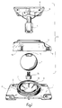
- Figure 1 is a perspective, exploded view of the components of a pivotal attachment means according to the invention.
- Figure 2 is a sectional view of the pivotal attachment shown in Figure 1 when assembled.
- FIG 1 is a perspective view of the components of an inventive pivotal attachment means.
- the attachment comprises a lower part 1 which is intended to be secured to a supporting surface, for instance by means of screws which pass through screw holes 2, and an upper part 3 which includes an attachment plate 4, a spacer bolt 5, an attachment nut 6 and a spherical body 7.
- the attachment plate 4 is intended to be secured to an object in some suitable manner, for instance with the aid of screws passing through screw holes 8.
- the lower part includes an outwardly projecting or upstanding part 9 which is configured with a central dished recess 10.
- the outer surface of the projecting part 9 has formed thereon an external screw thread 11 for engagement with a corresponding screw thread on the nut 6.
- the radius of the recess 10 is somewhat larger than the radius of the spherical body 7 and is provided with vertically extending wedge-shaped projections 12, which lie against the spherical body.
- the spacer bolt 5 is moulded in the attachment plate 4 so that it cannot be twisted relative to the plate, or is attached to said plate in some other suitable manner.
- the outer end of the spacer bolt has an hexagonal configuration, or some other non-circular configuration, and is attached in the spherical body 7 in a corresponding cavity 13 therein, with the aid of a screw 14 accommodated in a recessed hole 15 in the spherical body, as clearly shown in Figure 2.
- the nut 6 is passed over the bolt 5, prior to securing the spherical body 7 on said bolt.
- the nut 6 is provided with an edge 16 which projects out over the spherical body and which is provided with a dish-shaped chamfer or bevel 17 which lies against the spherical body and holds said body firm.
- the nut is also provided with radially and outwardly projecting arms 18 which function as a handgrip when tightening and loosening the nut.
- the edge 16 presses the spherical body 7 into abutment with the projections 12 in the recess 9 of the lower attachment part, therewith causing the projections to penetrate into the spherical body and positively lock said body in an adjusted position, as illustrated in Figure 2.
- the wedge-shaped projections also function to ensure that the spherical body will not fasten in the lower attachment part, therewith enabling the pivotal attachment to be readily loosened in order to change the setting of said object.
- the spherical body 7 is configured from a material which is softer than the material from which the lower attachment part 1 and the attachment nut 6 are made, for instance, of a polyester elastomer, which is sufficiently soft to permit the projections to penetrate into the spherical body but, at the same time, sufficiently rigid to ensure that the pivotal attachment will not swing when load is applied.
- the lower attachment part and the attachment nut are preferably made of a polyamide material, which is sufficiently hard to provide satisfactory strength to the pivotal attachment.
Landscapes
- Engineering & Computer Science (AREA)
- General Engineering & Computer Science (AREA)
- Mechanical Engineering (AREA)
- Pivots And Pivotal Connections (AREA)
- Bolts, Nuts, And Washers (AREA)
Claims (3)
- Verschwenkbare Befestigungsvorrichtung zum Anbringen eines Gegenstandes auf einer Tragfläche mit einem unteren Befestigungsteil (1), das zur Befestigung an der Tragfläche bestimmt ist und das ein nach außen vorspringendes Teil (9) aufweist, das eine mittige Vertiefung (10) hat sowie ein diese umgebendes Außengewinde (11) und mit einem oberen Befestigungsteil (3), das eine Befestigungsplatte (4) hat, die dazu bestimmt ist, am Gegenstand befestigt zu werden, einem Abstandsbolzen (5), der aus der Befestigungsplatte vorsteht, einer Mutter (6), die um den Abstandsbolzen herum angeordnet ist und die fest auf den nach außen vorspringenden Teil des unteren Befestigungsteiles aufgeschraubt werden kann und die mit einer nach innen vorstehenden Kante (16) versehen ist, die ihrerseits mit einer tellerförmigen Abschrägung (17) versehen ist und schließlich mit einem kugelförmigen Körper (7), der am äußeren Ende des Abstandsbolzens angebracht ist und der in dem Raum zwischen dem unteren Befestigungsteil und der Befestigungsmutter liegt,
dadurch gekennzeichnet, daß
der Radius der Vertiefung (10) des unteren Befestigungsteils (1) etwas größer ist als der Radius des kugelförmigen Körpers (7);
die Vertiefung (10) mit keilförmigen Vorsprüngen (12) ausgebildet ist, gegen die der kugelförmige Körper (7) anliegt; und
daß der kugelförmige Körper aus einem Material besteht, das weicher ist als das Material, aus dem das untere Befestigungsteil und die Mutter hergestellt sind. - Verschwenkbare Befestigungsvorrichtung nach Anspruch 1, dadurch gekennzeichnet, daß der kugelförmige Körper (7) aus einem Polyester-Elastomer besteht.
- Verschwenkbare Befestigungsvorrichtung nach Anspruch 1, dadurch gekennzeichnet, daß die Mutter (6) mit radial nach außen vorspringenden Armen versehen ist, die als Handgriff wirken.
Applications Claiming Priority (2)
| Application Number | Priority Date | Filing Date | Title |
|---|---|---|---|
| SE9000517 | 1990-02-13 | ||
| SE9000517A SE465534B (sv) | 1990-02-13 | 1990-02-13 | Ledat faeste foer att faesta ett foeremaal paa ett underlag |
Publications (2)
| Publication Number | Publication Date |
|---|---|
| EP0445088A1 EP0445088A1 (de) | 1991-09-04 |
| EP0445088B1 true EP0445088B1 (de) | 1995-04-26 |
Family
ID=20378548
Family Applications (1)
| Application Number | Title | Priority Date | Filing Date |
|---|---|---|---|
| EP91850004A Expired - Lifetime EP0445088B1 (de) | 1990-02-13 | 1991-01-09 | Grundplatte mit Kugelanschluss |
Country Status (8)
| Country | Link |
|---|---|
| US (1) | US5071279A (de) |
| EP (1) | EP0445088B1 (de) |
| JP (1) | JP3071836B2 (de) |
| AU (1) | AU636707B2 (de) |
| CA (1) | CA2036246C (de) |
| DE (1) | DE69109158T2 (de) |
| ES (1) | ES2074254T3 (de) |
| SE (1) | SE465534B (de) |
Families Citing this family (55)
| Publication number | Priority date | Publication date | Assignee | Title |
|---|---|---|---|---|
| SE465534B (sv) | 1990-02-13 | 1991-09-23 | Ericsson Telefon Ab L M | Ledat faeste foer att faesta ett foeremaal paa ett underlag |
| DE4124232A1 (de) * | 1991-07-22 | 1993-01-28 | Bosch Gmbh Robert | Handkreissaege, insbesondere tauchsaege |
| DE4211301A1 (de) * | 1992-04-05 | 1993-10-07 | Heinz Mack | Verriegelungsvorrichtung für einen Artikulator |
| US5280871A (en) * | 1992-09-30 | 1994-01-25 | Chuang Ching Pao | Securing base |
| US5845885A (en) | 1993-12-14 | 1998-12-08 | National Products, Inc. | Universally positionable mounting device |
| USRE42060E1 (en) | 1993-12-14 | 2011-01-25 | National Products, Inc. | Universally positionable mounting device |
| FR2714563B1 (fr) * | 1993-12-23 | 1996-01-19 | Alcatel Mobile Comm France | Système de fixation pour microphone. |
| SE502673C2 (sv) * | 1994-10-14 | 1995-12-04 | Hansson Erik G | Ställdon för inställning i rymden av ett första föremål i förhållande till ett andra, fast föremål |
| GB2296288A (en) * | 1994-12-16 | 1996-06-26 | Kenex | Mount for a radiation shield |
| US6581892B2 (en) | 2001-05-14 | 2003-06-24 | Jeffrey D. Carnevali | Geodesic mounting apparatus |
| US6561476B2 (en) | 2001-05-14 | 2003-05-13 | Jeffrey D. Carnevali | Positively-positionable mounting apparatus |
| US7101135B2 (en) * | 2002-07-19 | 2006-09-05 | Bell Helicopter Textron, Inc. | Self-aligning nut plate |
| US6913229B2 (en) * | 2003-02-03 | 2005-07-05 | Unitrend, Inc. | Wire management system |
| US7261265B2 (en) * | 2003-06-20 | 2007-08-28 | Vantage Point Products Corp. | System for mounting a flat panel display |
| US7090181B2 (en) * | 2003-10-31 | 2006-08-15 | Gamber Johnson Llc | Ball and socket mounting assembly |
| US7351899B2 (en) * | 2005-03-15 | 2008-04-01 | Think Peak, Inc. | Quick action drum lug assembly and method |
| TW200911583A (en) * | 2007-09-14 | 2009-03-16 | Mitac Int Corp | Support seat for electronic device |
| US8413398B1 (en) * | 2008-06-20 | 2013-04-09 | 3Form, Inc. | Ball pivot assemblies and systems and methods incorporating the same |
| TWM369736U (en) * | 2009-07-01 | 2009-12-01 | Huang-Kai Liang | Structure of shower curtain rack |
| CN101994896A (zh) * | 2009-08-17 | 2011-03-30 | 鸿富锦精密工业(深圳)有限公司 | 连接装置 |
| FR3015624B1 (fr) | 2013-12-23 | 2016-06-10 | Inst Nat De Rech En Sciences Et Tech Pour L'environnement Et L'agriculture (Irstea) | Dispositif de fixation d'un element allonge |
| JP6278266B2 (ja) * | 2014-04-23 | 2018-02-14 | アーキヤマデ株式会社 | 太陽光モジュールの設置用ユニバーサル・リテンションボルトユニットの製造法 |
| US9709356B1 (en) * | 2014-05-06 | 2017-07-18 | Tja Design Llc | Multi-axis firearm foregrip |
| USD809053S1 (en) * | 2016-02-27 | 2018-01-30 | Jeffrey D. Carnevali | Adapter base with ball mount |
| USD814549S1 (en) * | 2016-02-27 | 2018-04-03 | Jeffrey D. Carnevali | Adapter base with ball mount |
| GB201611655D0 (en) * | 2016-07-04 | 2016-08-17 | 3M Innovative Properties Co | Article mounting device |
| USD803674S1 (en) | 2016-08-04 | 2017-11-28 | National Products, Inc. | Mounting device |
| USD839796S1 (en) * | 2017-03-07 | 2019-02-05 | Nan-Chang Chiu | Bearer container for a multi-axis aircraft |
| US10527219B2 (en) | 2017-06-02 | 2020-01-07 | National Products, Inc. | Mounting track for retaining a mount assembly |
| US10982807B2 (en) | 2017-06-02 | 2021-04-20 | National Products, Inc. | Handle with mounting track for receiving a mount assembly |
| US10155306B1 (en) | 2017-06-02 | 2018-12-18 | National Products, Inc. | Handle with mounting track for receiving a mount assembly |
| US11085579B2 (en) | 2017-06-02 | 2021-08-10 | National Products, Inc. | Mounting track for retaining a mount assembly |
| US10429002B2 (en) | 2017-06-19 | 2019-10-01 | National Products, Inc. | Top-loading mounting track for receiving a mount assembly |
| US10378690B2 (en) | 2017-07-14 | 2019-08-13 | National Products, Inc. | Systems and methods for making and using mounts for receiving objects and coupling to surfaces |
| US10448626B2 (en) | 2017-07-14 | 2019-10-22 | National Products, Inc. | Fishing rod holder with a top mount receptacle for receiving a device mount |
| NZ735256A (en) * | 2017-09-05 | 2018-06-29 | Railblaza Ltd | An extender for holding accessories |
| US10434353B1 (en) * | 2017-10-26 | 2019-10-08 | Thomas S. Fabbri | Portable exercise ball-and-stick apparatus |
| US10473150B2 (en) | 2018-04-17 | 2019-11-12 | National Products, Inc. | Mounting arrangement for attachment to device sockets and methods of making and using |
| USD891906S1 (en) | 2019-01-07 | 2020-08-04 | National Products, Inc. | Mounting device |
| USD899222S1 (en) | 2019-01-07 | 2020-10-20 | National Products, Inc. | Mounting device with attached ball |
| USD891905S1 (en) | 2019-01-07 | 2020-08-04 | National Products, Inc. | Mounting device with ball |
| US11149943B2 (en) * | 2019-03-29 | 2021-10-19 | Radoslaw K. BUCHOWIECKI | Tool for releasably holding a torch |
| US11547896B2 (en) * | 2019-10-21 | 2023-01-10 | Sheri Elizabeth Roberts | Multifunctional mobile exercise device for the upper extremity |
| US11635155B2 (en) | 2020-05-08 | 2023-04-25 | National Products, Inc. | Adapter for attachment to a track or other surface or for receiving devices having different shaft spline arrangements |
| US12158179B1 (en) * | 2020-11-23 | 2024-12-03 | Yakattack Llc | Ball mount and accessory mounting track and tee-bolt for use therewith |
| US12161905B2 (en) | 2022-09-09 | 2024-12-10 | Custom Product Innovations, Inc. | Weightlifting accessory |
| USD1061763S1 (en) | 2023-01-20 | 2025-02-11 | Tracy Anderson Mind And Body, Llc | Puck |
| USD1061753S1 (en) | 2023-01-20 | 2025-02-11 | Tracy Anderson Mind And Body, Llc | Staff |
| USD1092231S1 (en) | 2023-01-20 | 2025-09-09 | Tracy Anderson Mind And Body, Llc | Box |
| USD1043866S1 (en) | 2023-01-20 | 2024-09-24 | Tracy Anderson Mind And Body, Llc | Weight |
| WO2024076706A1 (en) * | 2022-10-06 | 2024-04-11 | Tracy Anderson Mind And Body, Llc | Anchored staff |
| US12115919B2 (en) * | 2022-10-14 | 2024-10-15 | Yonder Fund Llc | Mounting system with anti-rotation features for supporting an electronic device |
| US11648452B1 (en) * | 2022-11-25 | 2023-05-16 | Xiamen Shouxi Sports Technology Co., Ltd | Auxiliary tool for barbells and anti-slip method for barbells during use |
| CN219432941U (zh) * | 2023-02-23 | 2023-07-28 | 昆山联滔电子有限公司 | 万向接头 |
| US12305799B2 (en) | 2023-04-19 | 2025-05-20 | National Products, Inc. | Vibration dampening mounts and methods of making and using |
Citations (3)
| Publication number | Priority date | Publication date | Assignee | Title |
|---|---|---|---|---|
| US2861501A (en) * | 1954-07-09 | 1958-11-25 | George P Strelakos | Portable light reflector with magnifying glass |
| CH643904A5 (en) * | 1979-09-26 | 1984-06-29 | Erwin Mueller | Stand for a traffic guiding element which is to be mounted on or next to a traffic area |
| EP0201817A2 (de) * | 1985-05-11 | 1986-11-20 | Reinhold Reiling | Universalhalter |
Family Cites Families (6)
| Publication number | Priority date | Publication date | Assignee | Title |
|---|---|---|---|---|
| US1934223A (en) * | 1931-11-16 | 1933-11-07 | Noblitt Sparks Ind Inc | Mounting for rear-vision mirrors |
| FR953685A (fr) * | 1947-10-02 | 1949-12-12 | Rotule pour appareil photographique | |
| US4019710A (en) * | 1976-02-11 | 1977-04-26 | Chadwell O'Connor | Instrument support socket |
| IL80661A (en) * | 1985-11-29 | 1991-07-18 | Jaquet Orthopedie | Device for positioning and securing a part having circular regions |
| GB2213369A (en) * | 1987-12-09 | 1989-08-16 | Okabe Kinzoku Kogyo Gomei Kais | Variable angle supporting device |
| SE465534B (sv) | 1990-02-13 | 1991-09-23 | Ericsson Telefon Ab L M | Ledat faeste foer att faesta ett foeremaal paa ett underlag |
-
1990
- 1990-02-13 SE SE9000517A patent/SE465534B/sv not_active IP Right Cessation
-
1991
- 1991-01-09 EP EP91850004A patent/EP0445088B1/de not_active Expired - Lifetime
- 1991-01-09 ES ES91850004T patent/ES2074254T3/es not_active Expired - Lifetime
- 1991-01-09 DE DE69109158T patent/DE69109158T2/de not_active Expired - Fee Related
- 1991-02-07 JP JP3016127A patent/JP3071836B2/ja not_active Expired - Fee Related
- 1991-02-12 AU AU70957/91A patent/AU636707B2/en not_active Ceased
- 1991-02-12 US US07/654,017 patent/US5071279A/en not_active Expired - Lifetime
- 1991-02-13 CA CA002036246A patent/CA2036246C/en not_active Expired - Fee Related
Patent Citations (3)
| Publication number | Priority date | Publication date | Assignee | Title |
|---|---|---|---|---|
| US2861501A (en) * | 1954-07-09 | 1958-11-25 | George P Strelakos | Portable light reflector with magnifying glass |
| CH643904A5 (en) * | 1979-09-26 | 1984-06-29 | Erwin Mueller | Stand for a traffic guiding element which is to be mounted on or next to a traffic area |
| EP0201817A2 (de) * | 1985-05-11 | 1986-11-20 | Reinhold Reiling | Universalhalter |
Also Published As
| Publication number | Publication date |
|---|---|
| DE69109158D1 (de) | 1995-06-01 |
| SE465534B (sv) | 1991-09-23 |
| ES2074254T3 (es) | 1995-09-01 |
| CA2036246A1 (en) | 1991-08-14 |
| SE9000517L (sv) | 1991-08-14 |
| AU636707B2 (en) | 1993-05-06 |
| CA2036246C (en) | 1998-08-18 |
| AU7095791A (en) | 1991-08-15 |
| DE69109158T2 (de) | 1995-09-21 |
| EP0445088A1 (de) | 1991-09-04 |
| SE9000517D0 (sv) | 1990-02-13 |
| JPH04211714A (ja) | 1992-08-03 |
| JP3071836B2 (ja) | 2000-07-31 |
| US5071279A (en) | 1991-12-10 |
Similar Documents
| Publication | Publication Date | Title |
|---|---|---|
| EP0445088B1 (de) | Grundplatte mit Kugelanschluss | |
| US6126355A (en) | Fastener for adjustable support device | |
| US4632356A (en) | Vertically adjustable shock-absorbing mounting device | |
| US20040260283A1 (en) | Multi-axis spinal fixation device | |
| US8210581B2 (en) | Door handle attachment fixture | |
| CA2258134A1 (en) | Disk locking device | |
| JPH03103613A (ja) | 組立プレート用締付ネジ | |
| EP0329443B1 (de) | Klemmen und Klemm-Montage | |
| US6089807A (en) | Bolt-and-nut joint | |
| US4105058A (en) | Screw locking arrangement | |
| US5169116A (en) | Mounting lug for television or similar appliance | |
| US7118316B2 (en) | Fixing element for inserting into a longitudinal cavity of a carrier plate | |
| US4043594A (en) | Adjustable chair rest member | |
| JP2004050402A (ja) | フックねじドライバー | |
| US3944228A (en) | Curling stone washer and handle assembly | |
| JP2571142Y2 (ja) | フロアパネルの支持脚 | |
| JP3237687B2 (ja) | ボルトねじの緩み止め装置 | |
| JPH0231866Y2 (de) | ||
| JP2575225Y2 (ja) | ナット | |
| JPH036221Y2 (de) | ||
| GB2252355A (en) | Clamp assemblies | |
| JPH0410458Y2 (de) | ||
| JPH0729918Y2 (ja) | 浴槽の把手の取り付け構造 | |
| JPS6312880Y2 (de) | ||
| JPH05187421A (ja) | ボルト・ナットユニット |
Legal Events
| Date | Code | Title | Description |
|---|---|---|---|
| PUAI | Public reference made under article 153(3) epc to a published international application that has entered the european phase |
Free format text: ORIGINAL CODE: 0009012 |
|
| AK | Designated contracting states |
Kind code of ref document: A1 Designated state(s): DE ES FR GB IT NL |
|
| 17P | Request for examination filed |
Effective date: 19920121 |
|
| 17Q | First examination report despatched |
Effective date: 19930615 |
|
| GRAA | (expected) grant |
Free format text: ORIGINAL CODE: 0009210 |
|
| AK | Designated contracting states |
Kind code of ref document: B1 Designated state(s): DE ES FR GB IT NL |
|
| REF | Corresponds to: |
Ref document number: 69109158 Country of ref document: DE Date of ref document: 19950601 |
|
| ITF | It: translation for a ep patent filed | ||
| ET | Fr: translation filed | ||
| REG | Reference to a national code |
Ref country code: ES Ref legal event code: FG2A Ref document number: 2074254 Country of ref document: ES Kind code of ref document: T3 |
|
| PLBE | No opposition filed within time limit |
Free format text: ORIGINAL CODE: 0009261 |
|
| STAA | Information on the status of an ep patent application or granted ep patent |
Free format text: STATUS: NO OPPOSITION FILED WITHIN TIME LIMIT |
|
| 26N | No opposition filed | ||
| REG | Reference to a national code |
Ref country code: GB Ref legal event code: IF02 |
|
| PGFP | Annual fee paid to national office [announced via postgrant information from national office to epo] |
Ref country code: NL Payment date: 20051216 Year of fee payment: 16 |
|
| PGFP | Annual fee paid to national office [announced via postgrant information from national office to epo] |
Ref country code: FR Payment date: 20060117 Year of fee payment: 16 |
|
| PGFP | Annual fee paid to national office [announced via postgrant information from national office to epo] |
Ref country code: ES Payment date: 20060126 Year of fee payment: 16 |
|
| NLV4 | Nl: lapsed or anulled due to non-payment of the annual fee |
Effective date: 20070801 |
|
| REG | Reference to a national code |
Ref country code: FR Ref legal event code: ST Effective date: 20070930 |
|
| PG25 | Lapsed in a contracting state [announced via postgrant information from national office to epo] |
Ref country code: NL Free format text: LAPSE BECAUSE OF NON-PAYMENT OF DUE FEES Effective date: 20070801 |
|
| REG | Reference to a national code |
Ref country code: ES Ref legal event code: FD2A Effective date: 20070110 |
|
| PG25 | Lapsed in a contracting state [announced via postgrant information from national office to epo] |
Ref country code: FR Free format text: LAPSE BECAUSE OF NON-PAYMENT OF DUE FEES Effective date: 20070131 |
|
| PGFP | Annual fee paid to national office [announced via postgrant information from national office to epo] |
Ref country code: IT Payment date: 20080130 Year of fee payment: 18 |
|
| PG25 | Lapsed in a contracting state [announced via postgrant information from national office to epo] |
Ref country code: ES Free format text: LAPSE BECAUSE OF NON-PAYMENT OF DUE FEES Effective date: 20070110 |
|
| PGFP | Annual fee paid to national office [announced via postgrant information from national office to epo] |
Ref country code: DE Payment date: 20090302 Year of fee payment: 19 |
|
| PGFP | Annual fee paid to national office [announced via postgrant information from national office to epo] |
Ref country code: GB Payment date: 20090129 Year of fee payment: 19 |
|
| GBPC | Gb: european patent ceased through non-payment of renewal fee |
Effective date: 20100109 |
|
| PG25 | Lapsed in a contracting state [announced via postgrant information from national office to epo] |
Ref country code: DE Free format text: LAPSE BECAUSE OF NON-PAYMENT OF DUE FEES Effective date: 20100803 |
|
| PG25 | Lapsed in a contracting state [announced via postgrant information from national office to epo] |
Ref country code: GB Free format text: LAPSE BECAUSE OF NON-PAYMENT OF DUE FEES Effective date: 20100109 |
|
| PG25 | Lapsed in a contracting state [announced via postgrant information from national office to epo] |
Ref country code: IT Free format text: LAPSE BECAUSE OF NON-PAYMENT OF DUE FEES Effective date: 20090109 |