EP0445341A1 - Flüssigkeitsdichter Industriefussbodenbelag - Google Patents
Flüssigkeitsdichter Industriefussbodenbelag Download PDFInfo
- Publication number
- EP0445341A1 EP0445341A1 EP90104560A EP90104560A EP0445341A1 EP 0445341 A1 EP0445341 A1 EP 0445341A1 EP 90104560 A EP90104560 A EP 90104560A EP 90104560 A EP90104560 A EP 90104560A EP 0445341 A1 EP0445341 A1 EP 0445341A1
- Authority
- EP
- European Patent Office
- Prior art keywords
- floor covering
- sealing
- liquid
- covering according
- joint
- Prior art date
- Legal status (The legal status is an assumption and is not a legal conclusion. Google has not performed a legal analysis and makes no representation as to the accuracy of the status listed.)
- Granted
Links
Images
Classifications
-
- E—FIXED CONSTRUCTIONS
- E01—CONSTRUCTION OF ROADS, RAILWAYS, OR BRIDGES
- E01C—CONSTRUCTION OF, OR SURFACES FOR, ROADS, SPORTS GROUNDS, OR THE LIKE; MACHINES OR AUXILIARY TOOLS FOR CONSTRUCTION OR REPAIR
- E01C11/00—Details of pavings
- E01C11/02—Arrangement or construction of joints; Methods of making joints; Packing for joints
- E01C11/04—Arrangement or construction of joints; Methods of making joints; Packing for joints for cement concrete paving
- E01C11/10—Packing of plastic or elastic materials, e.g. wood, resin
-
- E—FIXED CONSTRUCTIONS
- E04—BUILDING
- E04F—FINISHING WORK ON BUILDINGS, e.g. STAIRS, FLOORS
- E04F15/00—Flooring
- E04F15/02—Flooring or floor layers composed of a number of similar elements
- E04F15/02005—Construction of joints, e.g. dividing strips
- E04F15/02016—Construction of joints, e.g. dividing strips with sealing elements between flooring elements
Definitions
- the invention relates to a liquid-tight industrial floor covering, consisting of concrete floor slabs, which are kept at a distance from one another with the aid of intermediate spacers with the formation of gaps and above the spacers at their end faces have a longitudinal chamber arranged at a distance from the top of the plate, and from one into the Joints introduced joint seal with an expandable sealing strand running in the longitudinal cavities of adjacent floor panels.
- the joint seal or the sealing strip consists of a rubber or plastic profile which is enclosed in the longitudinal cavities with barb-like protruding flanges.
- this is relatively simple and inexpensive, but a little problematic in terms of liquid tightness, because with joint enlarging covering stresses, the liquid tightness in the joint area is not always guaranteed, so that this well-known industrial floor covering is used wherever liquids are manipulated that do not enter the groundwater may not get used.
- the invention has for its object to further develop an industrial floor covering of the type mentioned that liquid tightness is guaranteed to a much greater extent than before.
- the present invention teaches that the joint seal consists of two spaced-apart sealing strands in the form of a highly elastic joint grout, one of which runs exclusively in the mutually associated cavities and the other above it.
- the invention is based on the knowledge that the problem of joint grouting described at the outset can be mastered by realizing a double seal from two superimposed seals, the upper of which takes into account the stresses coming from the top of the plate, while the lower is given an enlarged width , which is able to absorb much larger transverse loads and therefore still ensures liquid tightness when this is no longer provided by the upper seal.
- the joint sealing of the two sealing strands consists of a sealing material based on polysulfide elastomer (Thiokol).
- Thiokol polysulfide elastomer
- the reaction primer provides an improved connection of the sealing strands to the material of the concrete floor slabs.
- the grouting material should practically only be connected to the vertical surfaces of the longitudinal cavities.
- the sealing strand running in the longitudinal cavities have a height that is less than the height of the cavities.
- Esp. the sealing strand running in the longitudinal cavities should end in front of a sloping roof of the longitudinal cavities provided for reasons of concrete production.
- the measure also aims in the same direction to provide the longitudinal cavities with a chamber floor that is parallel to the top of the panel and on which a separating layer covering that extends over the entire joint width, in particular made of a chemical-resistant plastic film, is arranged.
- the space between the two sealing strands is expediently filled with a filler; Foam rubber or foam plastic, in particular polystyrene, are particularly suitable for this.
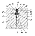
- the basic structure of the liquid-tight industrial floor covering consists of rectangular, in particular square, concrete floor slabs 1. These concrete floor slabs 1 are laid on a fine planum. They are kept at a distance from one another with the aid of intermediate spacers 2, forming joints 3. Above the spacers 2, the base plates 1 have on their end faces 4 a longitudinal chamber 5 arranged at a distance from the plate top 9. A joint seal 6 is introduced into the joints 3 formed between the concrete floor slabs 1, which has an expandable sealing strip 7 running in the longitudinal cavities 5 of adjacent concrete floor slabs 1.
- the joint seal 6 is constructed from two seal carriers 7, 8 in the form of a highly elastic joint grout, which are arranged one above the other.
- One sealing strand 7 is arranged exclusively in the longitudinal cavities 5 assigned to one another, while the other sealing strand 8 runs as it were adjacent to the top side 9 of the plate above the longitudinal cavities 5.
- This grouting of the two sealing strands 7 and 8 consists of a sealing material based on thiokol or polysulfide elastomer.
- the joint flanks 10 are provided, at least in the area of the two sealing strands 7, 8, with a reaction primer 11 based on epoxy resin, which is only indicated in the figure.
- the sealing strand 7 running in the longitudinal cavities 5 has a height which is smaller than the height of these longitudinal cavities 5.
- the said sealing string 7 ends in front of a sloping roof 12 of the longitudinal cavities 5.
- the latter have a chamber bottom 13 parallel to the top side 9 of the plate, on which a separating layer support 14 made of a chemical-resistant plastic film and extending over the entire joint width is arranged.
- the spacing 15 formed between the two sealing strands 7, 8 is filled with a filler made of foam rubber or polystyrene foam plastic.
- the two sealing strands 7 and 8 of high ductility are only connected to the corresponding surfaces 10 of the concrete slabs 1 on the vertical outer surfaces. In this way, the greatest possible working dimension for expansions is guaranteed with the smallest possible width.
Landscapes
- Engineering & Computer Science (AREA)
- Architecture (AREA)
- Civil Engineering (AREA)
- Structural Engineering (AREA)
- Building Environments (AREA)
- Floor Finish (AREA)
Abstract
Description
- Die Erfindung betrifft einen flüssigkeitsdichten Industriefußbodenbelag, bestehend aus Beton-Bodenplatten, die mit Hilfe von zwischengeschalteten Abstandshaltern unter Bildung von Fugen auf Abstand voneinander gehalten sind und oberhalb der Abstandshalter an ihren Stirnflächen eine mit Abstand von der Plattenoberseite angeordnete Längsauskammerung aufweisen, und aus einer in die Fugen eingebrachten Fugendichtung mit einem in den Längsauskammerungen benachbarter Bodenplatten verlaufenden dehnbaren Dichtungsstrang.
- Bei einem bekannten Industriefußbodenbelag der genannten Art (DE-U 89 03 419) besteht die Fugendichtung bzw. der Dichtungsstrang aus einem Gummi- oder Kunststoffprofil, das mit widerhakenartigen Vorkragflanschen in die Längsauskammerungen einfaßt. Das ist insgesamt zwar verhältnismäßig einfach und wenig aufwendig, bezüglich der Flüssigkeitsdichtigkeit jedoch ein wenig problematisch, weil bei fugenvergrößernden Belagbeanspruchungen die Flüssigkeitsdichtheit im Fugenbereich nicht immer gewährleistet ist, so daß dieser bekannte Industriefußbodenbelag überall dort, wo mit Flüssigkeiten manipuliert wird, die nicht in das Grundwasser gelangen dürfen, nicht einsetzbar ist.
- Aus der Praxis ist es zwar auch bekannt, die zwischen Beton-Bodenplatten gebildeten Fugen mit einem hochdehnbaren Fugenverguß auszufüllen. Auch das ist aber so ohne weiteres für den gegebenen Einsatzzweck ungeeignet. Die Fugen dürfen nämlich an der Oberfläche eine nicht zu große Breite besitzen, wenn anders eine Zerstörung der Fugendichtung durch Fahrzeuge u. dgl. nicht ausgeschlossen werden. Bei verhältnismäßig geringer Breite vermag ein solcher Fugenverguß ebenfalls nicht unter allen Beanspruchungen, die aus einer Relativbewegung der Betonplatten resultieren, Flüssigkeitsdichtheit zu gewährleisten.
- Der Erfindung liegt die Aufgabe zugrunde, einen Industriefußbodenbelag der eingangs genannten Art so weiter auszugestalten, daß Flüssigkeitsdichtheit in einem weit größeren Umfange als bisher gewährleistet ist.
- Hierzu lehrt die vorliegende Erfindung, daß die Fugendichtung aus zwei mit Abstand übereinander angeordneten Dichtungssträngen in Form eines hochdehnbaren Fugenvergusses besteht, von denen der eine ausschließlich in den einander zugeordneten Auskammerungen und der andere oberhalb derselben verläuft.
- Die Erfindung geht hierbei von der Erkenntnis aus, daß das eingangs geschilderte Problem des Fugenvergusses gemeistert werden kann, indem man eine Doppeldichtung aus zwei übereinandergeordneten Dichtungen verwirklicht, von denen die obere die von der Plattenoberseite herkommenden Beanspruchungen berücksichtigt, während man der unteren eine vergrößerte Breite gibt, die wesentlich größere Querbeanspruchungen aufzunehmen vermag und deshalb die Flüssigkeitsdichtheit auch dann noch gewährleistet, wenn diese durch die obere Dichtung nicht mehr gegeben ist.
- Für die weitere Ausgestaltung bestehen im Rahmen der Erdung mehrere Möglichkeiten. So hat sich in der Praxis eine Ausführungsform bewährt, bei der der Fugenverguß der beiden Dichtungsstränge aus einem Dichtungsmaterial auf Polysulfidelastomerbasis (Thiokol) besteht. Zur Erhöhung der Flüssigkeitsdichtheit empfiehlt es sich, die Fugenflanken zumindest im Bereich der beiden Dichtungsstränge mit einer Reaktionsgrundierung, insbes. auf Epoxidharzbasis, zu versehen; die Reaktionsgrundierung sorgt nämlich für einen verbesserten Anschluß der Dichtungsstränge an das Material der Beton-Bodenplatten. Um den unteren Dichtungsstrang bei vorgegebener Breite möglichst effektiv zu gestalten, sollte das Fugenvergußmaterial praktisch nur mit den vertikalen Flächen der Längsauskammerungen verbunden sein. Hierzu empfiehlt es sich, daß der in den Längsauskammerungen verlaufende Dichtungsstrang eine Höhe aufweist, die kleiner ist als die Höhe der Auskammerungen. Insbes. sollte der in den Längsauskammerungen verlaufende Dichtungsstrang vor einer aus betonherstellungstechnischen Gründen vorgesehenen Dachschräge der Längsauskammerungen enden. In die gleiche Richtung zielt auch die Maßnahme, den Längsauskammerungen einen zur Plattenoberseite parallelen Auskammerungsboden zu geben, auf dem eine sich über die gesamte Fugenbreite erstreckende Trennschichtauflage insbesondere aus einer chemikalienbeständigen Kunststoffolie angeordnet ist. Der zwischen den beiden Dichtungssträngen gebildete Abstandszwischenraum wird zweckmäßigerweise mit einem Füllstoff verfüllt; Schaumgummi oder Schaumkunststoff, insbesondere Polystyrol, sind hierfür besonders geeignet.
- Im folgenden wird die Erfindung anhand einer ein Ausführungsbeispiel darstellenden Zeichnung näher erläutert, deren einzige Figur in schematischer Darstellung einen Querschnitt durch einen Industriefußbodenbelag zeigt.
- Der flüssigkeitsdichte Industriefußbodenbelag besteht in seinem grundsätzlichen Aufbau aus rechteckigen, insbesondere quadratischen Beton-Bodenplatten 1. Diese Beton-Bodenplatten 1 sind auf einem Feinplanum verlegt. Sie sind mit Hilfe von zwischengeschalteten Abstandshaltern 2 unter Bildung von Fugen 3 auf Abstand voneinander gehalten. Oberhalb der Abstandshalter 2 weisen die Bodenplatten 1 an ihren Stirnflächen 4 eine mit Abstand von der Plattenoberseite 9 angeordnete Längsauskammerung 5 auf. In die zwischen den Beton-Bodenplatten 1 gebildeten Fugen 3 ist eine Fugendichtung 6 eingebracht, die einen in den Längsauskammerungen 5 benachbarter Beton-Bodenplatten 1 verlaufenden dehnbaren Dichtungsstrang 7 aufweist.
- Wie man aus der Figur unschwer erkennt, ist die Fugendichtung 6 aus zwei Dichtungsträgern 7, 8 in Form eines hochdehnbaren Fugenvergusses aufgebaut, die übereinander angeordnet sind. Der eine Dichtungsstrang 7 ist ausschließlich in den einander zugeordneten Längsauskammerungen 5 angeordnet, während der andere Dichtungsstrang 8 gleichsam an die Plattenoberseite 9 angrenzend oberhalb der Längsauskammerungen 5 verläuft. Dieser Fugenverguß der beiden Dichtungsstränge 7 und 8 besteht aus einem Dichtungsmaterial auf Thiokol- bzw. Polysulfidelastomerbasis.
- Die Fugenflanken 10 sind zumindest im Bereich der beiden Dichtungsstränge 7,8 mit einer Reaktionsgrundierung 11 auf Epoxidharzbasis versehen, was in der Figur nur angedeutet ist. Jedenfalls weist der in den Längsauskammerungen 5 verlaufende Dichtungsstrang 7 eine Höhe auf, die kleiner ist als die Höhe dieser Längsauskammerungen 5. Der genannte Dichtungsstrang 7 endet vor einer Dachschräge 12 der Längsauskammerungen 5. Letztere weisen einen zur Plattenoberseite 9 parallelen Auskammerungsboden 13 auf, auf dem eine sich über die gesamte Fugenbreite erstreckende Trennschichtauflage 14 aus einer chemikalienbeständigen Kunststoffolie angeordnet ist. Der zwischen den beiden Dichtungssträngen 7,8 gebildete Abstandszwischenraum 15 ist mit einem Füllstoff aus Schaumgummi oder Polystyrolschaumkunststoff verfüllt.
- Die beiden Dichtungsstränge 7 und 8 hoher Dehnbarkeit sind nur an den vertikalen Außenflächen mit den entsprechenden Flächen 10 der Betonplatten 1 in Verbund. Auf diese Weise ist bei geringstmöglicher Breite ein größtmögliches Arbeitsmaß bei Dehnungen gewährleistet.
Claims (10)
- Flüssigkeitsdichter Industriefußbodenbelag, bestehend aus Beton-Bodenplatten (1), die mit Hilfe von zwischengeschalteten Abstandshaltern (2) unter Bildung von Fugen (3) auf Abstand voneinander gehalten sind und oberhalb der Abstandshalter (2) an ihren Stirnflächen (4) ein mit Abstand von der Plattenoberseite angeordnete Längsauskammerung (5) aufweisen, und aus einer in die Fugen (3) eingebrachten Fugendichtung (6) mit einem in den Längsauskammerungen (5) benachbarter Bodenplatten (1) verlaufenden dehnbaren Dichtungsstrang (7), dadurch gekennzeichnet, daß die Fugendichtung (6) aus zwei mit Abstand übereinander angeordneten Dichtungssträngen (7, 8) in Form eines hochdehnbaren Fugenvergusses besteht, von denen der eine (7) ausschließlich in den einander zugeordneten Längsauskammerungen (5) und der andere (8) oberhalb derselben (5) verläuft.
- Flüssigkeitsdichter Industriefußbodenbelag nach Anspruch 1, dadurch gekennzeichnet, daß der Fugenverguß der beiden Dichtungsstränge (7, 8) aus einem Dichtungsmaterial auf Polysulfidelastomer - bzw. Thiokolbasis besteht.
- Flüssigkeitsdichter Industriefußbodenbelag nach Anspruch 1 oder 2, dadurch gekennzeichnet, daß die Fugenflanken (10) zumindest im Bereich der beiden Dichtungsstränge (7, 8) mit einer Reaktionsgrundierung (11) versehen ist.
- Flüssigkeitsdichter Industriefußbodenbelag nach Anspruch 3, dadurch gekennzeichnet, daß die Reaktionsgrundierung (11) auf Expoxidharzbasis ausgeführt ist.
- Flüssigkeitsdichter Industriefußbodenbelag nach einem der Ansprüche 1 bis 4, dadurch gekennzeichnet, daß der in den Längsauskammerungen (5) verlaufende Dichtungsstrang (7) eine Höhe aufweist, die kleiner ist als die Höhe der Auskammerungen (5).
- Flüssigkeitsdichter Industriefußbodenbelag nach Anspruch 5, dadurch gekennzeichnet, daß der in den Längsauskammerungen (5) verlaufende Dichtungsstrang (7) vor einer Dachschräge (12) der Längsauskammerungen (5) endet.
- Flüssigkeitsdichter Industriefußbodenbelag nach einem der Ansprüche 1 bis 6, dadurch gekennzeichnet, daß die Längsauskammerungen (5) einen zur Plattenoberseite (9) parallelen Auskammerungsboden (13) aufweisen, auf dem eine sich über die gesamte Fugenbreite erstreckende Trennschichtauflage (14) angeordnet ist.
- Flüssigkeitsdichter Industriefußbodenbelag nach Anspruch 7, dadurch gekennzeichnet, daß die Trennschichtauflage (14) aus einer chemikalienbeständigen Kunststoffolie besteht.
- Flüssigkeitsdichter Industriefußbodenbelag nach Anspruch 1 bis 8, dadurch gekennzeichnet, daß der zwischen den beiden Dichtungssträngen (7, 8) gebildete Abstandszwischenraum (15) mit einem Füllstoff verfüllt ist.
- Flüssigkeitsdichter Fußbodenbelag nach Anspruch 9, dadurch gekennzeichnet, daß der Füllstoff aus Schaumgummi oder Schaumkunststoff, insbesondere Polystyrol, besteht.
Priority Applications (3)
| Application Number | Priority Date | Filing Date | Title |
|---|---|---|---|
| DE9090104560T DE59000487D1 (de) | 1990-03-09 | 1990-03-09 | Fluessigkeitsdichter industriefussbodenbelag. |
| EP90104560A EP0445341B1 (de) | 1990-03-09 | 1990-03-09 | Flüssigkeitsdichter Industriefussbodenbelag |
| AT90104560T ATE82609T1 (de) | 1990-03-09 | 1990-03-09 | Fluessigkeitsdichter industriefussbodenbelag. |
Applications Claiming Priority (1)
| Application Number | Priority Date | Filing Date | Title |
|---|---|---|---|
| EP90104560A EP0445341B1 (de) | 1990-03-09 | 1990-03-09 | Flüssigkeitsdichter Industriefussbodenbelag |
Publications (2)
| Publication Number | Publication Date |
|---|---|
| EP0445341A1 true EP0445341A1 (de) | 1991-09-11 |
| EP0445341B1 EP0445341B1 (de) | 1992-11-19 |
Family
ID=8203740
Family Applications (1)
| Application Number | Title | Priority Date | Filing Date |
|---|---|---|---|
| EP90104560A Expired - Lifetime EP0445341B1 (de) | 1990-03-09 | 1990-03-09 | Flüssigkeitsdichter Industriefussbodenbelag |
Country Status (3)
| Country | Link |
|---|---|
| EP (1) | EP0445341B1 (de) |
| AT (1) | ATE82609T1 (de) |
| DE (1) | DE59000487D1 (de) |
Cited By (7)
| Publication number | Priority date | Publication date | Assignee | Title |
|---|---|---|---|---|
| WO1998055701A1 (de) * | 1997-06-07 | 1998-12-10 | Karl Kortmann | Auffangwanne |
| DE29814695U1 (de) * | 1998-08-17 | 1999-12-30 | Betonwerk Kwade GmbH & Co. KG, 48465 Schüttorf | Betonelement |
| WO2000011268A1 (de) * | 1998-08-17 | 2000-03-02 | Karl Kortmann | Betonelement mit haftverstärker-vorauftrag |
| WO2005098164A1 (en) * | 2004-04-06 | 2005-10-20 | Plante Rejean | Flooring system and method of installing same |
| CN101346571B (zh) * | 2005-12-23 | 2011-06-08 | 空中客车德国有限公司 | 利用密封膏制造可释放密封的方法和执行该方法用的粘合带的使用方法 |
| EP3241953A1 (de) * | 2016-05-06 | 2017-11-08 | SK Wiegrink Beteiligungs GmbH | Fugenfüllungsprofil |
| CN107740380A (zh) * | 2017-09-18 | 2018-02-27 | 杭州国电大坝安全工程有限公司 | 混凝土变形接缝抗冲磨防渗结构及其施工方法 |
Citations (4)
| Publication number | Priority date | Publication date | Assignee | Title |
|---|---|---|---|---|
| US3124047A (en) * | 1964-03-10 | Joint seal | ||
| FR1572639A (de) * | 1968-06-17 | 1969-06-27 | ||
| DE2413340A1 (de) * | 1974-03-20 | 1975-10-30 | Juergen Jora | Verfahren zum auskleiden von zwischen koerperwandungen liegenden fugen |
| DE8808272U1 (de) * | 1988-06-28 | 1988-12-22 | Brandner, Elisabeth, 8475 Wernberg-Köblitz | Vorrichtung zum Herstellen von Arbeitsfugen |
-
1990
- 1990-03-09 AT AT90104560T patent/ATE82609T1/de not_active IP Right Cessation
- 1990-03-09 DE DE9090104560T patent/DE59000487D1/de not_active Expired - Lifetime
- 1990-03-09 EP EP90104560A patent/EP0445341B1/de not_active Expired - Lifetime
Patent Citations (4)
| Publication number | Priority date | Publication date | Assignee | Title |
|---|---|---|---|---|
| US3124047A (en) * | 1964-03-10 | Joint seal | ||
| FR1572639A (de) * | 1968-06-17 | 1969-06-27 | ||
| DE2413340A1 (de) * | 1974-03-20 | 1975-10-30 | Juergen Jora | Verfahren zum auskleiden von zwischen koerperwandungen liegenden fugen |
| DE8808272U1 (de) * | 1988-06-28 | 1988-12-22 | Brandner, Elisabeth, 8475 Wernberg-Köblitz | Vorrichtung zum Herstellen von Arbeitsfugen |
Cited By (11)
| Publication number | Priority date | Publication date | Assignee | Title |
|---|---|---|---|---|
| WO1998055701A1 (de) * | 1997-06-07 | 1998-12-10 | Karl Kortmann | Auffangwanne |
| DE29814695U1 (de) * | 1998-08-17 | 1999-12-30 | Betonwerk Kwade GmbH & Co. KG, 48465 Schüttorf | Betonelement |
| WO2000011268A1 (de) * | 1998-08-17 | 2000-03-02 | Karl Kortmann | Betonelement mit haftverstärker-vorauftrag |
| WO2005098164A1 (en) * | 2004-04-06 | 2005-10-20 | Plante Rejean | Flooring system and method of installing same |
| CN101346571B (zh) * | 2005-12-23 | 2011-06-08 | 空中客车德国有限公司 | 利用密封膏制造可释放密封的方法和执行该方法用的粘合带的使用方法 |
| EP3241953A1 (de) * | 2016-05-06 | 2017-11-08 | SK Wiegrink Beteiligungs GmbH | Fugenfüllungsprofil |
| EP3412842A1 (de) | 2016-05-06 | 2018-12-12 | SK Wiegrink Beteiligungs GmbH | Fugenfüllungsprofil |
| EP3460135A1 (de) | 2016-05-06 | 2019-03-27 | SK Wiegrink Beteiligungs GmbH | Fugenfüllungsprofil |
| US10577806B2 (en) | 2016-05-06 | 2020-03-03 | Sk Wiegrink Beteiligungs Gmbh | Joint filling profile |
| EP3757313A1 (de) | 2016-05-06 | 2020-12-30 | SK Wiegrink Beteiligungs GmbH | Fugenfüllungsprofil |
| CN107740380A (zh) * | 2017-09-18 | 2018-02-27 | 杭州国电大坝安全工程有限公司 | 混凝土变形接缝抗冲磨防渗结构及其施工方法 |
Also Published As
| Publication number | Publication date |
|---|---|
| DE59000487D1 (de) | 1992-12-24 |
| ATE82609T1 (de) | 1992-12-15 |
| EP0445341B1 (de) | 1992-11-19 |
Similar Documents
| Publication | Publication Date | Title |
|---|---|---|
| DE2746365C3 (de) | Vorhangwand | |
| EP0985073A1 (de) | Untergrundseitig anzuklebendes profil zum abschluss von verlegten keramikplatten oder dergleichen | |
| DE1634382C3 (de) | Schalungshülle zum Herstellen von Betonplatten im Grundbau | |
| EP0445341B1 (de) | Flüssigkeitsdichter Industriefussbodenbelag | |
| DE3815140A1 (de) | Fugenschalung fuer glasbauelemente, welche aus mehreren glaselementen, insbesondere glasbausteinen bestehen | |
| DE2835606C2 (de) | Explosionssicheres Gebäude | |
| WO1990008866A1 (de) | Bauelement zur erstellung von gebäuden, gebäudeteilen od. dgl. | |
| EP0298283B1 (de) | Abdichtungsbauwerk aus einer vertikalen Schlitzwand und einer darin angeordneten Dichtwand | |
| DE2407727A1 (de) | Rahmenkonstruktion fuer fertigbauteile zum errichten von hochbauten aller art | |
| DE4411122A1 (de) | Bauwerk, bestehend aus vorgefertigen Bauteilen | |
| DE2111730A1 (de) | Bauelement fuer Gebaeudewaende | |
| DE1484067C3 (de) | Wandtafel aus bewehrtem Mauerwerk | |
| DE2237708A1 (de) | Profilstreifen | |
| DE2931608A1 (de) | Fassadenwand | |
| DE9203275U1 (de) | Schalung | |
| DE1559383B2 (de) | Versetzbare trennwand | |
| DE3623178C2 (de) | ||
| DE3429860A1 (de) | Gummiprofil | |
| DE9206523U1 (de) | Großflächenplatte für eine Flachdacheindeckung, insbesondere ein Parkdach | |
| DE2444548A1 (de) | Vorrichtung fuer die grosstafelbauweise zum verschliessen der senkrechten fugen zwischen den kanten benachbarter wandelemente | |
| AT257114B (de) | Gebäudekonstruktion | |
| DE7405614U (de) | Rahmenkonstruktion für Fertigbauteile zum Errichten von Hochbauten aller Art | |
| DD224070A1 (de) | Raumgitterstuetzwand | |
| DE8014149U1 (de) | Bewegungsfugen-Dichtungsprofil | |
| DE9203278U1 (de) | Schalung |
Legal Events
| Date | Code | Title | Description |
|---|---|---|---|
| PUAI | Public reference made under article 153(3) epc to a published international application that has entered the european phase |
Free format text: ORIGINAL CODE: 0009012 |
|
| 17P | Request for examination filed |
Effective date: 19901129 |
|
| AK | Designated contracting states |
Kind code of ref document: A1 Designated state(s): AT BE CH DE FR LI LU NL |
|
| 17Q | First examination report despatched |
Effective date: 19920506 |
|
| GRAA | (expected) grant |
Free format text: ORIGINAL CODE: 0009210 |
|
| AK | Designated contracting states |
Kind code of ref document: B1 Designated state(s): AT BE CH DE FR LI LU NL |
|
| REF | Corresponds to: |
Ref document number: 82609 Country of ref document: AT Date of ref document: 19921215 Kind code of ref document: T |
|
| REF | Corresponds to: |
Ref document number: 59000487 Country of ref document: DE Date of ref document: 19921224 |
|
| ET | Fr: translation filed | ||
| PLBE | No opposition filed within time limit |
Free format text: ORIGINAL CODE: 0009261 |
|
| STAA | Information on the status of an ep patent application or granted ep patent |
Free format text: STATUS: NO OPPOSITION FILED WITHIN TIME LIMIT |
|
| 26N | No opposition filed | ||
| PGFP | Annual fee paid to national office [announced via postgrant information from national office to epo] |
Ref country code: FR Payment date: 19940121 Year of fee payment: 5 |
|
| PGFP | Annual fee paid to national office [announced via postgrant information from national office to epo] |
Ref country code: BE Payment date: 19940131 Year of fee payment: 5 |
|
| PGFP | Annual fee paid to national office [announced via postgrant information from national office to epo] |
Ref country code: LU Payment date: 19940228 Year of fee payment: 5 |
|
| EPTA | Lu: last paid annual fee | ||
| PG25 | Lapsed in a contracting state [announced via postgrant information from national office to epo] |
Ref country code: LU Free format text: LAPSE BECAUSE OF NON-PAYMENT OF DUE FEES Effective date: 19950309 |
|
| PGFP | Annual fee paid to national office [announced via postgrant information from national office to epo] |
Ref country code: CH Payment date: 19950322 Year of fee payment: 6 Ref country code: AT Payment date: 19950322 Year of fee payment: 6 |
|
| PG25 | Lapsed in a contracting state [announced via postgrant information from national office to epo] |
Ref country code: BE Effective date: 19950331 |
|
| PGFP | Annual fee paid to national office [announced via postgrant information from national office to epo] |
Ref country code: NL Payment date: 19950331 Year of fee payment: 6 |
|
| BERE | Be: lapsed |
Owner name: STELCON A.G. Effective date: 19950331 |
|
| PG25 | Lapsed in a contracting state [announced via postgrant information from national office to epo] |
Ref country code: FR Free format text: LAPSE BECAUSE OF NON-PAYMENT OF DUE FEES Effective date: 19951130 |
|
| PG25 | Lapsed in a contracting state [announced via postgrant information from national office to epo] |
Ref country code: AT Effective date: 19960309 |
|
| REG | Reference to a national code |
Ref country code: FR Ref legal event code: ST |
|
| PG25 | Lapsed in a contracting state [announced via postgrant information from national office to epo] |
Ref country code: LI Effective date: 19960331 Ref country code: CH Effective date: 19960331 |
|
| PG25 | Lapsed in a contracting state [announced via postgrant information from national office to epo] |
Ref country code: NL Effective date: 19961001 |
|
| REG | Reference to a national code |
Ref country code: CH Ref legal event code: PL |
|
| NLV4 | Nl: lapsed or anulled due to non-payment of the annual fee |
Effective date: 19961001 |
|
| PGFP | Annual fee paid to national office [announced via postgrant information from national office to epo] |
Ref country code: DE Payment date: 20040211 Year of fee payment: 15 |
|
| PG25 | Lapsed in a contracting state [announced via postgrant information from national office to epo] |
Ref country code: DE Free format text: LAPSE BECAUSE OF NON-PAYMENT OF DUE FEES Effective date: 20051001 |