EP0445373B1 - Poignée pour véhicules automobiles - Google Patents
Poignée pour véhicules automobiles Download PDFInfo
- Publication number
- EP0445373B1 EP0445373B1 EP90122460A EP90122460A EP0445373B1 EP 0445373 B1 EP0445373 B1 EP 0445373B1 EP 90122460 A EP90122460 A EP 90122460A EP 90122460 A EP90122460 A EP 90122460A EP 0445373 B1 EP0445373 B1 EP 0445373B1
- Authority
- EP
- European Patent Office
- Prior art keywords
- column
- motor vehicle
- vehicle according
- handle
- seat arrangement
- Prior art date
- Legal status (The legal status is an assumption and is not a legal conclusion. Google has not performed a legal analysis and makes no representation as to the accuracy of the status listed.)
- Expired - Lifetime
Links
Images


Classifications
-
- B—PERFORMING OPERATIONS; TRANSPORTING
- B60—VEHICLES IN GENERAL
- B60N—SEATS SPECIALLY ADAPTED FOR VEHICLES; VEHICLE PASSENGER ACCOMMODATION NOT OTHERWISE PROVIDED FOR
- B60N3/00—Arrangements or adaptations of other passenger fittings, not otherwise provided for
- B60N3/02—Arrangements or adaptations of other passenger fittings, not otherwise provided for of hand grips or straps
Definitions
- the invention relates to a motor vehicle, in particular a passenger car, with a rear seat system and an internal B-pillar, which is partially completely clad to the outside in sections by two visors placed one against the other.
- the B-pillar runs parallel from the belt line to the overhead lateral roof frame and at a distance from the outer viewing panels.
- a disadvantage of this arrangement is that no precautions have been taken on the B-pillar so that the occupants of the rear seat system can hold on if necessary.
- the object of the invention is to take such precautions on a B-pillar that the above-mentioned disadvantages are avoided.
- the main advantages achieved with the invention are that the construction of the B-pillar as a handle creates a simple and inexpensive structure for the occupants of the rear seat system. Subsequent installation and additional fasteners for the handle are not required.
- the handle is formed by an inwardly arcuate section of the B-pillar, the section running at a distance from the outer viewing panes.
- the handle is formed by a bracket-like molding on the B-pillar.
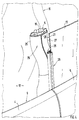
- the passenger car 1 shown in FIG. 1 has a body 2 in the area shown, which is composed of a roof 3, a front door 4 and a rear door 5. Extending between the two doors 4, 5 is an upright B-pillar 6, which is firmly connected on the one hand to a vehicle side member 7 (sill) located underneath and on the other hand to a side roof frame 8.
- Each door 4, 5 consists of a door body 10, 11, which extends approximately up to the level of a belt line 9, and a height-adjustable viewing window 12, 13, the two viewing windows 12, 13 above the belt line 9 being frameless.
- the two windows 12, 13 are - seen in the longitudinal direction of the vehicle - put together to form a joint 14 and completely cover the inner B-pillar (6).
- a passenger compartment 15 is accessible through the doors 4, 5, which has front seats 16 and a rear seat system 17 for vehicle occupants 18.
- the B-pillar 6, which is composed of two hat profiles 19, 20 and forms a box-shaped hollow beam, tapers continuously from bottom to top and is designed in some areas as a handle 21 for the vehicle occupants 18 of the rear seat system 17.
- the handle 21 is formed by a bow-like molding 22 of the B-pillar 6.
- the projection 22 is arranged on the side of the B-pillar 6 facing the rear seat system 17 and is aligned in the longitudinal direction of the vehicle. 1 is a crescent-shaped opening 23 between the B-pillar 6 and the molding 22 Passing through a hand 24 of an occupant 18 of the rear seat system 17 is provided.
- the molding 22 extends at a lateral distance A from the outer viewing pane 13.
- the molding 22 can either be formed in one piece with the B-pillar 6 or can be formed by a separate part which is firmly connected to the B-pillar.
- the B-pillar 6 and the molding 22 can be provided with a covering 25, which is formed, for example, by a covering made of energy-absorbing foam and / or a cover layer made of plastic or leather (FIG. 2).
- the handle 21 is formed by an inwardly arcuate section 26 of the B-pillar 6, such that a space locally between the outer lenses 12, 13 and the inwardly drawn B-pillar 6 27 for passing the hand 24 of a vehicle occupant 18 of the rear seat system 17 is present.
- the height H of the arcuate section 26 depends on the width of the back of the hand of the vehicle occupant 18.
- Both embodiments of the handle 21 are arranged approximately above or adjacent to the belt line 9.
- the rear window 13 is formed by a fixed rear side window of the passenger car 1, which covers the inner B-pillar 6 in sections.
- the sealing between the two adjacent viewing panes 12, 13 takes place by means of a sealing body 28 which is plugged onto the rear viewing pane 13 and which projects beyond the front viewing pane 12 and presses against the front viewing pane 12 from the inside with a tubular profile 29.
Landscapes
- Engineering & Computer Science (AREA)
- Transportation (AREA)
- Mechanical Engineering (AREA)
- Passenger Equipment (AREA)
- Body Structure For Vehicles (AREA)
Claims (8)
- Véhicule automobile, en particulier voiture de tourisme comportant un banquette arrière (17) et un montant B (6) intérieur, qui est revêtu de l'extérieur, par parties, par deux vitres (12, 13) opposées l'une à l'autre, vues dans la direction longitudinale du véhicule, caractérisé en ce que le montant B (6) est conçu dans une zone comme une poignée (21) pour les passagers (18) de la banquette arrière (17).
- Véhicule automobile selon la revendication 1, caractérisé en ce que la poignée (21) est constituée par un étrier (22) formé sur le montant B (6), qui est placé sur le côté tourné vers la banquette arrière (17) du montant B (6).
- Véhicule automobile selon la revendication 2, caractérisé en ce que l'étrier (22) s'étend dans la direction longitudinale du véhicule et fait saillie du montant B (6) en direction de la banquette arrière (17).
- Véhicule automobile selon la revendication 2, caractérisé en ce qu'il est prévu, entre le montant B (6) et l'étrier (22), une ouverture (23) en forme de croissant pour qu'un passager (18) de la banquette arrière (17) puisse passer la main (24).
- Véhicule automobile selon la revendication 2, caractérisé en ce que l'étrier (22) se trouve à une distance latérale (A) de la vitre (13) extérieure.
- Véhicule automobile selon la revendication 1, caractérisé en ce que le montant B (6) présente localement une partie (26) en forme d'arc dirigée vers l'intérieur - dans la direction transversale du véhicule - qui forme la poignée (21).
- Véhicule automobile selon la revendication 6, caractérisé en ce que la partie en arc (26) est suffisamment en retrait vers l'intérieur pour qu'un passager (18) de la banquette arrière (17) puisse passer la main (24) entre le montant B (6) et les vitres extérieures (12, 13).
- Véhicule automobile selon la revendication 1, caractérisé en ce que la poignée (21), formée sur le montant B (6), se situe au-dessus ou à proximité d'une ligne médiane (9).
Applications Claiming Priority (2)
| Application Number | Priority Date | Filing Date | Title |
|---|---|---|---|
| DE4005589A DE4005589A1 (de) | 1990-02-22 | 1990-02-22 | Kraftfahrzeug, insbesondere personenwagen |
| DE4005589 | 1990-02-22 |
Publications (2)
| Publication Number | Publication Date |
|---|---|
| EP0445373A1 EP0445373A1 (fr) | 1991-09-11 |
| EP0445373B1 true EP0445373B1 (fr) | 1993-06-02 |
Family
ID=6400734
Family Applications (1)
| Application Number | Title | Priority Date | Filing Date |
|---|---|---|---|
| EP90122460A Expired - Lifetime EP0445373B1 (fr) | 1990-02-22 | 1990-11-26 | Poignée pour véhicules automobiles |
Country Status (3)
| Country | Link |
|---|---|
| EP (1) | EP0445373B1 (fr) |
| JP (1) | JPH04215535A (fr) |
| DE (2) | DE4005589A1 (fr) |
Families Citing this family (3)
| Publication number | Priority date | Publication date | Assignee | Title |
|---|---|---|---|---|
| DE19503219A1 (de) * | 1995-02-02 | 1996-08-08 | Happich Gmbh Gebr | Dachrahmen |
| GB2367040B (en) * | 2000-09-25 | 2003-11-12 | Ford Global Tech Inc | A grab handle and seatbelt support ring and a method relating thereto |
| DE102007022330A1 (de) | 2007-05-12 | 2008-11-13 | GM Global Technology Operations, Inc., Detroit | Kraftfahrzeugsäule mit Haltegriff |
Family Cites Families (9)
| Publication number | Priority date | Publication date | Assignee | Title |
|---|---|---|---|---|
| GB191220420A (en) * | 1912-09-07 | 1913-02-13 | Philipp Strasser | Improvements in and connected with Motor Driven Vehicles. |
| DE883407C (de) * | 1949-10-28 | 1955-08-16 | Daimler Benz Ag | Griffstangenanordnung im Innern von Kraftfahrzeugen, insbesondere fuer Personenwagen |
| US2768590A (en) * | 1952-05-07 | 1956-10-30 | Arthur C Otto | Hand rail attachment for motor vehicles |
| GB806930A (en) * | 1956-05-02 | 1959-01-07 | Vauxhall Motors Ltd | Improvements in motor car body construction |
| US3182606A (en) * | 1963-05-14 | 1965-05-11 | Bradley D Osgood | Vehicle entry and exit assist strap and bracket |
| US4072339A (en) * | 1976-07-15 | 1978-02-07 | Rothlisberger Melvin Albert | High ground clearance passenger vehicle handle apparatus |
| DE2900056C3 (de) * | 1979-01-02 | 1981-11-12 | Waggonfabrik Uerdingen AG, Werk Düsseldorf, 4000 Düsseldorf | Anordnung zum Befestigen einer Haltestange, insbesondere bei Fahrzeugen zur Personenbeförderung |
| JPS60207997A (ja) * | 1984-03-31 | 1985-10-19 | 松下電工株式会社 | 超音波式二重防犯装置 |
| JPH02162898A (ja) * | 1988-12-15 | 1990-06-22 | Matsushita Electric Works Ltd | 超音波センサ |
-
1990
- 1990-02-22 DE DE4005589A patent/DE4005589A1/de not_active Withdrawn
- 1990-11-26 EP EP90122460A patent/EP0445373B1/fr not_active Expired - Lifetime
- 1990-11-26 DE DE9090122460T patent/DE59001620D1/de not_active Expired - Fee Related
-
1991
- 1991-02-20 JP JP3026165A patent/JPH04215535A/ja active Pending
Also Published As
| Publication number | Publication date |
|---|---|
| JPH04215535A (ja) | 1992-08-06 |
| EP0445373A1 (fr) | 1991-09-11 |
| DE4005589A1 (de) | 1991-08-29 |
| DE59001620D1 (de) | 1993-07-08 |
Similar Documents
| Publication | Publication Date | Title |
|---|---|---|
| DE2655990C2 (fr) | ||
| DE69301923T2 (de) | Querteil für ein armaturenbrett für ein kraftfahrzeug | |
| EP0960802B2 (fr) | Toit de véhicule | |
| DE3313658C2 (de) | Aufbau für Personen- oder Kombinationskraftwagen | |
| EP0811517B1 (fr) | Capote pliante pour véhicule, en particulier pour véhicule automobile | |
| EP0648629B1 (fr) | Carrosserie de véhicule | |
| EP1911662B1 (fr) | Fond de caisse d'un véhicule et système de plate-forme | |
| EP1036688A2 (fr) | Véhicule automobile en particulier véhicule de passagers | |
| DE3116094A1 (de) | "automobilfenster" | |
| DE29719025U1 (de) | Beleuchtungssystem für einen Personenkraftwagen | |
| DE3607855A1 (de) | Fahrgastzelle eines kraftfahrzeugs | |
| DE4342960C1 (de) | Fahrgastzelle für einen Personenkraftwagen mit einer tragenden Rohbaustruktur | |
| DE102005007107B4 (de) | Fahrzeug mit einer Karosseriestruktur, welche ein einen Fensterheber aufnehmendes Aufnahmefach enthält | |
| DE2929915A1 (de) | Dachanordnung fuer ein kraftfahrzeug | |
| WO2008052727A1 (fr) | Véhicule léger à construction ouverte | |
| DE3809196A1 (de) | Fahrzeugdach, insbesondere fuer personenkraftwagen | |
| DE2021906A1 (de) | Tuer fuer Fahrzeuge | |
| DE4440730C1 (de) | Dachkonstruktion für ein Kraftfahrzeug mit beweglichem Dachabschnitt | |
| EP0443110A1 (fr) | Agencement de ceinture de sécurité pour les sièges arrières d'un véhicule automobile | |
| DE3209933A1 (de) | Einrichtung zum einbau von scheiben, insbesondere seitenscheiben in tueren von kraftfahrzeugen | |
| EP0445373A1 (fr) | Poignée pour véhicules automobiles | |
| DE19751671B4 (de) | Trennwand für ein Kraftfahrzeug | |
| EP0865951B1 (fr) | Hardtop amovible pour un véhicule automobile | |
| DE4102944A1 (de) | Kraftfahrzeugkarosserie mit wenigstens einem, von einer tuer oder dergleichen abdeckbaren tuerausschnitt | |
| DE60003256T2 (de) | Verkleidungsanordnung für einen Kraftfahrzeugblechteil |
Legal Events
| Date | Code | Title | Description |
|---|---|---|---|
| PUAI | Public reference made under article 153(3) epc to a published international application that has entered the european phase |
Free format text: ORIGINAL CODE: 0009012 |
|
| AK | Designated contracting states |
Kind code of ref document: A1 Designated state(s): DE FR GB IT NL SE |
|
| 17P | Request for examination filed |
Effective date: 19920425 |
|
| 17Q | First examination report despatched |
Effective date: 19921102 |
|
| GRAA | (expected) grant |
Free format text: ORIGINAL CODE: 0009210 |
|
| AK | Designated contracting states |
Kind code of ref document: B1 Designated state(s): DE FR GB IT NL SE |
|
| ITF | It: translation for a ep patent filed | ||
| REF | Corresponds to: |
Ref document number: 59001620 Country of ref document: DE Date of ref document: 19930708 |
|
| ET | Fr: translation filed | ||
| GBT | Gb: translation of ep patent filed (gb section 77(6)(a)/1977) |
Effective date: 19930802 |
|
| PGFP | Annual fee paid to national office [announced via postgrant information from national office to epo] |
Ref country code: SE Payment date: 19931110 Year of fee payment: 4 |
|
| PGFP | Annual fee paid to national office [announced via postgrant information from national office to epo] |
Ref country code: NL Payment date: 19931130 Year of fee payment: 4 |
|
| PLBE | No opposition filed within time limit |
Free format text: ORIGINAL CODE: 0009261 |
|
| STAA | Information on the status of an ep patent application or granted ep patent |
Free format text: STATUS: NO OPPOSITION FILED WITHIN TIME LIMIT |
|
| 26N | No opposition filed | ||
| PG25 | Lapsed in a contracting state [announced via postgrant information from national office to epo] |
Ref country code: SE Effective date: 19941127 |
|
| EAL | Se: european patent in force in sweden |
Ref document number: 90122460.0 |
|
| PG25 | Lapsed in a contracting state [announced via postgrant information from national office to epo] |
Ref country code: NL Effective date: 19950601 |
|
| NLV4 | Nl: lapsed or anulled due to non-payment of the annual fee | ||
| EUG | Se: european patent has lapsed |
Ref document number: 90122460.0 |
|
| PGFP | Annual fee paid to national office [announced via postgrant information from national office to epo] |
Ref country code: FR Payment date: 19971031 Year of fee payment: 8 |
|
| PGFP | Annual fee paid to national office [announced via postgrant information from national office to epo] |
Ref country code: GB Payment date: 19971117 Year of fee payment: 8 |
|
| PG25 | Lapsed in a contracting state [announced via postgrant information from national office to epo] |
Ref country code: GB Free format text: LAPSE BECAUSE OF NON-PAYMENT OF DUE FEES Effective date: 19981126 |
|
| PGFP | Annual fee paid to national office [announced via postgrant information from national office to epo] |
Ref country code: DE Payment date: 19981127 Year of fee payment: 9 |
|
| GBPC | Gb: european patent ceased through non-payment of renewal fee |
Effective date: 19981126 |
|
| PG25 | Lapsed in a contracting state [announced via postgrant information from national office to epo] |
Ref country code: FR Free format text: LAPSE BECAUSE OF NON-PAYMENT OF DUE FEES Effective date: 19990730 |
|
| REG | Reference to a national code |
Ref country code: FR Ref legal event code: ST |
|
| PG25 | Lapsed in a contracting state [announced via postgrant information from national office to epo] |
Ref country code: DE Free format text: LAPSE BECAUSE OF NON-PAYMENT OF DUE FEES Effective date: 20000901 |
|
| PG25 | Lapsed in a contracting state [announced via postgrant information from national office to epo] |
Ref country code: IT Free format text: LAPSE BECAUSE OF NON-PAYMENT OF DUE FEES;WARNING: LAPSES OF ITALIAN PATENTS WITH EFFECTIVE DATE BEFORE 2007 MAY HAVE OCCURRED AT ANY TIME BEFORE 2007. THE CORRECT EFFECTIVE DATE MAY BE DIFFERENT FROM THE ONE RECORDED. Effective date: 20051126 |