EP0445407A1 - Antriebs-Aggregat, insbesondere zum Antrieb eines Fahrzeuges - Google Patents
Antriebs-Aggregat, insbesondere zum Antrieb eines Fahrzeuges Download PDFInfo
- Publication number
- EP0445407A1 EP0445407A1 EP90124706A EP90124706A EP0445407A1 EP 0445407 A1 EP0445407 A1 EP 0445407A1 EP 90124706 A EP90124706 A EP 90124706A EP 90124706 A EP90124706 A EP 90124706A EP 0445407 A1 EP0445407 A1 EP 0445407A1
- Authority
- EP
- European Patent Office
- Prior art keywords
- engine
- motor
- auxiliary
- unit according
- star
- Prior art date
- Legal status (The legal status is an assumption and is not a legal conclusion. Google has not performed a legal analysis and makes no representation as to the accuracy of the status listed.)
- Granted
Links
- 238000002485 combustion reaction Methods 0.000 claims abstract description 3
- 230000008878 coupling Effects 0.000 claims description 2
- 238000010168 coupling process Methods 0.000 claims description 2
- 238000005859 coupling reaction Methods 0.000 claims description 2
- 230000000712 assembly Effects 0.000 abstract description 2
- 238000000429 assembly Methods 0.000 abstract description 2
- 238000009434 installation Methods 0.000 description 4
- 238000004378 air conditioning Methods 0.000 description 2
- 230000005540 biological transmission Effects 0.000 description 1
- 238000005253 cladding Methods 0.000 description 1
- 239000002826 coolant Substances 0.000 description 1
Images
Classifications
-
- F—MECHANICAL ENGINEERING; LIGHTING; HEATING; WEAPONS; BLASTING
- F02—COMBUSTION ENGINES; HOT-GAS OR COMBUSTION-PRODUCT ENGINE PLANTS
- F02B—INTERNAL-COMBUSTION PISTON ENGINES; COMBUSTION ENGINES IN GENERAL
- F02B67/00—Engines characterised by the arrangement of auxiliary apparatus not being otherwise provided for, e.g. the apparatus having different functions; Driving auxiliary apparatus from engines, not otherwise provided for
-
- F—MECHANICAL ENGINEERING; LIGHTING; HEATING; WEAPONS; BLASTING
- F02—COMBUSTION ENGINES; HOT-GAS OR COMBUSTION-PRODUCT ENGINE PLANTS
- F02B—INTERNAL-COMBUSTION PISTON ENGINES; COMBUSTION ENGINES IN GENERAL
- F02B73/00—Combinations of two or more engines, not otherwise provided for
-
- F—MECHANICAL ENGINEERING; LIGHTING; HEATING; WEAPONS; BLASTING
- F02—COMBUSTION ENGINES; HOT-GAS OR COMBUSTION-PRODUCT ENGINE PLANTS
- F02B—INTERNAL-COMBUSTION PISTON ENGINES; COMBUSTION ENGINES IN GENERAL
- F02B75/00—Other engines
- F02B75/16—Engines characterised by number of cylinders, e.g. single-cylinder engines
- F02B75/18—Multi-cylinder engines
- F02B75/22—Multi-cylinder engines with cylinders in V, fan, or star arrangement
-
- F—MECHANICAL ENGINEERING; LIGHTING; HEATING; WEAPONS; BLASTING
- F02—COMBUSTION ENGINES; HOT-GAS OR COMBUSTION-PRODUCT ENGINE PLANTS
- F02B—INTERNAL-COMBUSTION PISTON ENGINES; COMBUSTION ENGINES IN GENERAL
- F02B75/00—Other engines
- F02B75/02—Engines characterised by their cycles, e.g. six-stroke
- F02B2075/022—Engines characterised by their cycles, e.g. six-stroke having less than six strokes per cycle
- F02B2075/025—Engines characterised by their cycles, e.g. six-stroke having less than six strokes per cycle two
-
- F—MECHANICAL ENGINEERING; LIGHTING; HEATING; WEAPONS; BLASTING
- F02—COMBUSTION ENGINES; HOT-GAS OR COMBUSTION-PRODUCT ENGINE PLANTS
- F02B—INTERNAL-COMBUSTION PISTON ENGINES; COMBUSTION ENGINES IN GENERAL
- F02B75/00—Other engines
- F02B75/16—Engines characterised by number of cylinders, e.g. single-cylinder engines
- F02B75/18—Multi-cylinder engines
- F02B2075/1804—Number of cylinders
- F02B2075/1816—Number of cylinders four
-
- Y—GENERAL TAGGING OF NEW TECHNOLOGICAL DEVELOPMENTS; GENERAL TAGGING OF CROSS-SECTIONAL TECHNOLOGIES SPANNING OVER SEVERAL SECTIONS OF THE IPC; TECHNICAL SUBJECTS COVERED BY FORMER USPC CROSS-REFERENCE ART COLLECTIONS [XRACs] AND DIGESTS
- Y10—TECHNICAL SUBJECTS COVERED BY FORMER USPC
- Y10S—TECHNICAL SUBJECTS COVERED BY FORMER USPC CROSS-REFERENCE ART COLLECTIONS [XRACs] AND DIGESTS
- Y10S123/00—Internal-combustion engines
- Y10S123/08—Multiple engine units
Definitions
- the invention relates to a drive unit, in particular for driving a vehicle, according to the preamble of claim 1.
- a drive unit with a traction motor is known, to which an auxiliary motor for optionally driving auxiliary units is assigned.
- the auxiliary motor which is used to drive the auxiliary units if necessary, is arranged on the side of the traction motor.
- the auxiliary units are arranged at a distance from the free end areas of both motors and are essentially structurally assigned to the auxiliary motor.
- the disadvantage here is the considerable installation space.
- the invention has for its object to show an arrangement of an auxiliary motor with less need for installation space for a generic drive unit.
- a single-star motor designed as an internal combustion engine is arranged as an auxiliary motor in a free end region of the traction motor.
- a particularly advantageous space-saving arrangement is achieved with a single-star engine, which is designed as a 4-cylinder 2-stroke engine with a crank loop engine.
- this single-star motor which is described in more detail, for example, in EP-A-0 187 930, a short, compact and powerful auxiliary motor is achieved for a space-saving arrangement.
- the invention is advantageous not only in terms of the size of the auxiliary motor. It is also of considerable advantage with regard to the overall arrangement in that auxiliary units provided in the front end region of the traction motor can be used, provided that installation space can be used, thus eliminating the need for a separate arrangement requiring additional installation space.
- the coupling be in rotary connection on the outside with driven disks of enveloping gears provided in several planes in the free end region of the drive motor for driving the auxiliary units.
- the above-described switchable clutch can be designed so that the auxiliary units can be driven by the single-star engine when the vehicle is at a standstill, idling or possibly under a heavy load on the drive motor. According to claim 5, however, an operating mode is also conceivable for the switchable clutch such that, if necessary, only a part of the auxiliary units is driven by the single-star motor. This especially for the case that one or more of these separately selectively driven auxiliary units have to deliver an increased power that cannot be achieved while maintaining the given speed of the traction motor, such as, for example, increased air conditioning power and / or increased electrical consumption from the vehicle electrical system at low driving speed or a stop -and-go driving style of the vehicle.
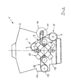
- An assembly 1 serving to drive a vehicle comprises a traction motor 2 serving to drive the vehicle, with numerous auxiliary assemblies arranged in the end region.
- Auxiliary units are provided with a coolant pump 3 with a drive pulley 4 and a power steering pump 5 with a drive pulley 6.
- the drive pulleys 4 and 6 lie with a driven pulley 8 assigned to the engine shaft 7 of the traction motor 2 in one plane of an enveloping transmission 9.
- Additional auxiliary units are a generator 10 with a drive pulley 11 and an air conditioning compressor 12 with a drive pulley 13.
- the drive pulleys 11 and 13 are located with a further, the output disk 14 assigned to the engine shaft 7 in another plane of a second sheathing gear 15.
- an auxiliary motor 17 is arranged in alignment, which serves to selectively drive the aforementioned auxiliary units 3, 5, 10, 12.
- the auxiliary motor 17 arranged in the free end region of the drive motor 2 is designed as a single-star motor 18.
- the single-star motor 18 is designed as a 4-cylinder, 2-stroke engine with a crank-loop engine (EP-A-0 187 930).
- the switchable clutch 16 is connected on the outside in a rotationally fixed connection to the driven disks 8 and 14 of the cladding gears 9 and 15 of the auxiliary units 3, 5 and 10, 12 divided into two groups.
- the clutch 16 is switchable in such a way that either both groups of auxiliary units 3, 5 and 10, 12 or, depending on requirements, one of groups 3, 5 and 10, 12 can be operated via the single-star motor 18.
- the single-star motor 18 arranged on the traction motor 2 can also be designed with the switchable clutch 16 as a retrofit kit.
Landscapes
- Engineering & Computer Science (AREA)
- Chemical & Material Sciences (AREA)
- Combustion & Propulsion (AREA)
- Mechanical Engineering (AREA)
- General Engineering & Computer Science (AREA)
- Hybrid Electric Vehicles (AREA)
- Management, Administration, Business Operations System, And Electronic Commerce (AREA)
- Auxiliary Drives, Propulsion Controls, And Safety Devices (AREA)
- Arrangement Of Transmissions (AREA)
- Arrangement Or Mounting Of Propulsion Units For Vehicles (AREA)
Abstract
Description
- Die Erfindung bezieht sich auf ein Antriebs-Aggregat, insbesondere zum Antrieb eines Fahrzeuges, nach dem Oberbegriff des Patentanspruches 1.
- Aus der FR-A-1 463 799 ist ein Antriebs-Aggregat mit einem Fahrmotor bekannt, dem ein Hilfsmotor zum wahlweisen Antrieb von Hilfsaggregaten zugeordnet ist. Der im Bedarfsfall zum Antrieb der Hilfsaggregate dienende Hilfsmotor ist seitlich des Fahrmotors angeordnet. Die Hilfsaggregate sind von den freien Stirnbereichen beider Motore beabstandet angeordnet und baulich im wesentlichen dem Hilfsmotor zugeordnet. Nachteilig hierbei ist der erhebliche Einbauraum.
- Der Erfindung liegt die Aufgabe zugrunde, für ein gattungsgemäßes Antriebs-Aggregat eine Anordnung eines Hilfsmotors mit geringerem Bedarf an Einbauraum aufzuzeigen.
- Diese Aufgabe wird gemäß dem Kennzeichen des Patentanspruches 1 dadurch gelöst, daß in einem freien Stirnbereich des Fahrmotors als Hilfsmotor ein als Brennkraftmaschine ausgebildeter Einsternmotor angeordnet ist. Eine besonders vorteilhaft platzsparende Anordnung ist nach Anspruch 2 mit einem Einsternmotor erreicht, der als 4-Zylinder-2-Takt-Motor mit einem Kurbelschlaufen-Triebwerk ausgebildet ist. Mit diesem beispielsweise in der EP-A-0 187 930 näher beschriebenen Einsternmotor ist für eine platzsparende Anordnung ein kurzbauender, kompakter und leistungsstarker Hilfsmotor erzielt. Die Erfindung ist jedoch nicht nur hinsichtlich der Baugröße des Hilfsmotors von Vorteil. Sie ist auch hinsichtlich der Gesamt-Anordnung von erheblichem Vorteil dadurch, daß im stirnseitigen Endbereich des Fahrmotors vorgesehene, gegebenen Einbauraum nutzend angeordnete Hilfsaggregate verbleiben können und damit eine gesonderte, zusätzlichen Einbauraum erfordernde Anordnung entfällt.
- Diese vorteilhafte Anordnung wird in einfacher Weise nach Anspruch 3 zusätzlich dadurch unterstützt, daß der Einsternmotor unter Zwischenschaltung einer schaltbaren Kupplung fluchtend mit einer Triebwerkswelle des Fahrmotors angeordnet ist.
- In weiterer Ausgestaltung der erfindungsgemäßen Anordnung wird zur Erzielung einer kurzen Gesamtlänge des Antriebs-Aggregates nach Anspruch 4 vorgeschlagen, daß die Kupplung außenumfänglich in Drehverbindung steht mit Abtriebsscheiben von in mehreren Ebenen im freien Stirnbereich des Fahrmotors vorgesehenen Hüllgetrieben zum Antrieb der Hilfsaggregate.
- Die vorbeschriebene schaltbare Kupplung kann so gestaltet sein, daß über diese wahlweise die Hilfsaggregate durch den Einsternmotor bei Stillstand, Leerlauf oder evtl. bei starker Belastung des Fahrmotors angetrieben sind. Nach Anspruch 5 ist für die schaltbare Kupplung jedoch auch eine Betriebsweise denkbar derart, daß bei Bedarf lediglich ein Teil der Hilfsaggregate von dem Einsternmotor angetrieben wird. Dies insbesondere für den Fall, daß ein oder mehrere dieser gesondert wahlweise angetriebenen Hilfsaggregate eine erhöhte Leistung abzugeben haben, die bei Beibehaltung der gegebenen Drehzahl des Fahrmotors nicht zu erbringen ist, wie beispielsweise verstärkte Klimaleistung und/oder erhöhter elektrischer Verbrauch aus dem Bordnetz bei geringer Fahrgeschwindigkeit oder einer Stop-and-Go-Fahrweise des Fahrzeuges.
- Nach Anspruch 6 wird schließlich vorgeschlagen, daß Einsternmotor und schaltbare Kupplung einen Nachrüstsatz bilden.
- Die Erfindung ist anhand eines schematisch dargestellten Ausführungsbeispiels beschrieben. Es zeigt:
- Fig. 1
- ein Antriebs-Aggregat in Stirnansicht,
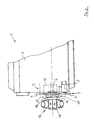
- Fig. 2
- das Antriebs-Aggregat nach Fig. 1 teilweise in Seitenansicht.
- Ein zum Antrieb eines nicht dargestellten Fahrzeuges dienendes Aggregat 1 umfaßt einen zum Fahrzeug-Antrieb dienenden Fahrmotor 2 mit zahlreichen, im stirnseitigen Endbereich angeordneten Hilfsaggregaten. An Hilfsaggregaten sind vorgesehen eine Kühlmittelpumpe 3 mit einer Antriebsscheibe 4 und eine Lenkhilfepumpe 5 mit einer Antriebsscheibe 6. Die Antriebsscheiben 4 und 6 liegen mit einer der Triebwerkswelle 7 des Fahrmotors 2 zugeordneten Abtriebsscheibe 8 in einer Ebene eines Hüllgetriebes 9. Weitere Hilfsaggregate sind ein Generator 10 mit einer Antriebsscheibe 11 und ein Klimakompressor 12 mit einer Antriebsscheibe 13. Die Antriebsscheiben 11 und 13 liegen mit einer weiteren, der Triebwerkswelle 7 zugeordneten Abtriebsscheibe 14 in einer anderen Ebene eines zweiten Hüllgetriebes 15.
- Mit der Triebwerkswelle 7 des Fahrmotors 2 ist unter Zwischenschaltung einer schaltbaren Kupplung 16 fluchtend ein Hilfsmotor 17 angeordnet, der dem wahlweisen Antrieb der vorgenannten Hilfsaggregate 3, 5, 10, 12 dient.
- Zur Erzielung einer kurzen Gesamt-Baulänge des Antriebs-Aggregates 1 ist der im freien Stirnbereich des Fahrmotors 2 angeordnete Hilfsmotor 17 als Einsternmotor 18 gestaltet. Um mit platzsparender Anordnung einen kurzbauenden, kompakten und leistungsstarken Hilfsmotor 17 zu erreichen, ist der Einsternmotor 18 als ein 4-Zylinder-2-Takt-Motor mit Kurbelschlaufen-Triebwerk (EP-A-0 187 930) ausgeführt.
- Zum wahlweisen Antrieb der vorgenannten Hilfsaggregate 3, 5, 10, 12 steht die schaltbare Kupplung 16 außenumfänglich in drehfester Verbindung mit den Abtriebsscheiben 8 und 14 der Hüllgetriebe 9 und 15 der in zwei Gruppen aufgeteilten Hilfsaggregate 3, 5 und 10, 12. Die Kupplung 16 ist in der Weise schaltbar, daß entweder beide Gruppen der Hilfsaggregate 3, 5 und 10, 12 oder aber je nach Bedarf eine der Gruppen 3, 5 bzw. 10, 12 über den Einsternmotor 18 betreibbar ist.
- Der am Fahrmotor 2 angeordnete Einsternmotor 18 kann mit der schaltbaren Kupplung 16 auch als Nachrüstsatz ausgebildet sein.
Claims (6)
- Antriebs-Aggregat, insbesondere zum Antrieb eines Fahrzeuges,- umfassend einen Fahrmotor (2) und einen Hilfsmotor (17) sowie Hilfsaggregate (3,5,10,12), die- wahlweise von einem der Motore antreibbar sind, dadurch gekennzeichnet,- daß in einem freien Stirnbereich des Fahrmotors (2) als Hilfsmotor (17) ein als Brennkraftmaschine ausgebildeter Einsternmotor (18) angeordnet ist.
- Aggregat nach Anspruch 1,
dadurch gekennzeichnet, daß der Einsternmotor (18) ein 4-Zylinder-2-Takt-Motor mit Kurbelschlaufen-Triebwerk ist. - Aggregat nach Anspruch 1 und 2,
dadurch gekennzeichnet, daß der Einsternmotor (18) unter Zwischenschaltung einer schaltbaren Kupplung (16) fluchtend mit einer Triebwerkswelle (7) des Fahrmotors (2) angeordnet ist. - Aggregat nach den Ansprüchen 1 bis 3,
dadurch gekennzeichnet, daß die Kupplung (16) außenumfänglich in Drehverbindung steht mit Abtriebsscheiben (8,14) von in mehreren Ebenen im freien Stirnbereich des Fahrmotors (2) vorgesehenen Hüllgetrieben (9,15) zum Antrieb der Hilfsaggregate (3,5;10,12). - Aggregat nach den Ansprüchen 1 bis 4,
dadurch gekennzeichnet, daß der Einstermotor (18) neben dem Antrieb sämtlicher Hilfsaggregate (3,5,10,12) mittels der schaltbaren Kupplung (16) zum wahlweisen Antrieb bestimmter Hilfsaggregate (3,5;10,12) dient. - Aggregat nach den Ansprüchen 1 bis 5,
dadurch gekennzeichnet, daß Einsternmotor (18) und schaltbare Kupplung (16) einen Nachrüstsatz bilden.
Applications Claiming Priority (2)
| Application Number | Priority Date | Filing Date | Title |
|---|---|---|---|
| DE4007438 | 1990-03-09 | ||
| DE4007438A DE4007438C1 (de) | 1990-03-09 | 1990-03-09 |
Publications (2)
| Publication Number | Publication Date |
|---|---|
| EP0445407A1 true EP0445407A1 (de) | 1991-09-11 |
| EP0445407B1 EP0445407B1 (de) | 1994-02-02 |
Family
ID=6401764
Family Applications (1)
| Application Number | Title | Priority Date | Filing Date |
|---|---|---|---|
| EP90124706A Expired - Lifetime EP0445407B1 (de) | 1990-03-09 | 1990-12-19 | Antriebs-Aggregat, insbesondere zum Antrieb eines Fahrzeuges |
Country Status (5)
| Country | Link |
|---|---|
| US (1) | US5301645A (de) |
| EP (1) | EP0445407B1 (de) |
| JP (1) | JPH0723699B2 (de) |
| DE (2) | DE4007438C1 (de) |
| WO (1) | WO1991014088A1 (de) |
Cited By (2)
| Publication number | Priority date | Publication date | Assignee | Title |
|---|---|---|---|---|
| WO2000029246A3 (de) * | 1998-11-17 | 2002-08-22 | Bosch Gmbh Robert | Antriebsaggregat für ein kraftfahrzeug |
| DE102006045403A1 (de) * | 2006-09-26 | 2008-04-03 | Magna Powertrain Ag & Co Kg | Fahrzeugantriebseinheit |
Families Citing this family (9)
| Publication number | Priority date | Publication date | Assignee | Title |
|---|---|---|---|---|
| DE4137535C2 (de) * | 1990-11-14 | 1998-09-24 | Ficht Gmbh | Maschinensatz zur Energieversorgung |
| US6817863B2 (en) | 2001-06-11 | 2004-11-16 | Joseph J. Bisogno | Computer program, method, and system for monitoring nutrition content of consumables and for facilitating menu planning |
| JP2004360520A (ja) * | 2003-06-03 | 2004-12-24 | Suzuki Motor Corp | ベルト式無段変速機構を備えた4ストロークエンジン |
| JP4033105B2 (ja) * | 2003-10-08 | 2008-01-16 | トヨタ自動車株式会社 | 車両用補機駆動装置 |
| US7216621B2 (en) * | 2004-05-26 | 2007-05-15 | General Motors Corporation | Double sheave accessory drive pulley |
| DE102005041634A1 (de) | 2005-08-26 | 2007-03-01 | Gümüs, Cem | Nachrüstsatz zur parallelen Ein- oder Auskopplung von mechanischer Energie in oder aus dem Antriebstrang eines Kraftfahrzeugs sowie Einbau- und Betriebsverfahren dafür |
| US8939240B2 (en) * | 2013-03-01 | 2015-01-27 | Paccar Inc | Engine accessory drive system |
| US12553379B2 (en) | 2016-12-14 | 2026-02-17 | Bendix Commercial Vehicle Systems Llc | Front end motor-generator system and hybrid electric vehicle operating method |
| US11807112B2 (en) * | 2016-12-14 | 2023-11-07 | Bendix Commercial Vehicle Systems Llc | Front end motor-generator system and hybrid electric vehicle operating method |
Citations (3)
| Publication number | Priority date | Publication date | Assignee | Title |
|---|---|---|---|---|
| FR860006A (fr) * | 1938-08-05 | 1941-01-04 | Brandenburgische Motorenwerke | Machine motrice, en particulier machine motrice pour avions composée de plusieurs moteurs |
| FR1463799A (fr) * | 1964-11-28 | 1966-07-22 | Dba Sa | Moyens d'entraînement des accessoires sur véhicules lourds |
| US3865195A (en) * | 1972-07-05 | 1975-02-11 | Koehring Co | Self-propelled soil stabilizer machine |
Family Cites Families (4)
| Publication number | Priority date | Publication date | Assignee | Title |
|---|---|---|---|---|
| FR1546571A (fr) * | 1967-07-26 | 1968-11-22 | Perfectionnements aux véhicules automobiles | |
| US4531379A (en) * | 1983-10-14 | 1985-07-30 | Diefenthaler Jr Robert E | Auxiliary power system for vehicle air conditioner and heater |
| DE3447663A1 (de) * | 1984-12-28 | 1986-07-10 | Ficht GmbH, 8011 Kirchseeon | Mehrzylinder-brennkraftkolbenmaschine |
| AU642718B2 (en) * | 1990-02-21 | 1993-10-28 | Collins Motor Corporation Limited | Interconnecting rotary and reciprocating motion |
-
1990
- 1990-03-09 DE DE4007438A patent/DE4007438C1/de not_active Expired - Lifetime
- 1990-12-19 DE DE90124706T patent/DE59004519D1/de not_active Expired - Fee Related
- 1990-12-19 EP EP90124706A patent/EP0445407B1/de not_active Expired - Lifetime
-
1991
- 1991-02-14 US US07/784,432 patent/US5301645A/en not_active Expired - Fee Related
- 1991-02-14 JP JP3503744A patent/JPH0723699B2/ja not_active Expired - Lifetime
- 1991-02-14 WO PCT/EP1991/000289 patent/WO1991014088A1/de not_active Ceased
Patent Citations (3)
| Publication number | Priority date | Publication date | Assignee | Title |
|---|---|---|---|---|
| FR860006A (fr) * | 1938-08-05 | 1941-01-04 | Brandenburgische Motorenwerke | Machine motrice, en particulier machine motrice pour avions composée de plusieurs moteurs |
| FR1463799A (fr) * | 1964-11-28 | 1966-07-22 | Dba Sa | Moyens d'entraînement des accessoires sur véhicules lourds |
| US3865195A (en) * | 1972-07-05 | 1975-02-11 | Koehring Co | Self-propelled soil stabilizer machine |
Cited By (2)
| Publication number | Priority date | Publication date | Assignee | Title |
|---|---|---|---|---|
| WO2000029246A3 (de) * | 1998-11-17 | 2002-08-22 | Bosch Gmbh Robert | Antriebsaggregat für ein kraftfahrzeug |
| DE102006045403A1 (de) * | 2006-09-26 | 2008-04-03 | Magna Powertrain Ag & Co Kg | Fahrzeugantriebseinheit |
Also Published As
| Publication number | Publication date |
|---|---|
| DE4007438C1 (de) | 1991-06-27 |
| US5301645A (en) | 1994-04-12 |
| JPH0723699B2 (ja) | 1995-03-15 |
| DE59004519D1 (de) | 1994-03-17 |
| WO1991014088A1 (de) | 1991-09-19 |
| JPH05500406A (ja) | 1993-01-28 |
| EP0445407B1 (de) | 1994-02-02 |
Similar Documents
| Publication | Publication Date | Title |
|---|---|---|
| DE60212220T2 (de) | Bewegungsübertragungsvorrichtung für Hybridfahrzeuge | |
| DE19850606B4 (de) | Kettenfahrzeug | |
| EP0445407B1 (de) | Antriebs-Aggregat, insbesondere zum Antrieb eines Fahrzeuges | |
| DE19931963A1 (de) | Antriebsvorrichtung | |
| DE3526905A1 (de) | Parallelantrieb fuer rolltreppen oder rollsteige | |
| DE10222812B4 (de) | Elektrisches Lenk- und Antriebssystem für ein Fahrzeug mit Radseitenlenkung | |
| EP0034814A1 (de) | Getriebe für Kraftfahrzeuge | |
| EP3246187A1 (de) | Hybridantrieb für ein kraftfahrzeug, insbesondere für ein nutzfahrzeug | |
| EP1185430B1 (de) | Antriebsvorrichtung für wenigstens ein nebenaggregat | |
| DE19545390A1 (de) | Tandemlüfter für Kühler von Kraftfahrzeugen | |
| DE3345340C2 (de) | Antrieb für das Kühlluftgebläse einer Brennkraftmaschine | |
| CH648102A5 (de) | Abzweiggetriebe fuer einen schiffsantrieb. | |
| DE60202634T2 (de) | Schaltgetriebe für ein Hybridfahrzeug | |
| EP0082932A2 (de) | Antriebsbaugruppe für Kraftfahrzeuge mit einem Elektromotor und einem Verbrennungsmotor | |
| DE4407666A1 (de) | Hybridantrieb für Fahrzeuge | |
| DE3943120C2 (de) | Elektrischer Zusatzantrieb für Kraftfahrzeuge mit Verbrennungsmotoren | |
| EP1081003B1 (de) | Baugruppe für eine Brennkraftmaschine | |
| DE3041867A1 (de) | Kraftfahrzeug, insbesondere personenkraftfahrzeug | |
| DE2659282C2 (de) | ||
| DE102008061882A1 (de) | Brennkraftmaschine mit einem Nebenaggregatetrieb | |
| EP3882061B1 (de) | Verfahren zum betrieb elektrisch angetriebener fahrzeuge sowie antriebsanordnung | |
| DE102007020368A1 (de) | Handgeführtes Arbeitsgerät | |
| DE69814720T2 (de) | Fahrzeug, insbesondere Gabelstapler, angetrieben durch einem elektrischen Motor mit gegenläufigem Stator und Rotor | |
| DE1284801B (de) | Getriebe mit mindestens einem Stroemungswandler mit Antrieb oder Abtrieb ueber ein Zahnradpaar | |
| DE102006033270A1 (de) | Hubkolben-Brennkraftmaschine |
Legal Events
| Date | Code | Title | Description |
|---|---|---|---|
| PUAI | Public reference made under article 153(3) epc to a published international application that has entered the european phase |
Free format text: ORIGINAL CODE: 0009012 |
|
| AK | Designated contracting states |
Kind code of ref document: A1 Designated state(s): DE FR GB IT SE |
|
| 17P | Request for examination filed |
Effective date: 19910925 |
|
| 17Q | First examination report despatched |
Effective date: 19920710 |
|
| GRAA | (expected) grant |
Free format text: ORIGINAL CODE: 0009210 |
|
| AK | Designated contracting states |
Kind code of ref document: B1 Designated state(s): DE FR GB IT SE |
|
| GBT | Gb: translation of ep patent filed (gb section 77(6)(a)/1977) |
Effective date: 19940209 |
|
| REF | Corresponds to: |
Ref document number: 59004519 Country of ref document: DE Date of ref document: 19940317 |
|
| ET | Fr: translation filed | ||
| ITF | It: translation for a ep patent filed | ||
| PGFP | Annual fee paid to national office [announced via postgrant information from national office to epo] |
Ref country code: SE Payment date: 19941129 Year of fee payment: 5 |
|
| PLBE | No opposition filed within time limit |
Free format text: ORIGINAL CODE: 0009261 |
|
| STAA | Information on the status of an ep patent application or granted ep patent |
Free format text: STATUS: NO OPPOSITION FILED WITHIN TIME LIMIT |
|
| PGFP | Annual fee paid to national office [announced via postgrant information from national office to epo] |
Ref country code: GB Payment date: 19941215 Year of fee payment: 5 |
|
| PGFP | Annual fee paid to national office [announced via postgrant information from national office to epo] |
Ref country code: FR Payment date: 19941230 Year of fee payment: 5 |
|
| 26N | No opposition filed | ||
| EAL | Se: european patent in force in sweden |
Ref document number: 90124706.4 |
|
| PG25 | Lapsed in a contracting state [announced via postgrant information from national office to epo] |
Ref country code: GB Effective date: 19951219 |
|
| PG25 | Lapsed in a contracting state [announced via postgrant information from national office to epo] |
Ref country code: SE Effective date: 19951220 |
|
| GBPC | Gb: european patent ceased through non-payment of renewal fee |
Effective date: 19951219 |
|
| PG25 | Lapsed in a contracting state [announced via postgrant information from national office to epo] |
Ref country code: FR Effective date: 19960830 |
|
| REG | Reference to a national code |
Ref country code: FR Ref legal event code: ST |
|
| PGFP | Annual fee paid to national office [announced via postgrant information from national office to epo] |
Ref country code: DE Payment date: 20000128 Year of fee payment: 10 |
|
| PG25 | Lapsed in a contracting state [announced via postgrant information from national office to epo] |
Ref country code: DE Free format text: LAPSE BECAUSE OF NON-PAYMENT OF DUE FEES Effective date: 20011002 |
|
| PG25 | Lapsed in a contracting state [announced via postgrant information from national office to epo] |
Ref country code: IT Free format text: LAPSE BECAUSE OF NON-PAYMENT OF DUE FEES;WARNING: LAPSES OF ITALIAN PATENTS WITH EFFECTIVE DATE BEFORE 2007 MAY HAVE OCCURRED AT ANY TIME BEFORE 2007. THE CORRECT EFFECTIVE DATE MAY BE DIFFERENT FROM THE ONE RECORDED. Effective date: 20051219 |