EP0445980A2 - Procédés et dispositif de fabrication de fibres optiques revêtues - Google Patents
Procédés et dispositif de fabrication de fibres optiques revêtues Download PDFInfo
- Publication number
- EP0445980A2 EP0445980A2 EP91301699A EP91301699A EP0445980A2 EP 0445980 A2 EP0445980 A2 EP 0445980A2 EP 91301699 A EP91301699 A EP 91301699A EP 91301699 A EP91301699 A EP 91301699A EP 0445980 A2 EP0445980 A2 EP 0445980A2
- Authority
- EP
- European Patent Office
- Prior art keywords
- optical fiber
- coating material
- drawn
- coating
- fiber
- Prior art date
- Legal status (The legal status is an assumption and is not a legal conclusion. Google has not performed a legal analysis and makes no representation as to the accuracy of the status listed.)
- Granted
Links
Images



Classifications
-
- C—CHEMISTRY; METALLURGY
- C03—GLASS; MINERAL OR SLAG WOOL
- C03B—MANUFACTURE, SHAPING, OR SUPPLEMENTARY PROCESSES
- C03B25/00—Annealing glass products
- C03B25/02—Annealing glass products in a discontinuous way
-
- B—PERFORMING OPERATIONS; TRANSPORTING
- B29—WORKING OF PLASTICS; WORKING OF SUBSTANCES IN A PLASTIC STATE IN GENERAL
- B29C—SHAPING OR JOINING OF PLASTICS; SHAPING OF MATERIAL IN A PLASTIC STATE, NOT OTHERWISE PROVIDED FOR; AFTER-TREATMENT OF THE SHAPED PRODUCTS, e.g. REPAIRING
- B29C35/00—Heating, cooling or curing, e.g. crosslinking or vulcanising; Apparatus therefor
- B29C35/02—Heating or curing, e.g. crosslinking or vulcanizing during moulding, e.g. in a mould
- B29C35/08—Heating or curing, e.g. crosslinking or vulcanizing during moulding, e.g. in a mould by wave energy or particle radiation
- B29C35/10—Heating or curing, e.g. crosslinking or vulcanizing during moulding, e.g. in a mould by wave energy or particle radiation for articles of indefinite length
-
- B—PERFORMING OPERATIONS; TRANSPORTING
- B01—PHYSICAL OR CHEMICAL PROCESSES OR APPARATUS IN GENERAL
- B01J—CHEMICAL OR PHYSICAL PROCESSES, e.g. CATALYSIS OR COLLOID CHEMISTRY; THEIR RELEVANT APPARATUS
- B01J19/00—Chemical, physical or physico-chemical processes in general; Their relevant apparatus
- B01J19/08—Processes employing the direct application of electric or wave energy, or particle radiation; Apparatus therefor
- B01J19/087—Processes employing the direct application of electric or wave energy, or particle radiation; Apparatus therefor employing electric or magnetic energy
-
- B—PERFORMING OPERATIONS; TRANSPORTING
- B01—PHYSICAL OR CHEMICAL PROCESSES OR APPARATUS IN GENERAL
- B01J—CHEMICAL OR PHYSICAL PROCESSES, e.g. CATALYSIS OR COLLOID CHEMISTRY; THEIR RELEVANT APPARATUS
- B01J19/00—Chemical, physical or physico-chemical processes in general; Their relevant apparatus
- B01J19/08—Processes employing the direct application of electric or wave energy, or particle radiation; Apparatus therefor
- B01J19/12—Processes employing the direct application of electric or wave energy, or particle radiation; Apparatus therefor employing electromagnetic waves
- B01J19/122—Incoherent waves
- B01J19/123—Ultraviolet light
-
- B—PERFORMING OPERATIONS; TRANSPORTING
- B29—WORKING OF PLASTICS; WORKING OF SUBSTANCES IN A PLASTIC STATE IN GENERAL
- B29C—SHAPING OR JOINING OF PLASTICS; SHAPING OF MATERIAL IN A PLASTIC STATE, NOT OTHERWISE PROVIDED FOR; AFTER-TREATMENT OF THE SHAPED PRODUCTS, e.g. REPAIRING
- B29C35/00—Heating, cooling or curing, e.g. crosslinking or vulcanising; Apparatus therefor
- B29C35/02—Heating or curing, e.g. crosslinking or vulcanizing during moulding, e.g. in a mould
- B29C35/12—Dielectric heating
- B29C35/14—Dielectric heating for articles of indefinite length
-
- C—CHEMISTRY; METALLURGY
- C03—GLASS; MINERAL OR SLAG WOOL
- C03C—CHEMICAL COMPOSITION OF GLASSES, GLAZES OR VITREOUS ENAMELS; SURFACE TREATMENT OF GLASS; SURFACE TREATMENT OF FIBRES OR FILAMENTS MADE FROM GLASS, MINERALS OR SLAGS; JOINING GLASS TO GLASS OR OTHER MATERIALS
- C03C25/00—Surface treatment of fibres or filaments made from glass, minerals or slags
- C03C25/10—Coating
- C03C25/104—Coating to obtain optical fibres
- C03C25/1065—Multiple coatings
-
- C—CHEMISTRY; METALLURGY
- C03—GLASS; MINERAL OR SLAG WOOL
- C03C—CHEMICAL COMPOSITION OF GLASSES, GLAZES OR VITREOUS ENAMELS; SURFACE TREATMENT OF GLASS; SURFACE TREATMENT OF FIBRES OR FILAMENTS MADE FROM GLASS, MINERALS OR SLAGS; JOINING GLASS TO GLASS OR OTHER MATERIALS
- C03C25/00—Surface treatment of fibres or filaments made from glass, minerals or slags
- C03C25/10—Coating
- C03C25/12—General methods of coating; Devices therefor
-
- B—PERFORMING OPERATIONS; TRANSPORTING
- B01—PHYSICAL OR CHEMICAL PROCESSES OR APPARATUS IN GENERAL
- B01J—CHEMICAL OR PHYSICAL PROCESSES, e.g. CATALYSIS OR COLLOID CHEMISTRY; THEIR RELEVANT APPARATUS
- B01J2219/00—Chemical, physical or physico-chemical processes in general; Their relevant apparatus
- B01J2219/08—Processes employing the direct application of electric or wave energy, or particle radiation; Apparatus therefor
- B01J2219/0803—Processes employing the direct application of electric or wave energy, or particle radiation; Apparatus therefor employing electric or magnetic energy
- B01J2219/085—Processes employing the direct application of electric or wave energy, or particle radiation; Apparatus therefor employing electric or magnetic energy creating magnetic fields
- B01J2219/0852—Processes employing the direct application of electric or wave energy, or particle radiation; Apparatus therefor employing electric or magnetic energy creating magnetic fields employing permanent magnets
-
- B—PERFORMING OPERATIONS; TRANSPORTING
- B01—PHYSICAL OR CHEMICAL PROCESSES OR APPARATUS IN GENERAL
- B01J—CHEMICAL OR PHYSICAL PROCESSES, e.g. CATALYSIS OR COLLOID CHEMISTRY; THEIR RELEVANT APPARATUS
- B01J2219/00—Chemical, physical or physico-chemical processes in general; Their relevant apparatus
- B01J2219/08—Processes employing the direct application of electric or wave energy, or particle radiation; Apparatus therefor
- B01J2219/0803—Processes employing the direct application of electric or wave energy, or particle radiation; Apparatus therefor employing electric or magnetic energy
- B01J2219/085—Processes employing the direct application of electric or wave energy, or particle radiation; Apparatus therefor employing electric or magnetic energy creating magnetic fields
- B01J2219/0854—Processes employing the direct application of electric or wave energy, or particle radiation; Apparatus therefor employing electric or magnetic energy creating magnetic fields employing electromagnets
-
- B—PERFORMING OPERATIONS; TRANSPORTING
- B29—WORKING OF PLASTICS; WORKING OF SUBSTANCES IN A PLASTIC STATE IN GENERAL
- B29C—SHAPING OR JOINING OF PLASTICS; SHAPING OF MATERIAL IN A PLASTIC STATE, NOT OTHERWISE PROVIDED FOR; AFTER-TREATMENT OF THE SHAPED PRODUCTS, e.g. REPAIRING
- B29C35/00—Heating, cooling or curing, e.g. crosslinking or vulcanising; Apparatus therefor
- B29C35/02—Heating or curing, e.g. crosslinking or vulcanizing during moulding, e.g. in a mould
- B29C35/08—Heating or curing, e.g. crosslinking or vulcanizing during moulding, e.g. in a mould by wave energy or particle radiation
- B29C35/0805—Heating or curing, e.g. crosslinking or vulcanizing during moulding, e.g. in a mould by wave energy or particle radiation using electromagnetic radiation
- B29C2035/0827—Heating or curing, e.g. crosslinking or vulcanizing during moulding, e.g. in a mould by wave energy or particle radiation using electromagnetic radiation using UV radiation
-
- B—PERFORMING OPERATIONS; TRANSPORTING
- B29—WORKING OF PLASTICS; WORKING OF SUBSTANCES IN A PLASTIC STATE IN GENERAL
- B29C—SHAPING OR JOINING OF PLASTICS; SHAPING OF MATERIAL IN A PLASTIC STATE, NOT OTHERWISE PROVIDED FOR; AFTER-TREATMENT OF THE SHAPED PRODUCTS, e.g. REPAIRING
- B29C35/00—Heating, cooling or curing, e.g. crosslinking or vulcanising; Apparatus therefor
- B29C35/02—Heating or curing, e.g. crosslinking or vulcanizing during moulding, e.g. in a mould
- B29C35/12—Dielectric heating
-
- B—PERFORMING OPERATIONS; TRANSPORTING
- B29—WORKING OF PLASTICS; WORKING OF SUBSTANCES IN A PLASTIC STATE IN GENERAL
- B29L—INDEXING SCHEME ASSOCIATED WITH SUBCLASS B29C, RELATING TO PARTICULAR ARTICLES
- B29L2011/00—Optical elements, e.g. lenses, prisms
- B29L2011/0075—Light guides, optical cables
Definitions
- This invention relates to methods of and apparatus for making coated optical fiber.
- a primary coating material is applied to be contiguous to the optical glass fiber.
- An outer layer which is referred to as a secondary coating material is applied to cover the primary coating material.
- the secondary coating material has a relatively high modulus, e. g. 109 Pa, whereas the primary coating material as a relatively low modulus such as, for example, 106 Pa.
- the primary and the secondary coating materials are applied simultaneously. Such an arrangement is disclosed in U.S. Patent No. 4,474,830.
- both the inner and the outer layers of coating materials are cured beginning from the outside progressing inwardly.
- the primary and the secondary coating materials comprise ultraviolet light curable materials each being characterized by a photoactive region.
- a photoactive region is that region of the light spectrum which upon the absorption of curing light causes the coating material to change from a liquid material to a solid material.
- Both the materials which have been used for the primary and for the secondary materials have comparable photoactive regions. Because the photoactive regions are comparable, the curing light for the primary coating material will be attenuated by the secondary coating material. As a result of the attenuation, less light reaches the primary coating material.
- any solution to the problem of increased cure speed desirably is accomplished without changing the composition of the coating materials. Should those materials be changed, expensive, time consuming testing would have to be carried out to requalify the coating system. Also, any increase in cure speed desirably should be carried out without the addition of curing lamps or without the lengthening of the curing portion of the manufacturing line.
- a method of making optical fiber fiber is drawn from a preform and provided with one or preferably two layers of coating material.
- Each of the coating materials is an ultraviolet light curable composition of matter. After the coating materials have been applied to the drawn fiber, the coating materials are cured. Then the drawn coated fiber is taken up.
- the coating materials are exposed to a magnetic field at the same time they are exposed to ultraviolet light.
- the magnetic field has the effect of enhancing the production of spin parallel radicals from a photoinitiator which has been promoted to its excited state by absorption of ultraviolet light.
- the polymerization initiation of the coating material is enhanced, allowing the overall cure speed to be increased.
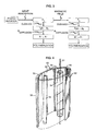
- FIG. 1 there is shown an apparatus which is designated generally by the numeral 20 and in which is used to draw optical fiber 21 from a specially prepared cylindrical preform 22 and for then coating the drawn fiber.
- the optical fiber 21 is formed by locally and symmetrically heating the preform 22, typically 7 to 25 mm in diameter and 60 cm in length, to a temperature of about 2000°C. As the preform is fed into and through a furnace 23, fiber 21 is drawn from the molten material.
- the elements of the draw system include the furnace 23 wherein the preform is drawn down to the fiber size after which the fiber 21 is pulled from a heat zone therein.
- the diameter of the fiber 21 is measured by a device 24 at a point shortly after the fiber is formed and this measured value becomes an input into a control system.
- the measured diameter is compared to the desired value and an output signal is generated to adjust the draw speed such that the fiber diameter approaches the desired value.
- a protective coating system 25 (see also FIG. 2) is applied to the fiber by an apparatus 27.
- Preservation of fiber strength requires the application of the protective coating, which shields newly drawn fiber from the deleterious effects of the atmosphere.
- This coating system must be applied in a manner that does not damage the surface of the fiber 21 and such that the fiber has a predetermined diameter and is protected from abrasion during subsequent manufacturing operations, installation and service. Minimizing attenuation requires the selection of a suitable coating material and a controlled application of it to the fiber.
- Such a coating apparatus may be one such as that described in priorly identified U.S. Patent 4,474,830.
- the coating materials After the coating materials have been applied to the drawn fiber, the coating materials must be cured. Accordingly, the optical fiber having the coating materials thereon is passed through a curing chamber 30 for curing the coating system and a device 32 for measuring the outer diameter of the coated fiber. Afterwards, it is moved through a capstan 34 and is spooled for testing and storage prior to subsequent cable operations.
- the coating system 25 comprising two coating materials is applied to the optical fiber.
- the coating system 25 includes an inner layer 42 (see FIG. 2) which often is referred to as a primary coating material and an outer layer 44 which often is referred to as a secondary coating material.
- the coating material of the inner layer which has a substantially lower modulus than that of the outer layer, is such that it prevents microbending of the optical glass fiber.
- the higher modulus outer layer provides mechanical protection for the drawn glass fiber.
- each of the coating materials is curable by being exposed to a portion of the light spectrum. It is commonplace to use ultraviolet light curable coating materials which are crosslinked by a free radical polymerization mechanism. Generally each of the coating materials includes an oligomer, a diluent and a photoinitiator. Also included may be additives such as, for example, antioxidants, adhesion promoters, ultraviolet (UV) light stabilizers, surfactants and shelf life stabilizers.
- a first step in such a polymerization mechanism is the absorption of incident ultraviolet irradiation by the photoinitiator constituent of each coating composition (see FIG. 3).
- the photoinitiator upon exposure to suitable light energy is promoted to an excited singlet state which is a precursor for a caged singlet radical pair.
- the photoinitiator of each coating material in its excited singlet state cleaves to produce a caged radical pair, which is usually in the spin paired or singlet state.
- the two radical fragments In order to initiate polymerization, the two radical fragments must diffuse apart from each other and react with other constituents of the fiber coating materials. The radicals must diffuse out of the cage.
- the radicals diffuse from one another and interact with coating material such as acrylates, for example, that can undergo free radical polymerization.
- coating material such as acrylates, for example, that can undergo free radical polymerization.
- Some of the photoinitiator in the excited singlet state is converted to a triplet state by a process which is referred to as intersystem crossing. This conversion results in a population of the excited triplet state.
- a triplet or spin parallel radical pair is formed. Radicals diffuse from one another to interact with materials such as acrylates, for example, that are capable of undergoing radical polymerization.
- radicals For polymerization to occur, radicals must move out of an associated cage by diffusion which is much faster for a triplet radical pair than for a singlet radical pair. Because the free electrons of radicals in the singlet radical pair are spin paired, they are poised to cause bonding. In contrast, free electrons in a triplet radical pair are spin parallel. Because spin parallel radicals repulse one another, their recombination is reduced. Also, because spin parallel or triplet radical pairs repulse one another, the rate of diffusion of the caged radicals produced from the excited triplet state on the right of FIG. 3 is higher than for the singlet stage. As a result, the photoinitiator radicals from the triplet radical pairs are more readily available to initiate polymerization. The diffusion rate of the triplet radicals from one another is enhanced to combine with other components to cause crosslinking.
- a rate determining step in the manufactue of optical fiber is the curing speed of the ultraviolet light curable coating materials.
- the cure speed of material systems which can undergo free radical polymerization, such as optical fiber coatings, for example, and hence the production rate of systems which can undergo free radical polymerization such as optical fiber coatings is enhanced greatly by the application of a magnetic field simultaneously with the irradiation curing of the coating layers.
- recombination in a triplet radical cage is not nearly as apt to occur as in a singlet radical cage.
- a more efficient escape of photoinitiator radicals from one another allows a more efficient initiation of polymerization.
- the diffusion and hence the polymerization is much more rapid from the triplet radical pair than from the singlet radical pair.
- the magnetic field enhances intersystem crossing from the singlet state to a triplet state.
- the magnetic field may be such as to provide a higher rate of intersystem crossing and thus serves to increase the concentration of free radicals.
- the polymerization of the coating materials is greatly enhanced by the exposure of the coating materials to a magnetic field simultaneously with exposure to light curing energy. As a result, the curing of the coating materials of the inner and outer layers is accelerated, which advantageously allows an increase in speed of the fiber draw line.
- the curing chamber 30 provides such enhanced curing of the coating material or materials.
- the curing chamber 30 (see FIG. 4) is provided with a housing 52.
- a quartz tube 54 Disposed within the housing 52 is a quartz tube 54 having a longitudinal axis 56 parallel to that of the housing.
- the quartz tube 54 is adapted to have the drawn optical fiber 21 moved therethrough and has an inner diameter of about 2.5 cm and a thickness of about 1 mm.
- an elongated quartz halogen lamp 58 which parallels the path of the optical fiber and which emits ultraviolet radiation that is used to cure the coating material or materials.
- the lamp 58 and the quartz tube 54 through which the fiber is moved are located at the focii of elliptical mirrors 59-59 to ensure that substantially all of the periphery of a moving optical fiber is impinged by light emitted by the lamp 58.
- the quartz tube 54 through which the optical fiber is moved is transparent to ultraviolet radiation from the lamp. Consequently, the use of such a tube does not impair the curing of the coating material on the moving optical fiber.
- the ultraviolet curing of the coating materials on the optical fiber is accomplished with energy in the wavelength range of about 200 to 400 nm.
- the magnet system 60 Positioned adjacent to the exterior of the curing chamber 30 is a magnet system 60.
- the magnet system may comprise two bar magnets 62-62 or electromagnets which are aligned with the quartz tube 54. Because the magnets are positioned outside the chamber 30, they do not interfere with the reflected light and hence do not impair the curing step.
- FIG. 5 there is shown a comparison of the equilibrium modulus of a UV curable ink achieved at different UV dose levels with and without the simultaneous application of a magnetic field.
- a curve designated 70 represents the plot for the curing of the coating materials without exposure to a magnetic field.
- a curve designated 72 represents the plot for the curing of the coating materials with the simultaneous exposure to a magnetic field.
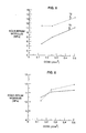
- FIGS. 6, 7, and 8 depict different equilibrium modulus levels of optical fiber UV curable coating materials at varying UV dose levels with and without the simultaneous exposure to a magnetic field.
- the broken lines at enhanced levels represent coating material subjected simultaneously to curing light energy and to a magnetic field.
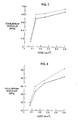
- Histograms in FIGS. 9 and 10 depict the percentage increase in equilibrium modulus of optical fiber coating materials with the simultaneous application of a magnetic field at varying UV dose levels.
- the histogram in FIG. 11 depicts the percentage increase in equilibrium modulus of a UV curable ink with the simultaneous application of a magnetic field.
Landscapes
- Chemical & Material Sciences (AREA)
- Health & Medical Sciences (AREA)
- Organic Chemistry (AREA)
- Life Sciences & Earth Sciences (AREA)
- Chemical Kinetics & Catalysis (AREA)
- Toxicology (AREA)
- Physics & Mathematics (AREA)
- Engineering & Computer Science (AREA)
- Materials Engineering (AREA)
- General Health & Medical Sciences (AREA)
- General Life Sciences & Earth Sciences (AREA)
- General Chemical & Material Sciences (AREA)
- Geochemistry & Mineralogy (AREA)
- Oral & Maxillofacial Surgery (AREA)
- Thermal Sciences (AREA)
- Electromagnetism (AREA)
- Surface Treatment Of Glass Fibres Or Filaments (AREA)
- Optical Fibers, Optical Fiber Cores, And Optical Fiber Bundles (AREA)
Applications Claiming Priority (2)
| Application Number | Priority Date | Filing Date | Title |
|---|---|---|---|
| US07/491,753 US5000772A (en) | 1990-03-09 | 1990-03-09 | Methods of and apparatus for making coated optical fiber |
| US491753 | 1990-03-09 |
Publications (3)
| Publication Number | Publication Date |
|---|---|
| EP0445980A2 true EP0445980A2 (fr) | 1991-09-11 |
| EP0445980A3 EP0445980A3 (en) | 1991-12-11 |
| EP0445980B1 EP0445980B1 (fr) | 1996-07-17 |
Family
ID=23953520
Family Applications (1)
| Application Number | Title | Priority Date | Filing Date |
|---|---|---|---|
| EP91301699A Expired - Lifetime EP0445980B1 (fr) | 1990-03-09 | 1991-03-01 | Procédés et dispositif de fabrication de fibres optiques revêtues |
Country Status (6)
| Country | Link |
|---|---|
| US (1) | US5000772A (fr) |
| EP (1) | EP0445980B1 (fr) |
| KR (1) | KR100195766B1 (fr) |
| CA (1) | CA2036743C (fr) |
| DE (1) | DE69120841T2 (fr) |
| DK (1) | DK0445980T3 (fr) |
Cited By (2)
| Publication number | Priority date | Publication date | Assignee | Title |
|---|---|---|---|---|
| EP0595538A1 (fr) * | 1992-10-30 | 1994-05-04 | AT&T Corp. | Appareil pour le durcissement de revêtements sur une fibre optique étirée |
| EP1236697A1 (fr) * | 2001-02-20 | 2002-09-04 | Shin-Etsu Chemical Co., Ltd. | Préparation de fibres optiques |
Families Citing this family (9)
| Publication number | Priority date | Publication date | Assignee | Title |
|---|---|---|---|---|
| US5147433A (en) * | 1990-02-15 | 1992-09-15 | At&T Bell Laboratories | Methods of making coated optical fiber |
| US5314519A (en) * | 1992-08-31 | 1994-05-24 | At&T Bell Laboratories | Methods and apparatus for increasing optical fiber draw speed |
| US5418369A (en) * | 1993-03-12 | 1995-05-23 | At&T Corp. | System for continuously monitoring curing energy levels within a curing unit |
| EP0894277A4 (fr) * | 1997-01-24 | 2002-07-31 | Borden Chem Inc | Fibres optiques traitees munies de revetements primaires pelables et procedes de fabrication et d'utilisation de ces dernieres |
| US6304704B1 (en) | 1999-07-27 | 2001-10-16 | Lucent Technologies Inc. | Mode mixing buffered optical fiber apparatus and method for making |
| US6304705B1 (en) | 1999-07-27 | 2001-10-16 | Lucent Technologies Inc. | Mode coupling buffered optical fiber apparatus and method for making |
| US7022382B1 (en) | 2000-06-16 | 2006-04-04 | Alcatel | UV-cure of coatings for an optical fiber with a laser |
| US9442007B2 (en) * | 2013-05-06 | 2016-09-13 | Phoseon Technology, Inc. | Method and system for monitoring ultraviolet light for a fiber cure system |
| US9442008B2 (en) * | 2013-05-06 | 2016-09-13 | Phoseon Technology, Inc. | Method and system for determining curing tube clarity |
Family Cites Families (7)
| Publication number | Priority date | Publication date | Assignee | Title |
|---|---|---|---|---|
| US4448657A (en) * | 1981-10-23 | 1984-05-15 | The Trustees Of Columbia University In The City Of New York | Methods employing magnetic fields for controlling emulsion polymerization |
| US4932750A (en) * | 1982-12-09 | 1990-06-12 | Desoto, Inc. | Single-coated optical fiber |
| SU1467072A1 (ru) * | 1986-02-12 | 1989-03-23 | Всесоюзный Научно-Исследовательский Проектно-Конструкторский Институт Технологии Электрических Машин Малой Мощности | Способ регулировани в зкости компаунда и устройство дл его осуществлени |
| US4863576A (en) * | 1986-09-04 | 1989-09-05 | Collins George J | Method and apparatus for hermetic coating of optical fibers |
| CA1337056C (fr) * | 1987-10-30 | 1995-09-19 | Bob J. Overton | Methodes et appareil de durcissement de revetements de fibre optique |
| US5019303A (en) * | 1988-05-11 | 1991-05-28 | Matsushita Electric Industrial Co., Ltd. | Process for producing polyacetylene |
| DE3913519C2 (de) * | 1989-04-25 | 1996-06-27 | Rheydt Kabelwerk Ag | UV-Aushärtesystem für optische Fasern |
-
1990
- 1990-03-09 US US07/491,753 patent/US5000772A/en not_active Expired - Lifetime
-
1991
- 1991-02-20 CA CA002036743A patent/CA2036743C/fr not_active Expired - Fee Related
- 1991-02-28 KR KR1019910003260A patent/KR100195766B1/ko not_active Expired - Fee Related
- 1991-03-01 EP EP91301699A patent/EP0445980B1/fr not_active Expired - Lifetime
- 1991-03-01 DE DE69120841T patent/DE69120841T2/de not_active Expired - Fee Related
- 1991-03-01 DK DK91301699.4T patent/DK0445980T3/da active
Cited By (3)
| Publication number | Priority date | Publication date | Assignee | Title |
|---|---|---|---|---|
| EP0595538A1 (fr) * | 1992-10-30 | 1994-05-04 | AT&T Corp. | Appareil pour le durcissement de revêtements sur une fibre optique étirée |
| EP1236697A1 (fr) * | 2001-02-20 | 2002-09-04 | Shin-Etsu Chemical Co., Ltd. | Préparation de fibres optiques |
| US6877344B2 (en) | 2001-02-20 | 2005-04-12 | Shin-Etsu Chemical Co., Ltd. | Preparation of optical fiber |
Also Published As
| Publication number | Publication date |
|---|---|
| DK0445980T3 (da) | 1996-08-12 |
| US5000772A (en) | 1991-03-19 |
| EP0445980A3 (en) | 1991-12-11 |
| DE69120841D1 (de) | 1996-08-22 |
| KR100195766B1 (ko) | 1999-06-15 |
| KR910016634A (ko) | 1991-11-05 |
| EP0445980B1 (fr) | 1996-07-17 |
| DE69120841T2 (de) | 1997-02-20 |
| CA2036743A1 (fr) | 1991-09-10 |
| CA2036743C (fr) | 1996-03-26 |
Similar Documents
| Publication | Publication Date | Title |
|---|---|---|
| EP0442658B1 (fr) | Fibre optique revêtue et méthodes de fabrication | |
| US4913859A (en) | Methods of curing optical fiber coatings | |
| US5219623A (en) | Methods of producing an article which includes a light energy cured coating material | |
| EP0445980B1 (fr) | Procédés et dispositif de fabrication de fibres optiques revêtues | |
| US5440660A (en) | Fiber optic microcable produced with fiber reinforced ultraviolet light cured resin and method for manufacturing same | |
| US6018605A (en) | Photoinitiator--tuned optical fiber and optical fiber ribbon and method of making the same | |
| US5092264A (en) | Apparatus for curing optical fiber coatings | |
| EP0218244B1 (fr) | Méthode de production d'une fibre optique | |
| US5217518A (en) | Apparatus for making coated optical fiber | |
| US5636307A (en) | Fiber optic microcable produced with radiation cured composite | |
| EP0646552B1 (fr) | Méthode pour le durcissement de revêtements sur un fibre optique à deux couches | |
| CN1360215A (zh) | 用于湿态到湿态涂敷的可紫外线固化的光纤敷层 | |
| EP0854022A1 (fr) | Durcissement de fibres optiques à deux étages | |
| JP7536670B2 (ja) | 光ファイバ心線の製造方法 | |
| CA1337056C (fr) | Methodes et appareil de durcissement de revetements de fibre optique | |
| US5147433A (en) | Methods of making coated optical fiber | |
| CA2106281C (fr) | Appareil pour durcir les revetements de fibres optiques etirees | |
| US4774104A (en) | Irradiation device, arrangement for and method of cladding a filamentary body | |
| EP2338854B1 (fr) | Procédé de purge de tubes à durcissement par UV | |
| JP4172062B2 (ja) | 線状体に紫外線硬化樹脂を被覆する方法 | |
| EP0636590A1 (fr) | Procédé d'amélioration de la résistance à l'arrachement de fibres optiques revêtues de polymère | |
| JPH05203850A (ja) | 光ファイバテープ心線の製造方法及び製造装置 | |
| JPH01191110A (ja) | 光ファイバ多芯テープの製造方法 | |
| JPS63233807A (ja) | 紫外線硬化樹脂の硬化方法 | |
| JPS59162151A (ja) | 光伝送用ガラスフアイバの樹脂被覆方法 |
Legal Events
| Date | Code | Title | Description |
|---|---|---|---|
| PUAI | Public reference made under article 153(3) epc to a published international application that has entered the european phase |
Free format text: ORIGINAL CODE: 0009012 |
|
| AK | Designated contracting states |
Kind code of ref document: A2 Designated state(s): DE DK FR GB |
|
| PUAL | Search report despatched |
Free format text: ORIGINAL CODE: 0009013 |
|
| AK | Designated contracting states |
Kind code of ref document: A3 Designated state(s): DE DK FR GB |
|
| 17P | Request for examination filed |
Effective date: 19920602 |
|
| 17Q | First examination report despatched |
Effective date: 19920910 |
|
| RAP3 | Party data changed (applicant data changed or rights of an application transferred) |
Owner name: AT&T CORP. |
|
| GRAH | Despatch of communication of intention to grant a patent |
Free format text: ORIGINAL CODE: EPIDOS IGRA |
|
| GRAA | (expected) grant |
Free format text: ORIGINAL CODE: 0009210 |
|
| AK | Designated contracting states |
Kind code of ref document: B1 Designated state(s): DE DK FR GB |
|
| REG | Reference to a national code |
Ref country code: DK Ref legal event code: T3 |
|
| GRAH | Despatch of communication of intention to grant a patent |
Free format text: ORIGINAL CODE: EPIDOS IGRA |
|
| REF | Corresponds to: |
Ref document number: 69120841 Country of ref document: DE Date of ref document: 19960822 |
|
| ET | Fr: translation filed | ||
| PLBE | No opposition filed within time limit |
Free format text: ORIGINAL CODE: 0009261 |
|
| STAA | Information on the status of an ep patent application or granted ep patent |
Free format text: STATUS: NO OPPOSITION FILED WITHIN TIME LIMIT |
|
| 26N | No opposition filed | ||
| PGFP | Annual fee paid to national office [announced via postgrant information from national office to epo] |
Ref country code: DK Payment date: 19991217 Year of fee payment: 10 |
|
| PG25 | Lapsed in a contracting state [announced via postgrant information from national office to epo] |
Ref country code: DK Free format text: LAPSE BECAUSE OF NON-PAYMENT OF DUE FEES Effective date: 20010301 |
|
| REG | Reference to a national code |
Ref country code: DK Ref legal event code: EBP |
|
| REG | Reference to a national code |
Ref country code: GB Ref legal event code: IF02 |
|
| PGFP | Annual fee paid to national office [announced via postgrant information from national office to epo] |
Ref country code: GB Payment date: 20040225 Year of fee payment: 14 |
|
| PG25 | Lapsed in a contracting state [announced via postgrant information from national office to epo] |
Ref country code: GB Free format text: LAPSE BECAUSE OF NON-PAYMENT OF DUE FEES Effective date: 20050301 |
|
| PGFP | Annual fee paid to national office [announced via postgrant information from national office to epo] |
Ref country code: FR Payment date: 20050830 Year of fee payment: 15 |
|
| PGFP | Annual fee paid to national office [announced via postgrant information from national office to epo] |
Ref country code: DE Payment date: 20050930 Year of fee payment: 15 |
|
| GBPC | Gb: european patent ceased through non-payment of renewal fee |
Effective date: 20050301 |
|
| PG25 | Lapsed in a contracting state [announced via postgrant information from national office to epo] |
Ref country code: DE Free format text: LAPSE BECAUSE OF NON-PAYMENT OF DUE FEES Effective date: 20061003 |
|
| REG | Reference to a national code |
Ref country code: FR Ref legal event code: ST Effective date: 20061130 |
|
| PG25 | Lapsed in a contracting state [announced via postgrant information from national office to epo] |
Ref country code: FR Free format text: LAPSE BECAUSE OF NON-PAYMENT OF DUE FEES Effective date: 20060331 |