EP0595538A1 - Appareil pour le durcissement de revêtements sur une fibre optique étirée - Google Patents
Appareil pour le durcissement de revêtements sur une fibre optique étirée Download PDFInfo
- Publication number
- EP0595538A1 EP0595538A1 EP93308339A EP93308339A EP0595538A1 EP 0595538 A1 EP0595538 A1 EP 0595538A1 EP 93308339 A EP93308339 A EP 93308339A EP 93308339 A EP93308339 A EP 93308339A EP 0595538 A1 EP0595538 A1 EP 0595538A1
- Authority
- EP
- European Patent Office
- Prior art keywords
- housing
- center tube
- disposed
- pivotally moveable
- elliptical chamber
- Prior art date
- Legal status (The legal status is an assumption and is not a legal conclusion. Google has not performed a legal analysis and makes no representation as to the accuracy of the status listed.)
- Granted
Links
Images


Classifications
-
- H—ELECTRICITY
- H05—ELECTRIC TECHNIQUES NOT OTHERWISE PROVIDED FOR
- H05B—ELECTRIC HEATING; ELECTRIC LIGHT SOURCES NOT OTHERWISE PROVIDED FOR; CIRCUIT ARRANGEMENTS FOR ELECTRIC LIGHT SOURCES, IN GENERAL
- H05B3/00—Ohmic-resistance heating
- H05B3/0033—Heating devices using lamps
- H05B3/0038—Heating devices using lamps for industrial applications
-
- B—PERFORMING OPERATIONS; TRANSPORTING
- B01—PHYSICAL OR CHEMICAL PROCESSES OR APPARATUS IN GENERAL
- B01J—CHEMICAL OR PHYSICAL PROCESSES, e.g. CATALYSIS OR COLLOID CHEMISTRY; THEIR RELEVANT APPARATUS
- B01J19/00—Chemical, physical or physico-chemical processes in general; Their relevant apparatus
- B01J19/08—Processes employing the direct application of electric or wave energy, or particle radiation; Apparatus therefor
- B01J19/12—Processes employing the direct application of electric or wave energy, or particle radiation; Apparatus therefor employing electromagnetic waves
- B01J19/122—Incoherent waves
- B01J19/123—Ultraviolet light
-
- B—PERFORMING OPERATIONS; TRANSPORTING
- B05—SPRAYING OR ATOMISING IN GENERAL; APPLYING FLUENT MATERIALS TO SURFACES, IN GENERAL
- B05C—APPARATUS FOR APPLYING FLUENT MATERIALS TO SURFACES, IN GENERAL
- B05C3/00—Apparatus in which the work is brought into contact with a bulk quantity of liquid or other fluent material
- B05C3/02—Apparatus in which the work is brought into contact with a bulk quantity of liquid or other fluent material the work being immersed in the liquid or other fluent material
- B05C3/12—Apparatus in which the work is brought into contact with a bulk quantity of liquid or other fluent material the work being immersed in the liquid or other fluent material for treating work of indefinite length
-
- B—PERFORMING OPERATIONS; TRANSPORTING
- B29—WORKING OF PLASTICS; WORKING OF SUBSTANCES IN A PLASTIC STATE IN GENERAL
- B29C—SHAPING OR JOINING OF PLASTICS; SHAPING OF MATERIAL IN A PLASTIC STATE, NOT OTHERWISE PROVIDED FOR; AFTER-TREATMENT OF THE SHAPED PRODUCTS, e.g. REPAIRING
- B29C35/00—Heating, cooling or curing, e.g. crosslinking or vulcanising; Apparatus therefor
- B29C35/02—Heating or curing, e.g. crosslinking or vulcanizing during moulding, e.g. in a mould
- B29C35/08—Heating or curing, e.g. crosslinking or vulcanizing during moulding, e.g. in a mould by wave energy or particle radiation
- B29C35/10—Heating or curing, e.g. crosslinking or vulcanizing during moulding, e.g. in a mould by wave energy or particle radiation for articles of indefinite length
-
- C—CHEMISTRY; METALLURGY
- C03—GLASS; MINERAL OR SLAG WOOL
- C03C—CHEMICAL COMPOSITION OF GLASSES, GLAZES OR VITREOUS ENAMELS; SURFACE TREATMENT OF GLASS; SURFACE TREATMENT OF FIBRES OR FILAMENTS MADE FROM GLASS, MINERALS OR SLAGS; JOINING GLASS TO GLASS OR OTHER MATERIALS
- C03C25/00—Surface treatment of fibres or filaments made from glass, minerals or slags
- C03C25/10—Coating
- C03C25/12—General methods of coating; Devices therefor
-
- F—MECHANICAL ENGINEERING; LIGHTING; HEATING; WEAPONS; BLASTING
- F26—DRYING
- F26B—DRYING SOLID MATERIALS OR OBJECTS BY REMOVING LIQUID THEREFROM
- F26B13/00—Machines and apparatus for drying fabrics, fibres, yarns, or other materials in long lengths, with progressive movement
- F26B13/001—Drying and oxidising yarns, ribbons or the like
- F26B13/002—Drying coated, e.g. enamelled, varnished, wires
-
- F—MECHANICAL ENGINEERING; LIGHTING; HEATING; WEAPONS; BLASTING
- F26—DRYING
- F26B—DRYING SOLID MATERIALS OR OBJECTS BY REMOVING LIQUID THEREFROM
- F26B3/00—Drying solid materials or objects by processes involving the application of heat
- F26B3/28—Drying solid materials or objects by processes involving the application of heat by radiation, e.g. from the sun
-
- H—ELECTRICITY
- H05—ELECTRIC TECHNIQUES NOT OTHERWISE PROVIDED FOR
- H05B—ELECTRIC HEATING; ELECTRIC LIGHT SOURCES NOT OTHERWISE PROVIDED FOR; CIRCUIT ARRANGEMENTS FOR ELECTRIC LIGHT SOURCES, IN GENERAL
- H05B6/00—Heating by electric, magnetic or electromagnetic fields
- H05B6/64—Heating using microwaves
- H05B6/80—Apparatus for specific applications
-
- B—PERFORMING OPERATIONS; TRANSPORTING
- B29—WORKING OF PLASTICS; WORKING OF SUBSTANCES IN A PLASTIC STATE IN GENERAL
- B29C—SHAPING OR JOINING OF PLASTICS; SHAPING OF MATERIAL IN A PLASTIC STATE, NOT OTHERWISE PROVIDED FOR; AFTER-TREATMENT OF THE SHAPED PRODUCTS, e.g. REPAIRING
- B29C35/00—Heating, cooling or curing, e.g. crosslinking or vulcanising; Apparatus therefor
- B29C35/02—Heating or curing, e.g. crosslinking or vulcanizing during moulding, e.g. in a mould
- B29C35/08—Heating or curing, e.g. crosslinking or vulcanizing during moulding, e.g. in a mould by wave energy or particle radiation
- B29C35/0805—Heating or curing, e.g. crosslinking or vulcanizing during moulding, e.g. in a mould by wave energy or particle radiation using electromagnetic radiation
- B29C2035/0827—Heating or curing, e.g. crosslinking or vulcanizing during moulding, e.g. in a mould by wave energy or particle radiation using electromagnetic radiation using UV radiation
-
- B—PERFORMING OPERATIONS; TRANSPORTING
- B29—WORKING OF PLASTICS; WORKING OF SUBSTANCES IN A PLASTIC STATE IN GENERAL
- B29L—INDEXING SCHEME ASSOCIATED WITH SUBCLASS B29C, RELATING TO PARTICULAR ARTICLES
- B29L2011/00—Optical elements, e.g. lenses, prisms
- B29L2011/0075—Light guides, optical cables
Definitions
- This invention relates to an apparatus for curing coatings on drawn optical fiber.
- optical fiber In the manufacture of optical fiber, an optical glass preform is suspended vertically and moved so that successive increments of length are moved into a furnace. As a result of the temperature within the furnace, optical fiber is able to be drawn from the leading end of the preform.
- the fiber is provided with one or more layers of coating material.
- the coating material is an ultraviolet light energy curable material. Consequently, after the coating material has been applied, the coating material is cured. Subsequently, the coated, drawn fiber is measured and taken up on a spool.
- the curing apparatus includes an elliptical reflector or housing having a curing lamp which extends longitudinally parallel to the path of the fiber.
- the lamp or bulb as it frequently is called is positioned at one of the focal points of the elliptical reflector.
- the bulb emits radiation toward a longitudinally extending center tube, the center of which is positioned at the focal point of another portion of the elliptical housing aligned with the portion of the housing in which the bulb is positioned.
- the drawn optical fiber is advanced through the center tube and radiation from the bulb passes through the center tube to engage the fiber and cure the coating material. Radiation which scatters to the interior surface of the elliptical housing is reflected back into engagement with the fiber which is being moved along a path coincident with the loci of the focal points of successive sections of the reflector.
- a blanket of an inert gas is caused to become disposed about the coated, drawn fiber as it is advanced through the center tube. This is done in order to facilitate surface curing of the coating materials. Otherwise, any oxygen which is present inhibits the curing of the coating material.
- the optical fiber off-gases and clouds the tube.
- the amount of radiation which reaches the fiber is reduced until a point is reached when substantially only a portion of the radiation gets through to the fiber. Accordingly, it becomes necessary periodically to change the center tube in order to maintain a consistent cure level.
- the elliptical housing, the center tube and the bulb are disposed in the hinged enclosure having openings at the top and bottom thereof.
- the center tube is moved in a longitudinal direction slidably upwardly or downwardly out of the enclosure and a replacement center tube moved into its place.
- the existing center tube replacement process presents some practical problems.
- the optical fiber drawing line is oriented so that the fiber path is vertical and the preform is suspended vertically.
- the drawing line include a furnace, apparatus for the application of coating materials and curing apparatus, but also it includes apparatus for performing various measurements on the drawn and on the coated fiber.
- space on the line is at a premium.
- the enclosure In order to gain access to the center tube, the enclosure is moved partially so that a production technician can extend hands into the enclosure and move the center tube longitudinally vertically.
- an additional length of space must be provided above or below the curing apparatus or the curing apparatus must be dismantled substantially. This of course detracts from space available for other processes, given that there is a limited amount of space between a floor and a ceiling which can be occupied by a draw tower.
- the bulbs need to be cooled during operation, typically with a high flow rate of air.
- Exhaust ducts are attached to the enclosure and lead to fans which pull out the air. These are aligned vertically in sections and associated with each section is an exhaust duct system. In the past, these exhaust ducts have had to be removed from the enclosure prior to the pivotal movement of the enclosure and the removal of the interior center tube.
- an enclosure which enclosure facilitates replacement of a center tube without the need for additional space above or below the enclosure or without the severe dismantling of the curing apparatus.
- the sought-after enclosure must be such that it does not interfere with the present alignment of elements of the curing apparatus and desirably is such that the exhaust system need not be disassembled from the curing apparatus prior to replacement of the center tube.
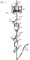
- FIG. 1 there is shown an apparatus which is designated generally by the numeral 20 and in which is used to draw optical fiber 21 from a specially prepared cylindrical preform 22 and for then coating the drawn fiber.
- the optical fiber 21 is formed by locally and symmetrically heating the preform 22, typically 20 to 40 mm in diameter and 80 cm in length, to a temperature of about 2000°C.
- fiber 21 is drawn from the molten material.
- the elements of the draw system include the furnace 23 wherein the preform is drawn down to the fiber size after which the fiber 21 is pulled from a heat zone therein.
- the diameter of the fiber 21 is measured by a device 24 at a point shortly after the fiber is formed and this measured value becomes an input into a control system.
- the measured diameter is compared to the desired value and an output signal is generated to adjust the draw speed such that the fiber diameter approaches the desired value.
- a protective coating system 25 (see also FIG. 2) is applied to the fiber by an apparatus 27.
- Preservation of fiber strength requires the application of the protective coating, which shields newly drawn fiber from the deleterious effects of the atmosphere.
- This coating system must be applied in a manner that does not damage the surface of the fiber 21 and such that the fiber has a predetermined diameter and is protected from abrasion during subsequent manufacturing operations, installation and service. Minimizing attenuation requires the selection of a suitable coating material and a controlled application of it to the fiber.
- Such a coating apparatus may be one such as that described in U.S. Patent 4,474,830.
- the coating materials After the coating materials have been applied to the drawn fiber, the coating materials must be cured. Accordingly, the optical fiber having the coating materials thereon is passed through a curing chamber 30 for curing the coating system and a device 32 for measuring the outer diameter of the coated fiber. Afterwards, it is moved through a capstan 34 and is spooled for testing and storage prior to subsequent cable operations.
- the protective coating system 25 comprising one or more layers of coating materials is applied to the optical fiber.
- the protective coating system 25 (shown in FIG. 2) includes an inner layer 42 which often is referred to as a primary coating material and an outer layer 44 which often is referred to as a secondary coating material.
- the coating material of the inner layer which has a substantially lower modulus than that of the outer layer, is such that it prevents microbending of the optical glass fiber.
- the higher modulus outer layer provides mechanical protection for the drawn glass fiber.
- each of the coating materials is curable by being exposed to a portion of the light spectrum. It is commonplace to use ultraviolet light curable coating materials which are crosslinked by a free radical polymerization mechanism. Generally each of the coating materials includes an oligomer, a diluent and a photoinitiator. Also included may be additives such as, for example, antioxidants, adhesion promoters, ultraviolet (UV) light stabilizers, surfactants and shelf life stabilizers.
- the curing chamber 30 provides such enhanced curing of the coating material or materials.
- the curing chamber 30 (see FIG. 3) is provided with an elliptical housing 52.
- a quartz tube 54 Disposed within the housing 52 is a quartz tube 54 having a longitudinal axis 56 parallel to that of the housing.
- the quartz tube 54 is adapted to have the drawn optical fiber 21 moved therethrough and has an inner diameter of about 2.5 cm and a thickness of about 1 mm.
- an elongated quartz halogen lamp 58 which parallels the path of the optical fiber and which emits ultraviolet radiation that is used to cure the coating material or materials.
- the lamp 58 and the quartz tube 54 through which the fiber is moved are located at the focii of elliptical mirrors 59-59 to ensure that substantially all of the periphery of a moving optical fiber is impinged by light emitted by the lamp 58.
- the quartz tube 54 through which the optical fiber is moved, is transparent to ultraviolet radiation from the lamp. Consequently, the use of such a tube does not impair the curing of the coating material on the moving optical fiber.
- the ultraviolet curing of the coating materials on the optical fiber is accomplished with energy in the wavelength range of about 200 to 400 nm.
- a curing apparatus on a fiber draw line includes more than one bulb with multiple bulbs being aligned longitudinally.
- such an arrangement may include multiple center tubes.
- the enclosure of the present invention includes a housing 62 which in end section is rectangularly shaped and which generally comprises two or more stacked sections.
- the housing 62 includes an end frame 64 (see FIG. 5) and side frames 66-66, a base plate 68 and a cover 69.
- the end frame 61 and the side frames 66-66 extend between the base and the cover.
- Disposed in the housing 62 is one portion 59 of the elliptical chamber, the portion in which is disposed the bulb 58.
- the portion 59 along free longitudinal edges is provided with flanges 72-72 (see FIG.
- Supporting an exhaust plenum 81 for the room air are three gusset plate assemblies 82, 84 and 86, each of which includes a triangular-shaped portion.
- the topmost two gusset plates are triangularly shaped and have semi-circular openings 83 and 85 formed therein.
- a lowermost gusset plate assembly includes a triangular plate 86 having a semi-circular opening 87 therein and a rectangular plate 88 having a circular opening 89 therein.
- a vertical stringer 91 spans from the top to the bottom gusset plates.
- the stringer 91 includes a longitudinal edge surface 93.
- the exhaust plenum 81 includes openings 90-90 each of which is aligned with an opening 79 in the end frame 64.
- the enclosure 62 also includes a pivotally moveable portion 95 which includes hinge portions 97-97 which are assembled to the hinge portions on the end frame 64 at hinges 80-80.
- the portion 95 includes a series of frame members 99-98 to support sidewalls 103-103.
- a rear wall 105 spans between the sidewall 103-103.
- a plate 107 which is adapted to be moved slidably under the topmost gusset plate assembly 82 of the housing 62 when the pivotally moveable portion is closed on the housing 62.
- the top portion also includes a trapezoidal portion 109 having semi-circular opening 111 therein.
- the semi-circular opening 111 cooperates with the semi-circular opening 83 to provide a circular opening.
- semi-circular openings 113 and 115 in plate portions 117 and 119 of the pivotally moveable portion 95 cooperate with the semi-circular openings 85 and 87 to provide circular openings.
- the center tube 54 which is not shown in FIG. 4 is inserted to span between the same semi-circular openings 83 and 85 and between the semi-circular openings 85 and 87 and the circular opening 89.
- the center tube 54 Prior to that insertion, the center tube 54 is provided with gasket-sealing material so that when the pivotally moveable portion is closed on the housing 62, a seal is provided about the center tube 54 where the center tube passes through the gusset plate assemblies. Also, when the pivotally moveable portion is closed on the housing 62, portions thereof having sealing material adhered thereto engage the longitudinal edge surface 93 of the stringer 91 (see FIG. 5) to form a seal.
- Magnetrons (not shown) adapted to provide suitable excitation for the bulbs 58-58 (see FIG. 3) are moved slidably into the housing from a rear portion thereof along guide rails 123-123 and 125-125.
- the lowermost rails 125-125 are shown provided with a plate 126 for holding magnetron apparatus, a curing bulb and one portion of the elliptical housing 52.
- the rails 123-123 also would be provided with such a plate. This facilitates the positioning of the magnetrons substantially close to the portions of the elliptical chambers disposed within the housing 62 and hence substantially close to the bulbs.
- Drawn optical fiber is moved through the center tube 54 and an inert gas such as nitrogen is moved into a lower end of the center tube, flowed therealong and exhausted at the top of the tube by a separate exhaust system (not shown). Also, room air is pulled by fans (not shown) through filters (not shown), across the magnetrons, through the elliptical chamber, through the openings 79-79 and 90-90, and out the exhaust system 81.
- an inert gas such as nitrogen is moved into a lower end of the center tube, flowed therealong and exhausted at the top of the tube by a separate exhaust system (not shown).
- room air is pulled by fans (not shown) through filters (not shown), across the magnetrons, through the elliptical chamber, through the openings 79-79 and 90-90, and out the exhaust system 81.
- the apparatus 60 is advantageous over enclosures of the prior art. Because of the pivotally moveable portion 95, the enclosure may be opened to permit the center tube or tubes to be exposed and removed laterally instead of longitudinally as required in the past. This of course results in less space needed on the draw line or, if already provided, can be used for other purposes. This is apparent from a comparison of FIGS. 4 and 6. As will be recalled, FIG. 4 depicts the arrangement of this invention with the center tube 54 adapted to be disposed in the openings 83, 85 and 87. When the pivotally moveable portion 95 is moved to the position shown in FIG. 4. the center tube 54 is exposed and a production technician may easily replace it.
- FIG. 6 which typifies prior art curing apparatus, a portion 59 of the housing 52 which includes the bulb 58 is disposed within a stationary enclosure 131.
- the other portion 59 of the housing 52 is disposed within a moveable enclosure 133 which is pivotally moveable about a pivot point 135.
- the pivotal movement of the portion 133 to the position shown in FIG. 6 does not allow freedom of movement laterally of the center tube 54.
- the center tube 54 continues to be captured in circular openings along the height of the moveable enclosure thereby necessitating longitudinal movement to replace it.
- portions 137-137 project from the top and bottom of the pivotally moveable portion 133 (only the top portion 137 being visible in FIG. 6).
- the portions 137-137 overlap the portion 131 when the portion 133 is moved pivotally to cause the elliptical housing portion in the stationary enclosure 131 to abut its mating elliptical housing portion in the pivotally moveable portion 133.
- the prior art curing apparatus shown in FIG. 6 contrasts with the arrangement of this invention. Specifically, in the present invention the pivotal movement of a portion of the enclosure removes a portion of the enclosing wall of an opening in which the center tube is disposed, thereby allowing lateral movement of the center tube for replacement purposes.
- the exhaust system may remain in place attached to the gusset plates while the pivotally moveable portion is swung open giving access to the center tube or tubes thereby facilitating removal.
- the magnetrons, bulbs and portion of the elliptical housing may be moved slidably along the plates on the guide rails 123-123 and 125-125.
- the arrangement is such that the magnetrons may be moved into justaposition with the other portion of the elliptical housing.
- the magnetrons, the bulbs, the elliptical chamber, the center tube and the exhaust system all are supported from the base plate 68.
- a production technician causes the base plate to be moved in x and y directions to correct the misalignment. This may be accomplished by mounting the base plate on an x-y positioner (not shown). Further, the positioner may be provided with the capability of adjusting the orientation in the z direction thereby providing the capability of angular alignment of the reflectors and the optical fiber. Finally, the door to open is smaller, which helps the alignment process.
Landscapes
- Engineering & Computer Science (AREA)
- Chemical & Material Sciences (AREA)
- Life Sciences & Earth Sciences (AREA)
- Health & Medical Sciences (AREA)
- Physics & Mathematics (AREA)
- Electromagnetism (AREA)
- Toxicology (AREA)
- Organic Chemistry (AREA)
- Chemical Kinetics & Catalysis (AREA)
- Textile Engineering (AREA)
- General Engineering & Computer Science (AREA)
- Mechanical Engineering (AREA)
- General Life Sciences & Earth Sciences (AREA)
- General Chemical & Material Sciences (AREA)
- Geochemistry & Mineralogy (AREA)
- Materials Engineering (AREA)
- Microbiology (AREA)
- General Health & Medical Sciences (AREA)
- Thermal Sciences (AREA)
- Oral & Maxillofacial Surgery (AREA)
- Surface Treatment Of Glass Fibres Or Filaments (AREA)
- Optical Fibers, Optical Fiber Cores, And Optical Fiber Bundles (AREA)
Applications Claiming Priority (2)
| Application Number | Priority Date | Filing Date | Title |
|---|---|---|---|
| US969665 | 1992-10-30 | ||
| US07/969,665 US5294260A (en) | 1992-10-30 | 1992-10-30 | Apparatus for curing coatings on drawn optical fiber |
Publications (2)
| Publication Number | Publication Date |
|---|---|
| EP0595538A1 true EP0595538A1 (fr) | 1994-05-04 |
| EP0595538B1 EP0595538B1 (fr) | 1997-06-18 |
Family
ID=25515829
Family Applications (1)
| Application Number | Title | Priority Date | Filing Date |
|---|---|---|---|
| EP93308339A Expired - Lifetime EP0595538B1 (fr) | 1992-10-30 | 1993-10-20 | Appareil pour le durcissement de revêtements sur une fibre optique étirée |
Country Status (8)
| Country | Link |
|---|---|
| US (1) | US5294260A (fr) |
| EP (1) | EP0595538B1 (fr) |
| JP (1) | JP2669777B2 (fr) |
| AU (1) | AU657875B2 (fr) |
| CA (1) | CA2106281C (fr) |
| DE (1) | DE69311673T2 (fr) |
| MX (1) | MX9306605A (fr) |
| NZ (1) | NZ250053A (fr) |
Families Citing this family (12)
| Publication number | Priority date | Publication date | Assignee | Title |
|---|---|---|---|---|
| FI90381C (fi) * | 1992-06-18 | 1994-01-25 | Maillefer Nokia Holding | Menetelmä ja sovitelma optisten kuitujen värjäämiseksi |
| FI102421B (fi) * | 1996-04-04 | 1998-11-30 | Nextrom Holding Sa | Sovitelma kuitujen, ribbonin tai filamenttien jatkokäsittelyn yhteydes sä |
| US6242717B1 (en) * | 1999-08-30 | 2001-06-05 | Lucent Technologies Inc. | Removable reflector rack for an ultraviolet curing oven |
| US6372047B1 (en) * | 1999-12-29 | 2002-04-16 | Lucent Technologies Inc. | Process and apparatus for dip recoating of optical fibers |
| DE102007061044A1 (de) * | 2007-12-18 | 2009-06-25 | Advanced Photonics Technologies Ag | Strahlungstrockner |
| US7923706B2 (en) * | 2008-10-03 | 2011-04-12 | Nordson Corporation | Ultraviolet curing apparatus for continuous material |
| US9442007B2 (en) * | 2013-05-06 | 2016-09-13 | Phoseon Technology, Inc. | Method and system for monitoring ultraviolet light for a fiber cure system |
| JP6379118B2 (ja) | 2016-01-10 | 2018-08-22 | Hoya Candeo Optronics株式会社 | 光照射装置 |
| JP6631799B2 (ja) * | 2016-07-05 | 2020-01-15 | ウシオ電機株式会社 | 光照射装置 |
| JP6660317B2 (ja) | 2017-01-31 | 2020-03-11 | Hoya Candeo Optronics株式会社 | 光照射装置 |
| CN107930904B (zh) * | 2017-10-16 | 2019-07-09 | 重庆七彩虹新材料技术有限公司 | 一种喷漆流水线的板材防雾喷漆机构 |
| CN111487730B (zh) * | 2020-04-14 | 2022-04-22 | 浙江超前通信科技股份有限公司 | 可根据施工环境改变扩容方向的高容量扩容光缆交接箱 |
Citations (4)
| Publication number | Priority date | Publication date | Assignee | Title |
|---|---|---|---|---|
| GB2168230A (en) * | 1984-11-29 | 1986-06-11 | Sumitomo Electric Industries | Apparatus for curing UV-curable resin |
| FR2629187A1 (fr) * | 1988-03-24 | 1989-09-29 | France Etat | Four a rayonnement ultraviolet pour la polymerisation de revetements photopolymerisables |
| JPH02263740A (ja) * | 1981-06-03 | 1990-10-26 | Sumitomo Electric Ind Ltd | 光ファイバー線の線引方法および装置 |
| EP0445980A2 (fr) * | 1990-03-09 | 1991-09-11 | AT&T Corp. | Procédés et dispositif de fabrication de fibres optiques revêtues |
Family Cites Families (4)
| Publication number | Priority date | Publication date | Assignee | Title |
|---|---|---|---|---|
| US4474830A (en) * | 1982-12-29 | 1984-10-02 | At&T Bell Laboratories | Multiple coating of fibers |
| US5147433A (en) * | 1990-02-15 | 1992-09-15 | At&T Bell Laboratories | Methods of making coated optical fiber |
| US5015068A (en) * | 1990-02-15 | 1991-05-14 | At&T Bell Laboratories | Coated optical fiber and methods of making |
| US5217518A (en) * | 1990-03-09 | 1993-06-08 | At&T Bell Laboratories | Apparatus for making coated optical fiber |
-
1992
- 1992-10-30 US US07/969,665 patent/US5294260A/en not_active Expired - Fee Related
-
1993
- 1993-09-15 CA CA002106281A patent/CA2106281C/fr not_active Expired - Fee Related
- 1993-10-20 DE DE69311673T patent/DE69311673T2/de not_active Expired - Fee Related
- 1993-10-20 EP EP93308339A patent/EP0595538B1/fr not_active Expired - Lifetime
- 1993-10-22 AU AU50231/93A patent/AU657875B2/en not_active Ceased
- 1993-10-25 MX MX9306605A patent/MX9306605A/es not_active IP Right Cessation
- 1993-10-26 NZ NZ250053A patent/NZ250053A/en unknown
- 1993-10-29 JP JP5292377A patent/JP2669777B2/ja not_active Expired - Fee Related
Patent Citations (4)
| Publication number | Priority date | Publication date | Assignee | Title |
|---|---|---|---|---|
| JPH02263740A (ja) * | 1981-06-03 | 1990-10-26 | Sumitomo Electric Ind Ltd | 光ファイバー線の線引方法および装置 |
| GB2168230A (en) * | 1984-11-29 | 1986-06-11 | Sumitomo Electric Industries | Apparatus for curing UV-curable resin |
| FR2629187A1 (fr) * | 1988-03-24 | 1989-09-29 | France Etat | Four a rayonnement ultraviolet pour la polymerisation de revetements photopolymerisables |
| EP0445980A2 (fr) * | 1990-03-09 | 1991-09-11 | AT&T Corp. | Procédés et dispositif de fabrication de fibres optiques revêtues |
Non-Patent Citations (1)
| Title |
|---|
| CHEMICAL ABSTRACTS, vol. 114, no. 26, 1 July 1991, Columbus, Ohio, US; abstract no. 252497w, page 331; * |
Also Published As
| Publication number | Publication date |
|---|---|
| AU5023193A (en) | 1994-05-12 |
| DE69311673D1 (de) | 1997-07-24 |
| US5294260A (en) | 1994-03-15 |
| NZ250053A (en) | 1995-09-26 |
| MX9306605A (es) | 1994-04-29 |
| CA2106281C (fr) | 1997-02-04 |
| JP2669777B2 (ja) | 1997-10-29 |
| EP0595538B1 (fr) | 1997-06-18 |
| CA2106281A1 (fr) | 1994-05-01 |
| DE69311673T2 (de) | 1998-01-22 |
| AU657875B2 (en) | 1995-03-23 |
| JPH0772358A (ja) | 1995-03-17 |
Similar Documents
| Publication | Publication Date | Title |
|---|---|---|
| EP0595538B1 (fr) | Appareil pour le durcissement de revêtements sur une fibre optique étirée | |
| US7785092B2 (en) | Systems and methods for producing contact lenses from a polymerizable composition | |
| CN104114802B (zh) | 用于真空绝缘玻璃vig单元脱焊装置的光源解决方案和/或相关方法 | |
| EP1216968B1 (fr) | Dispositif pour le durcissement aux rayons ultraviolets et méthode | |
| RU2487839C2 (ru) | Отверждение волокна протяженными излучателями | |
| EP0442658B1 (fr) | Fibre optique revêtue et méthodes de fabrication | |
| EP1216969A1 (fr) | Revêtements pour fibres optiques durcissables par rayons ultraviolets pour application humide sur humide | |
| EP0854022A1 (fr) | Durcissement de fibres optiques à deux étages | |
| US5219623A (en) | Methods of producing an article which includes a light energy cured coating material | |
| EP0646552B1 (fr) | Méthode pour le durcissement de revêtements sur un fibre optique à deux couches | |
| EP0445980B1 (fr) | Procédés et dispositif de fabrication de fibres optiques revêtues | |
| JP2022514475A (ja) | 拡散反射器および使用方法 | |
| US5217518A (en) | Apparatus for making coated optical fiber | |
| KR101864111B1 (ko) | 자외선 광을 발생시키기 위한 램프 시스템들 및 방법들 | |
| KR20200136626A (ko) | 반도체 표면처리용 스테이지 챔버 및 이를 구비한 반도체 표면처리 장치 | |
| US5147433A (en) | Methods of making coated optical fiber | |
| KR20190037939A (ko) | 에너지 효율이 개선된 반사갓 승강형 uv경화장치 | |
| US20240103214A1 (en) | Thermally annealed gratings in coated fiber and related systems and methods | |
| JP2578256Y2 (ja) | 光ファイバーに塗布されたコーティング剤の硬化装置 | |
| JP2002303085A (ja) | ブラインドのラダーコード製造方法 | |
| JPH04295032A (ja) | 光ファイバーに塗布されたコーティング剤の硬化装置 | |
| SU543914A2 (ru) | Устройство дл контактной фотопечати | |
| RU1776572C (ru) | Установка дл отверждени полимерного материала | |
| JPH0255249A (ja) | 光ファイバに塗布されたコーティング材の硬化装置 | |
| HK1121106B (en) | Systems and methods for producing silicone hydrogel contact lenses from a polymerizable composition |
Legal Events
| Date | Code | Title | Description |
|---|---|---|---|
| PUAI | Public reference made under article 153(3) epc to a published international application that has entered the european phase |
Free format text: ORIGINAL CODE: 0009012 |
|
| AK | Designated contracting states |
Kind code of ref document: A1 Designated state(s): DE FR GB |
|
| RAP3 | Party data changed (applicant data changed or rights of an application transferred) |
Owner name: AT&T CORP. |
|
| 17P | Request for examination filed |
Effective date: 19941021 |
|
| 17Q | First examination report despatched |
Effective date: 19951123 |
|
| GRAG | Despatch of communication of intention to grant |
Free format text: ORIGINAL CODE: EPIDOS AGRA |
|
| GRAH | Despatch of communication of intention to grant a patent |
Free format text: ORIGINAL CODE: EPIDOS IGRA |
|
| GRAH | Despatch of communication of intention to grant a patent |
Free format text: ORIGINAL CODE: EPIDOS IGRA |
|
| GRAA | (expected) grant |
Free format text: ORIGINAL CODE: 0009210 |
|
| AK | Designated contracting states |
Kind code of ref document: B1 Designated state(s): DE FR GB |
|
| REF | Corresponds to: |
Ref document number: 69311673 Country of ref document: DE Date of ref document: 19970724 |
|
| ET | Fr: translation filed | ||
| PLBE | No opposition filed within time limit |
Free format text: ORIGINAL CODE: 0009261 |
|
| 26N | No opposition filed | ||
| REG | Reference to a national code |
Ref country code: GB Ref legal event code: IF02 |
|
| PGFP | Annual fee paid to national office [announced via postgrant information from national office to epo] |
Ref country code: FR Payment date: 20021002 Year of fee payment: 10 |
|
| PGFP | Annual fee paid to national office [announced via postgrant information from national office to epo] |
Ref country code: GB Payment date: 20021016 Year of fee payment: 10 |
|
| PGFP | Annual fee paid to national office [announced via postgrant information from national office to epo] |
Ref country code: DE Payment date: 20021031 Year of fee payment: 10 |
|
| PG25 | Lapsed in a contracting state [announced via postgrant information from national office to epo] |
Ref country code: GB Free format text: LAPSE BECAUSE OF NON-PAYMENT OF DUE FEES Effective date: 20031020 |
|
| PG25 | Lapsed in a contracting state [announced via postgrant information from national office to epo] |
Ref country code: DE Free format text: LAPSE BECAUSE OF NON-PAYMENT OF DUE FEES Effective date: 20040501 |
|
| GBPC | Gb: european patent ceased through non-payment of renewal fee |
Effective date: 20031020 |
|
| PG25 | Lapsed in a contracting state [announced via postgrant information from national office to epo] |
Ref country code: FR Free format text: LAPSE BECAUSE OF NON-PAYMENT OF DUE FEES Effective date: 20040630 |
|
| REG | Reference to a national code |
Ref country code: FR Ref legal event code: ST |