EP0445988A2 - Gerät zum Bearbeiten von sphärischen Flächen und dazugehörige Fördereinrichtung - Google Patents
Gerät zum Bearbeiten von sphärischen Flächen und dazugehörige Fördereinrichtung Download PDFInfo
- Publication number
- EP0445988A2 EP0445988A2 EP91301726A EP91301726A EP0445988A2 EP 0445988 A2 EP0445988 A2 EP 0445988A2 EP 91301726 A EP91301726 A EP 91301726A EP 91301726 A EP91301726 A EP 91301726A EP 0445988 A2 EP0445988 A2 EP 0445988A2
- Authority
- EP
- European Patent Office
- Prior art keywords
- cam
- grinding plate
- spherical
- cam follower
- transporting
- Prior art date
- Legal status (The legal status is an assumption and is not a legal conclusion. Google has not performed a legal analysis and makes no representation as to the accuracy of the status listed.)
- Granted
Links
- 238000003754 machining Methods 0.000 title claims abstract description 35
- 239000000463 material Substances 0.000 claims abstract description 40
- 230000003287 optical effect Effects 0.000 claims abstract description 20
- 238000003825 pressing Methods 0.000 claims description 4
- 238000000034 method Methods 0.000 description 12
- 229910003460 diamond Inorganic materials 0.000 description 6
- 239000010432 diamond Substances 0.000 description 6
- 238000005520 cutting process Methods 0.000 description 4
- 239000008188 pellet Substances 0.000 description 4
- 238000005498 polishing Methods 0.000 description 4
- 230000032258 transport Effects 0.000 description 4
- 238000010276 construction Methods 0.000 description 3
- 238000010586 diagram Methods 0.000 description 3
- 230000000694 effects Effects 0.000 description 2
- 230000003028 elevating effect Effects 0.000 description 2
- 238000004519 manufacturing process Methods 0.000 description 2
- 238000007781 pre-processing Methods 0.000 description 2
- 238000005299 abrasion Methods 0.000 description 1
- 230000001747 exhibiting effect Effects 0.000 description 1
- 238000012805 post-processing Methods 0.000 description 1
- 238000012545 processing Methods 0.000 description 1
- 238000009877 rendering Methods 0.000 description 1
Images






Classifications
-
- B—PERFORMING OPERATIONS; TRANSPORTING
- B23—MACHINE TOOLS; METAL-WORKING NOT OTHERWISE PROVIDED FOR
- B23Q—DETAILS, COMPONENTS, OR ACCESSORIES FOR MACHINE TOOLS, e.g. ARRANGEMENTS FOR COPYING OR CONTROLLING; MACHINE TOOLS IN GENERAL CHARACTERISED BY THE CONSTRUCTION OF PARTICULAR DETAILS OR COMPONENTS; COMBINATIONS OR ASSOCIATIONS OF METAL-WORKING MACHINES, NOT DIRECTED TO A PARTICULAR RESULT
- B23Q35/00—Control systems or devices for copying directly from a pattern or a master model; Devices for use in copying manually
- B23Q35/04—Control systems or devices for copying directly from a pattern or a master model; Devices for use in copying manually using a feeler or the like travelling along the outline of the pattern, model or drawing; Feelers, patterns, or models therefor
- B23Q35/08—Means for transforming movement of the feeler or the like into feed movement of tool or work
- B23Q35/10—Means for transforming movement of the feeler or the like into feed movement of tool or work mechanically only
- B23Q35/101—Means for transforming movement of the feeler or the like into feed movement of tool or work mechanically only with a pattern composed of one or more lines used simultaneously for one tool
- B23Q35/105—Means for transforming movement of the feeler or the like into feed movement of tool or work mechanically only with a pattern composed of one or more lines used simultaneously for one tool of two lines
-
- B—PERFORMING OPERATIONS; TRANSPORTING
- B23—MACHINE TOOLS; METAL-WORKING NOT OTHERWISE PROVIDED FOR
- B23Q—DETAILS, COMPONENTS, OR ACCESSORIES FOR MACHINE TOOLS, e.g. ARRANGEMENTS FOR COPYING OR CONTROLLING; MACHINE TOOLS IN GENERAL CHARACTERISED BY THE CONSTRUCTION OF PARTICULAR DETAILS OR COMPONENTS; COMBINATIONS OR ASSOCIATIONS OF METAL-WORKING MACHINES, NOT DIRECTED TO A PARTICULAR RESULT
- B23Q1/00—Members which are comprised in the general build-up of a form of machine, particularly relatively large fixed members
- B23Q1/25—Movable or adjustable work or tool supports
- B23Q1/44—Movable or adjustable work or tool supports using particular mechanisms
- B23Q1/50—Movable or adjustable work or tool supports using particular mechanisms with rotating pairs only, the rotating pairs being the first two elements of the mechanism
- B23Q1/54—Movable or adjustable work or tool supports using particular mechanisms with rotating pairs only, the rotating pairs being the first two elements of the mechanism two rotating pairs only
- B23Q1/5468—Movable or adjustable work or tool supports using particular mechanisms with rotating pairs only, the rotating pairs being the first two elements of the mechanism two rotating pairs only a single rotating pair followed parallelly by a single rotating pair
-
- B—PERFORMING OPERATIONS; TRANSPORTING
- B24—GRINDING; POLISHING
- B24B—MACHINES, DEVICES, OR PROCESSES FOR GRINDING OR POLISHING; DRESSING OR CONDITIONING OF ABRADING SURFACES; FEEDING OF GRINDING, POLISHING, OR LAPPING AGENTS
- B24B11/00—Machines or devices designed for grinding spherical surfaces or parts of spherical surfaces on work; Accessories therefor
-
- B—PERFORMING OPERATIONS; TRANSPORTING
- B24—GRINDING; POLISHING
- B24B—MACHINES, DEVICES, OR PROCESSES FOR GRINDING OR POLISHING; DRESSING OR CONDITIONING OF ABRADING SURFACES; FEEDING OF GRINDING, POLISHING, OR LAPPING AGENTS
- B24B13/00—Machines or devices designed for grinding or polishing optical surfaces on lenses or surfaces of similar shape on other work; Accessories therefor
- B24B13/06—Machines or devices designed for grinding or polishing optical surfaces on lenses or surfaces of similar shape on other work; Accessories therefor grinding of lenses, the tool or work being controlled by information-carrying means, e.g. patterns, punched tapes, magnetic tapes
- B24B13/065—Machines or devices designed for grinding or polishing optical surfaces on lenses or surfaces of similar shape on other work; Accessories therefor grinding of lenses, the tool or work being controlled by information-carrying means, e.g. patterns, punched tapes, magnetic tapes using a template
Definitions
- the present invention relates to a spherical surface machining apparatus for performing grinding and polishing so as to form a spherical surface of an optical lens, a mirror or the like.
- machining of optical lenses, mirrors and so on are processed by first forming the surface of a lens, mirror and so on (hereinafter simply called “the lens material”) in a spherical shape with a rough grinding machine or a so-called grinding machine and lapping the spherically formed lens material with a polishing machine.
- a grinding machine as shown in Fig. 1, holds lens material 1 on a rotatable grinding holder a and grinds the lens material 1 with a diamond tool d mounted at the tip of a cup-shaped wheel c .
- This grinding machine 1 is capable of forming convex, concave and flat surfaces, and may be employed in a variety of uses. Even though the accuracy is not high, it is generally used for preprocessing which does not require a high accuracy.
- the above-mentioned grinding machine uses a complicated procedure to obtain a generally spherical form, and performs a line cutting action, due to the shape of a strip type blade portion of the diamond tool d of the cup-shaped wheel c .
- This method cannot provide as good a finished surface as surface cutting, thereby giving rise to a problem with the lens lapping processing in which the accuracy of the preprocessing exerts a great influence on the accuracy of the postprocessing.
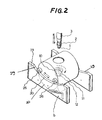
- a spherical surface machining apparatus for optical lenses, mirrors and so on, as shown in Fig. 2.
- This apparatus allows selection of a reference cam 29, chose from those having cam profiles with different spherical surfaces, in accordance with desired spherical surface machining.
- a spindle 12 of a grinding plate 10 can be moved in an axial direction and fixed so as to meet the requirement of the spherical surface machining, which permits free changing of the spherical center swinging trajectory of the spindle 12 of the grinding plate 10, whereby any lens materials 1 can be arbitrarily processed to form a desired spherical surface.
- the above-mentioned apparatus can be used for any use, more specifically, for forming convex, concave and flat surfaces and does not require a complicated procedure to set the spherical surface. Further, since this apparatus performs surface cutting, machining time can be reduced substantially and a highly accurate finished surface can be obtained compared with conventional apparatus. Further, this apparatus can be used for polishing lens material, in addition to grinding by changing the lens chucking method to a method providing freedom of movement for a lens attachment.
- the above-mentioned spherical surface machining apparatus though providing easy surface grinding while maintaining versatility and high accuracy, is constructed such that two reference cams 29, with cam profiles having highly accurate curved surfaces, are disposed on opposed sides of the grinding plate 10, and the two reference cams 29 must be positioned symmetrically with respect to the grinding plate 10.
- positioning is a quite time-consuming operation.
- swinging movement of the spindle 12 of the grinding plate 10 is performed by a swing apparatus b provided separately from a swing body 20. Therefore, this apparatus has a complicated construction and not only requires a long time for changing or adjusting the reference cams 29 but also is quite expensive and large.
- An object of the present invention is to improve the above described spherical surface machining apparatus provided by the present assignee in order to overcome or at least mitigate the problems mentioned above by providing a simply constructed spherical surface machining apparatus for optical lenses, mirrors and so on which is capable of easily performing surface cutting while maintaining high accuracy and versatility and providing a reduced sized apparatus with easy adjustability.
- a spherical surface machining apparatus for machining materials to be machined such as optical lenses and mirrors by rotating and swinging a lower shaft of a grinding plate and pressing the material to be machined on the spherical axis with respect to the grinding plate
- the machining apparatus comprising: an exchangeable referenee cam, mounted on one side of the grinding plate, having a curved or planar cam profile and a portion of a cam surface formed with a rack; and a swing body movably mounted on the cam surface of the reference cam through a driving cam follower meshing with the rack for axially movably supporting the lower shaft of the grinding plate, wherein the lower shaft of the grinding plate is axially moved and the driving cam follower is driven to thereby make free the spherical center swinging trajectory of the lower shaft of the grinding plate.
- a transporting apparatus for transporting machined materials such as optical lenses and mirrors comprising: supply means having containers for accommodating the materials to be machined and fixtures for fixing and releasing each of the containers at a predetermined position, the supply means arranged reciprocally movable between a grinding plate and a chuck; and transporting means, associated with the supply means, for receiving the containers from the supply means and transporting the containers.
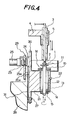
- lens material 1 or an object to be processed is firmly supported by a chuck 2 which is secured on the lower end of an upper shaft 3 pivotably arranged on an arm base 4 through an upper support 5. Since the upper shaft 3 is axially elevated by means of the arm base 4, the lens material 1 firmly supported by the chuck 2 is also axially elevatable.
- a grinding plate 10 On a grinding plate 10, diamond pellets 11 of, for example #300 are mounted at predetermined intervals.
- This grinding plate 10 is removably fixed on the upper end of a spindle (lower shaft) 12 which is pivoted on a lower support 13 through bearings 14.
- a pulley 15 On the lower end of the spindle 12, a pulley 15 is fixed, and a motor 17 is fixed on a bracket 16 protruding from a mounting 21 of a swing body 20.
- a pulley 18 On the driving shaft of the motor 17 a pulley 18 is fitted.
- Such a construction allows the spindle 12 to rotate at a high speed, for example, 3000 r.p.m., driven by the motor 17 through a belt wound around the pulleys 15, 18.
- the lower support 13, supported by the mounting 21 of the swing body 20, may be fixed at an arbitrary position on the mounting 21 in the axial direction by means of a setting bolt 22.
- a driving cam follower 23 having teeth 23a for serving as a pinion is rotatably mounted on a lateral surface 20a of the swing body 20.
- This driving cam follower 23 is forwardly and reversely rotatable by means of a motor or a drive unit 25 secured on a bracket 24 protruding from a lateral surface of the mounting 21 of the swing body 20.
- a swing cam follower 26 and a swing stop cam follower 27 are respectively mounted in a rotatable manner on a lateral surface 20a of the swing body 20.
- the swing body 20 is movably mounted on a rack 30a and non-racked surface 30b of a cam surface 30 of a reference cam 29 removably mounted on a body frame 28 through the driving cam follower and the swing cam follower 26. Further, the swing body 20 is equipped with the swing stop cam follower 27 movably mounted on a support plate 31 having a surface perpendicular to the cam surface of the reference cam 29 mounted on the body frame 28. Therefore, the driving, swing and swing stop cam followers 23, 26 and 27 allow the swing body 20 to swing on the cam surface 30 of the reference cam 29 without disengagement or vibration.
- the above-mentioned reference cam 29, which has the cam surface 30 composed of the rack 30a and the non-racked surface 30b, can provide a freely determinable profile, for example, convex, concave, flat and so on. If reference cams 29 having radii of curvature of integer multiples of, for example, 100 mm are provided and the movable range of the spindle 12 in the axial direction is limited to, for example, 50 mm from a reference position of the reference cam 29 in the upward and downward directions, the apparatus of the present embodiment can provide any spherical surface from the lens material 1 to be ground or polished.
- the abrasion of the diamond pellet 11 due to grinding of the lens material 1 is measured by a counter, and the position of the diamond pellet 11 is corrected by slightly elevating the spindle 12 by means of a ratchet actuated by an air cylinder or the like (these elements are not shown).
- the lens material 1 to be ground is mounted on the chuck 2, and a diamond pellet 11 which is assumed to provide the requisite and sufficient ground finished surface, for example, #300 is selected and mounted on the grinding plate 10.
- the radius (R) of the lens material 1 to be ground or polished has been determined, one of the reference cams 29 appropriate to this radius is selected.
- the radius R of the reference cam 29, for example, for a convex surface cam, as shown in Fig. 6, is determined such that the center of the distance between the center x of the driving cam follower 23 and the center y of the swing cam follower 26 is designated the origin O, with the distances xo , yo being represented by A.
- the center of the radius R of the reference cam 29 is designated P, the distance of PO B, and the diameter of the driving and swing cam followers 23, 26 C.
- R is determined by the above formula.
- the center of the distance between the center x of the driving cam follower 23 and the center y of the swing cam follower 26 is designated the origin O, with the distances xo , yo being represented by A.
- the center of the radius R of the reference cam 29 is designated P, the distance of PO B, and the diameter of the driving and swing cam followers 23, 36 C.
- convex surface and concave surface reference cams 29 having radii R of 100 mm, 200 mm, 300 mm, ..., that is, integer multiples of 100 mm if the radius R of the convex surface reference cam 29 is calculated to be 140 mm, by way of example, the reference cam 29 having the radius of 100 mm is selected. In another case, if the radius of the convex surface reference cam 29 is calculated to be 70 mm by the formula (1), the reference cam 29 having the radius of 100 mm is selected.
- the concave surface reference cam 29 is selected in a similar manner to the convex surface reference cam 29 by the formula (2).
- the spindle 12 is moved within a range of 50 mm in the upward and downward direction based on the origin O in accordance with R of the lens material 1 to be ground or polished and fixed at an appropriate position on the swing body 20 by means of the lower support 13.
- the spindle 12 is rotated at a high speed by the motor 17, and the driving cam follower 23 is forwardly and reversely rotated by the motor 25, whereby the swing body 20 swings on the rack 30a of the reference cam 29, which results in that the spindle 12 exhibiting a freely changing spherical center swinging trajectory through the swing body 20.
- the lens material 1 can be ground or polished to form a spherical surface.
- one of the reference cams is selected and mounted on one side of the grinding plate.
- the lower shaft of the grinding plate is positioned according to the objective of the spherical surface machining, and the driving cam follower is driven, whereby the spherical center swinging trajectory of the lower shaft of the grinding plate becomes free through the swing body, therefore making it possible to freely machine optical lenses, mirrors and so on to form desired spherical surfaces.
- a single apparatus can be used for forming any desired spherical surface such as a convex surface, a concave surface, a flat surface and so on.
- the handling necessary for setting a spherical surface is quite easy.
- the surface cut performed by the apparatus of the present embodiment can provide a largely reduced machining time and highly accurate finished surfaces.
- the apparatus can be used also as a polishing machine by changing the lens chucking method to provide a method providing freedom to the lens attachment.
- the swing body is inseparably supported on the reference cam by means of the driving, swing and support cam followers, the spherical center swinging trajectory of the lower shaft of the grinding plate is free of vibration even with a single reference cam.
- the spherical center swinging trajectory of the lower shaft of the grinding plate can be obtained through the swing body by driving the driving unit equipped with the swing body to rotate the driving cam follower so that the construction of the driving unit for providing swinging movement is simple and the size of the overall apparatus can be reduced.
- a container 40, provided for accommodating the lens material 1, is transported by a supply belt conveyer (supplier) 41.
- the supply belt conveyer 41 is operable by rotating a roller 42 by means of a motor (not shown).
- the supply belt conveyer 41 has fixing means 43, 44, (see Fig. 8(1)) with which the container 40 can be fixed on the supply belt conveyer 41.
- the supply belt conveyer 41 itself is reciprocally movable in a transporting direction towards and away from the grinding plate 10. This reciprocal movement is performed such that the axis of the chuck 2 is positioned on the axial center of the lens material 1 in the containers 40 fixed on the supply belt conveyer 41 by the fixing means 43, 44.
- the containers 40 accommodating machined lens material 1 are transported to a predetermined position by a transporting belt conveyer (carrier) 45.
- Fig. 8 shows the first step of a method of transporting optical lenses, mirrors and so on, wherein a predetermined number of containers 40, for example, three containers 401, 402, 403 are provided for accommodating lens material 11, 12, 13 to be ground, and the containers 401, 402 are carried on the supply belt conveyer 41.
- a predetermined number of containers 40 for example, three containers 401, 402, 403 are provided for accommodating lens material 11, 12, 13 to be ground, and the containers 401, 402 are carried on the supply belt conveyer 41.
- Fig. 9 shows the second step of the transportation method, wherein a roller 42 is rotated to run the supply belt conveyer 41 for transporting the containers 401, 402 to the positions of fixing means 43, 44 where the containers 40 1 , 402 are fixed by the fixing means 43, 44, respectively.
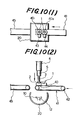
- Fig. 10 shows the third step, wherein the supply belt conveyer 41 itself is moved toward a first position in the lefthand direction of the drawing.
- This first position is a position where the axis of the chuck 2 substantially passes through the axial center of the lens material 11 accommodated in the container 401.
- Fig. 11 shows the fourth step wherein the chuck 2 is lowered by lowering the upper shaft 3 to firmly hold the lens material 11 on the chuck 2 and then elevated by elevating the upper shaft 3.
- the supply belt conveyer 41 is then moved in the righthand direction of Fig. 11, the arm base 4 is lowered and the grinding of the lens material 11 is started.
- Fig. 12 shows the fifth step.
- the arm base 4 is elevated, and the belt conveyer 41 is moved in the lefthand direction to the first position.
- the upper shaft 3 is lowered to lower the chuck 2 to reaccommodate the lens material 11 in the container 401.
- Fig. 13 shows the sixth step.
- the supply belt conveyer 41 is moved in the lefthand direction of the drawing to a second position. This second position is a position where the axis of the chuck 2 passes the axial center of the lens material 12 accommodated in the container 402. Then, the container 401 is released from its fixed condition and the container 403 which contains lens material 13 to be ground is fed onto the supply belt conveyer 41.
- Fig. 14 shows the seventh step, where the supply belt conveyer 41 and the transporting belt conveyer 45 are adjacent.
- the container 401 is transferred onto the transporting belt conveyer 45 to be carried to a predetermined place.
- the lens material 12 in the container 402 fixed by the fixture 44 is firmly held by the chuck 2 which is then elevated with the lens material 12.
- the containers 402, 403 are transported to the positions of the fixing means 43, 44, with which the containers 402, 403 are fixed.
- the belt conveyer 41 is next moved in the righthand direction of Fig. 14, and the arm base 4 is lowered to return to the fourth step, where the grinding of the lens material 12 is started (see Fig. 11).
- a lens to be ground and accommodated in a container is transported by a supply means to the position of the axis of a grinding holder, received by the grinding holder, and a vacant container is transported to the position of the axis of the grinding holder by the supply means to receive the ground lens.
- the container with the ground lens is transferred from the supply means to a transport means which transports the container to a predetermined place.
- lenses to be ground can be directly transported to the grinding holder by the supply means and then ground lenses transported directly to the outside by the transport means, thereby rendering it possible to reduce the loading time.
Landscapes
- Engineering & Computer Science (AREA)
- Mechanical Engineering (AREA)
- Automation & Control Theory (AREA)
- Grinding And Polishing Of Tertiary Curved Surfaces And Surfaces With Complex Shapes (AREA)
Applications Claiming Priority (2)
| Application Number | Priority Date | Filing Date | Title |
|---|---|---|---|
| JP49842/90 | 1990-03-01 | ||
| JP2049842A JPH0761606B2 (ja) | 1990-03-01 | 1990-03-01 | 光学レンズ・ミラー等球面加工装置 |
Publications (3)
| Publication Number | Publication Date |
|---|---|
| EP0445988A2 true EP0445988A2 (de) | 1991-09-11 |
| EP0445988A3 EP0445988A3 (en) | 1992-02-05 |
| EP0445988B1 EP0445988B1 (de) | 1994-12-07 |
Family
ID=12842329
Family Applications (1)
| Application Number | Title | Priority Date | Filing Date |
|---|---|---|---|
| EP91301726A Expired - Lifetime EP0445988B1 (de) | 1990-03-01 | 1991-03-01 | Gerät zum Bearbeiten von sphärischen Flächen und dazugehörige Fördereinrichtung |
Country Status (4)
| Country | Link |
|---|---|
| US (1) | US5154020A (de) |
| EP (1) | EP0445988B1 (de) |
| JP (1) | JPH0761606B2 (de) |
| DE (1) | DE69105557T2 (de) |
Cited By (1)
| Publication number | Priority date | Publication date | Assignee | Title |
|---|---|---|---|---|
| WO1999052673A1 (de) * | 1998-04-08 | 1999-10-21 | Wernicke & Co. Gmbh | Anlage zum formbearbeiten der ränder von brillengläsern |
Families Citing this family (4)
| Publication number | Priority date | Publication date | Assignee | Title |
|---|---|---|---|---|
| US5411430A (en) * | 1991-09-25 | 1995-05-02 | Hitachi Ltd. | Scanning optical device and method for making a hybrid scanning lens used therefor |
| AU2001237285A1 (en) * | 2000-02-03 | 2001-08-14 | Carl Zeiss | Polishing head for a polishing machine |
| JP4727809B2 (ja) * | 2000-12-14 | 2011-07-20 | 株式会社トプコン | シリンダー面の研磨装置及びその研磨方法 |
| CN121104829B (zh) * | 2025-11-07 | 2026-02-06 | 四川科特检测技术有限公司 | 一种旋塞阀阀座内球面精度加工工艺及其加工装置 |
Family Cites Families (11)
| Publication number | Priority date | Publication date | Assignee | Title |
|---|---|---|---|---|
| US1343522A (en) * | 1916-04-15 | 1920-06-15 | Universal Grinding Machine Com | Process for grinding and polishing lenses |
| FR1233568A (fr) * | 1959-04-07 | 1960-10-12 | Comm Ouvriers Lunetiers Soc In | Machine à doucir |
| DE1577373B1 (de) * | 1967-01-17 | 1970-06-25 | Hertel Karl | Einrichtung zum massgenauen Anschleifen des variabel einstellbaren Spitzenradius eines im Schwenkarm einer Kopier-Stirnschleifmaschine eingespannten Drehmeissels |
| US3835596A (en) * | 1972-08-10 | 1974-09-17 | Bausch & Lomb | Apparatus for and method of removing material from a flexible contact lens |
| DE2721553C3 (de) * | 1977-05-13 | 1980-11-13 | Prontor-Werk Alfred Gauthier Gmbh, 7547 Wildbad | Maschine zum Schleifen und Polieren von Werkstücken mit sphärischer Oberfläche, insbesondere von Linsen |
| DE3143846C2 (de) * | 1981-11-05 | 1983-11-03 | Messerschmitt-Bölkow-Blohm GmbH, 8000 München | Verwundenes Profil-Bauteil und Vorrichtung zur Bearbeitung von Polygonzug-Flächen |
| FR2565147B1 (fr) * | 1984-06-04 | 1988-04-01 | Essilor Int | Machine a meuler pour lentille ophtalmique, notamment pour le detourage et/ou le biseautage ou rainurage de celle-ci |
| US4662119A (en) * | 1984-07-25 | 1987-05-05 | Haruchika Precision Company, Ltd. | Automatic lens grinding apparatus |
| JPS6299065A (ja) * | 1985-10-22 | 1987-05-08 | Matsushita Electric Ind Co Ltd | 球面研削装置 |
| IT1209106B (it) * | 1985-11-05 | 1989-07-10 | Ivano Paolini | Macchina automatica per sagomare il profilo esterno di lenti per occhiali |
| FR2636555B1 (fr) * | 1988-09-22 | 1994-07-29 | Essilor Int | Restituteur de gabarit pour machine a meuler, en particulier pour verres de lunettes |
-
1990
- 1990-03-01 JP JP2049842A patent/JPH0761606B2/ja not_active Expired - Fee Related
-
1991
- 1991-02-26 US US07/661,708 patent/US5154020A/en not_active Expired - Lifetime
- 1991-03-01 DE DE69105557T patent/DE69105557T2/de not_active Expired - Fee Related
- 1991-03-01 EP EP91301726A patent/EP0445988B1/de not_active Expired - Lifetime
Cited By (1)
| Publication number | Priority date | Publication date | Assignee | Title |
|---|---|---|---|---|
| WO1999052673A1 (de) * | 1998-04-08 | 1999-10-21 | Wernicke & Co. Gmbh | Anlage zum formbearbeiten der ränder von brillengläsern |
Also Published As
| Publication number | Publication date |
|---|---|
| JPH0761606B2 (ja) | 1995-07-05 |
| US5154020A (en) | 1992-10-13 |
| EP0445988B1 (de) | 1994-12-07 |
| EP0445988A3 (en) | 1992-02-05 |
| DE69105557T2 (de) | 1995-07-13 |
| DE69105557D1 (de) | 1995-01-19 |
| JPH03251354A (ja) | 1991-11-08 |
Similar Documents
| Publication | Publication Date | Title |
|---|---|---|
| US5053971A (en) | Method and apparatus for edging an optical lens | |
| US4928435A (en) | Apparatus for working curved surfaces on a workpiece | |
| US4829716A (en) | Apparatus for automatically performing plural sequential spherical grinding operations on workpieces | |
| US6419443B2 (en) | Glass product machining apparatus | |
| US3117396A (en) | Lens grinding apparatus and method | |
| US5018313A (en) | Roundness processing device of a slipper surface of a rocker arm | |
| US4038783A (en) | Method and apparatus for generating optic lenses | |
| JP2006312234A (ja) | 高性能フライス削り・旋削装置および特に眼鏡レンズを加工する方法 | |
| EP1415762B1 (de) | Vorrichtung und Verfahren zur Bearbeitung des Endes von optischen Verbindern | |
| EP0445988B1 (de) | Gerät zum Bearbeiten von sphärischen Flächen und dazugehörige Fördereinrichtung | |
| CA1150951A (en) | Ring gear burnishing machine | |
| JPS597550A (ja) | 曲面研削加工機械 | |
| CN218504205U (zh) | 一种精密球面研磨抛光机 | |
| JPH1148107A (ja) | 両面研削方法およびその装置 | |
| JP2957224B2 (ja) | 玉摺機の面取機構 | |
| EP0754524B1 (de) | Gerät zum Abrichten eines Linsenschleifsteines | |
| GB2058619A (en) | Lens surface generating apparatus | |
| EP0128779B1 (de) | Schleifeinrichtung für sphärische Flächen | |
| CN219853598U (zh) | 一种轴承内圈表面整形设备 | |
| CN220699152U (zh) | 斜面式磨抛机 | |
| JPH0929599A (ja) | 球面加工方法及びその装置 | |
| JPH03294163A (ja) | 曲面加工装置 | |
| JPH0430961A (ja) | トーリック形状および非球面形状レンズの加工装置及び加工方法 | |
| JP2003062743A (ja) | フェルールの球面研削装置及び球面研削方法 | |
| JP2001113454A (ja) | 球面、非球面の研磨方法と装置 |
Legal Events
| Date | Code | Title | Description |
|---|---|---|---|
| PUAI | Public reference made under article 153(3) epc to a published international application that has entered the european phase |
Free format text: ORIGINAL CODE: 0009012 |
|
| AK | Designated contracting states |
Kind code of ref document: A2 Designated state(s): DE FR GB IT |
|
| PUAL | Search report despatched |
Free format text: ORIGINAL CODE: 0009013 |
|
| AK | Designated contracting states |
Kind code of ref document: A3 Designated state(s): DE FR GB IT |
|
| 17P | Request for examination filed |
Effective date: 19920204 |
|
| 17Q | First examination report despatched |
Effective date: 19930405 |
|
| GRAA | (expected) grant |
Free format text: ORIGINAL CODE: 0009210 |
|
| AK | Designated contracting states |
Kind code of ref document: B1 Designated state(s): DE FR GB IT |
|
| REF | Corresponds to: |
Ref document number: 69105557 Country of ref document: DE Date of ref document: 19950119 |
|
| ET | Fr: translation filed | ||
| ITF | It: translation for a ep patent filed | ||
| PLBE | No opposition filed within time limit |
Free format text: ORIGINAL CODE: 0009261 |
|
| STAA | Information on the status of an ep patent application or granted ep patent |
Free format text: STATUS: NO OPPOSITION FILED WITHIN TIME LIMIT |
|
| 26N | No opposition filed | ||
| REG | Reference to a national code |
Ref country code: GB Ref legal event code: IF02 |
|
| PGFP | Annual fee paid to national office [announced via postgrant information from national office to epo] |
Ref country code: IT Payment date: 20080319 Year of fee payment: 18 Ref country code: GB Payment date: 20080220 Year of fee payment: 18 |
|
| PGFP | Annual fee paid to national office [announced via postgrant information from national office to epo] |
Ref country code: FR Payment date: 20080312 Year of fee payment: 18 Ref country code: DE Payment date: 20080327 Year of fee payment: 18 |
|
| GBPC | Gb: european patent ceased through non-payment of renewal fee |
Effective date: 20090301 |
|
| REG | Reference to a national code |
Ref country code: FR Ref legal event code: ST Effective date: 20091130 |
|
| PG25 | Lapsed in a contracting state [announced via postgrant information from national office to epo] |
Ref country code: DE Free format text: LAPSE BECAUSE OF NON-PAYMENT OF DUE FEES Effective date: 20091001 |
|
| PG25 | Lapsed in a contracting state [announced via postgrant information from national office to epo] |
Ref country code: GB Free format text: LAPSE BECAUSE OF NON-PAYMENT OF DUE FEES Effective date: 20090301 Ref country code: FR Free format text: LAPSE BECAUSE OF NON-PAYMENT OF DUE FEES Effective date: 20091123 |
|
| PG25 | Lapsed in a contracting state [announced via postgrant information from national office to epo] |
Ref country code: IT Free format text: LAPSE BECAUSE OF NON-PAYMENT OF DUE FEES Effective date: 20090301 |