EP0446119B1 - Herstellungsverfahren eines Lüfterrades für rotierende elektrische Maschinen, insbesondere für Wechselstromgeneratoren für Kraftfahrzeuge und Lüfterrad durch ein solches Verfahren hergestellt - Google Patents
Herstellungsverfahren eines Lüfterrades für rotierende elektrische Maschinen, insbesondere für Wechselstromgeneratoren für Kraftfahrzeuge und Lüfterrad durch ein solches Verfahren hergestellt Download PDFInfo
- Publication number
- EP0446119B1 EP0446119B1 EP91400589A EP91400589A EP0446119B1 EP 0446119 B1 EP0446119 B1 EP 0446119B1 EP 91400589 A EP91400589 A EP 91400589A EP 91400589 A EP91400589 A EP 91400589A EP 0446119 B1 EP0446119 B1 EP 0446119B1
- Authority
- EP
- European Patent Office
- Prior art keywords
- fan rotor
- fan
- manufacture according
- metal strip
- fan blades
- Prior art date
- Legal status (The legal status is an assumption and is not a legal conclusion. Google has not performed a legal analysis and makes no representation as to the accuracy of the status listed.)
- Expired - Lifetime
Links
- 238000000034 method Methods 0.000 title claims description 17
- 238000004519 manufacturing process Methods 0.000 title claims description 15
- 239000002184 metal Substances 0.000 claims description 20
- 238000005452 bending Methods 0.000 claims 4
- 238000003825 pressing Methods 0.000 claims 3
- 238000009423 ventilation Methods 0.000 description 23
- 241000940835 Pales Species 0.000 description 3
- 206010033546 Pallor Diseases 0.000 description 3
- 238000004140 cleaning Methods 0.000 description 2
- 238000001816 cooling Methods 0.000 description 2
- 230000001788 irregular Effects 0.000 description 2
- 229920000297 Rayon Polymers 0.000 description 1
- 240000008042 Zea mays Species 0.000 description 1
- 238000005520 cutting process Methods 0.000 description 1
- 230000002093 peripheral effect Effects 0.000 description 1
- 239000002964 rayon Substances 0.000 description 1
- 238000003466 welding Methods 0.000 description 1
Images

Classifications
-
- F—MECHANICAL ENGINEERING; LIGHTING; HEATING; WEAPONS; BLASTING
- F04—POSITIVE - DISPLACEMENT MACHINES FOR LIQUIDS; PUMPS FOR LIQUIDS OR ELASTIC FLUIDS
- F04D—NON-POSITIVE-DISPLACEMENT PUMPS
- F04D29/00—Details, component parts, or accessories
- F04D29/26—Rotors specially for elastic fluids
- F04D29/28—Rotors specially for elastic fluids for centrifugal or helico-centrifugal pumps for radial-flow or helico-centrifugal pumps
- F04D29/281—Rotors specially for elastic fluids for centrifugal or helico-centrifugal pumps for radial-flow or helico-centrifugal pumps for fans or blowers
-
- B—PERFORMING OPERATIONS; TRANSPORTING
- B21—MECHANICAL METAL-WORKING WITHOUT ESSENTIALLY REMOVING MATERIAL; PUNCHING METAL
- B21D—WORKING OR PROCESSING OF SHEET METAL OR METAL TUBES, RODS OR PROFILES WITHOUT ESSENTIALLY REMOVING MATERIAL; PUNCHING METAL
- B21D53/00—Making other particular articles
- B21D53/26—Making other particular articles wheels or the like
- B21D53/267—Making other particular articles wheels or the like blower wheels, i.e. wheels provided with fan elements
-
- Y—GENERAL TAGGING OF NEW TECHNOLOGICAL DEVELOPMENTS; GENERAL TAGGING OF CROSS-SECTIONAL TECHNOLOGIES SPANNING OVER SEVERAL SECTIONS OF THE IPC; TECHNICAL SUBJECTS COVERED BY FORMER USPC CROSS-REFERENCE ART COLLECTIONS [XRACs] AND DIGESTS
- Y10—TECHNICAL SUBJECTS COVERED BY FORMER USPC
- Y10T—TECHNICAL SUBJECTS COVERED BY FORMER US CLASSIFICATION
- Y10T29/00—Metal working
- Y10T29/49—Method of mechanical manufacture
- Y10T29/49316—Impeller making
- Y10T29/4932—Turbomachine making
- Y10T29/49325—Shaping integrally bladed rotor
-
- Y—GENERAL TAGGING OF NEW TECHNOLOGICAL DEVELOPMENTS; GENERAL TAGGING OF CROSS-SECTIONAL TECHNOLOGIES SPANNING OVER SEVERAL SECTIONS OF THE IPC; TECHNICAL SUBJECTS COVERED BY FORMER USPC CROSS-REFERENCE ART COLLECTIONS [XRACs] AND DIGESTS
- Y10—TECHNICAL SUBJECTS COVERED BY FORMER USPC
- Y10T—TECHNICAL SUBJECTS COVERED BY FORMER US CLASSIFICATION
- Y10T29/00—Metal working
- Y10T29/49—Method of mechanical manufacture
- Y10T29/49316—Impeller making
- Y10T29/49329—Centrifugal blower or fan
Definitions
- the present invention relates to a method of manufacturing a fan wheel for rotating electrical machines, in particular for alternators of motor vehicles, and a fan wheel obtained by such a method.
- Such devices need to be cooled during operation so as to remain at a limited temperature allowing them to ensure optimum performance.
- This cooling is generally obtained by forced ventilation through the device to be cooled by means of a fan wheel.
- the teeth are bent perpendicular to the sheet blank, in order to obtain ventilation blades.
- the number of ventilation blades that can be obtained depends on the peripheral circular surface of the sheet metal blank and, if, in rotating machines of large diameter, their number may be sufficient, this is not the case. similarly in rotating machines of small diameter such as for example motor vehicle alternators. For the same reasons, the area of the ventilation blades is also limited.
- quadrangular surfaces intended to be folded according to their midline are trapezoids.
- the surface of the ventilation blades can be increased since it only depends on the unit size of the folded surfaces.
- a fan wheel produced according to the above method has cooling performance perfectly suited to electric rotating machines such as alternators for the motor vehicle on which it is to be installed, and at a very reduced cost.
- the method according to the invention makes it possible to obtain non-radial and non-equidistant blades, which allows noise phenomena to be controlled in a particularly economical manner.
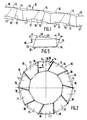
- the fan wheel is obtained from a metal strip 10 partially shown in Figure 1, the shape (shown in phantom) is rectangular.
- this metal strip 10 is divided into 2n quadrangular surfaces, n being the number of blades to be fitted with the fan wheel.
- quadrangular surfaces 11 On the metal strip are alternated quadrangular surfaces 11 having outer edges 16,17, and quadrangular surfaces 12, said quadrangular surfaces 12 preferably having a generally trapezoidal shape.
- These surfaces 12 each have a center line 13 perpendicular to the outer edges 14,15 which are parallel to each other.
- said center line 13 generally constitutes the bisector of the angle formed by the lateral sides of said surface 12.
- the trapezoidal surfaces 12 are folded successively or simultaneously along their median lines 13 to form the ventilation blades 18 of the fan wheel 19.
- the quadrangular surfaces 11 constitute connecting surfaces between two successive vertilation blades 18.
- a fan wheel 19 is thus produced from a metal strip 10, the outline of which has the shape of an irregular polygon of n sides as shown in FIG. 2.
- the ventilation blades 18 thus formed are neither radial nor equidistant, which allows the fan wheel 19 to have increased efficiency while reducing, or even eliminating noise phenomena.
- the size of the blades can be increased since it only depends on the size unit of the trapezoidal surfaces 12. Likewise, their number is no longer limited since it only depends on the unit size of the quadrangular surfaces 11.
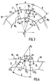
- Figure 3 is a partial view of the fan wheel 19 produced according to the invention.
- the outer contour 20 of said wheel is in the form of an irregular polygon whose vertices S1, S2, S3 .... are inscribed in a circle 21 with center O.
- the blades 181, 182, 183 .... have variable inclinations ⁇ 1, ⁇ 2, ⁇ 3 .... compared to the radii OS1, OS2, OS3 ....
- variable angles A, B correspond to the angular differences respectively between the vertices S1, S2 on the one hand, S2, S3 on the other hand.
- FIG. 4 where a partial view of the metal strip 10 before folding has been shown corresponding to the blade 182 of FIG. 3.
- the sides 222 of the trapezoid formed by the surface 122 have, with respect to the edges 16, angles C + D previously calculated.
- E 180 ° - (C + D)
- E 180 ° - (90 ° - A / 2 - ⁇ 2 + 90 ° - B / 2 + ⁇ 2).
- angle F 90 ° + (A + B) / 4.
- the median line 132 constitutes the bisector of the angle E formed by the sides 222 of the surface 122.
- FIG. 5 illustrates a profile view of a ventilation blade 18 obtained with the manufacturing method according to the invention.
- This ventilation blade has an upper face 23 making an angle P with the horizontal, that is to say an angle P with respect to the base 10 of the fan wheel 10.
- Said ventilation blade 18 also has an outer side 24 making an angle R with the vertical that is to say with a perpendicular to the base 10 of the fan wheel 19.
- This V-shaped notch 25 has sides 26 symmetrical with respect to the center line 13 and which are perpendicular to the sides 22 of the trapezoidal surface 12 at the points of intersection 27,28 of said sides 22 and of the outer edge 14 of the trapezoidal surface 12 .
- V-shaped notch 30 (FIG. 6) which opens out towards the outer edge 15 of the trapezoidal surface 12 and is symmetrical with respect to the center line 13.
- V-shaped notches 25, 30 are made on all the trapezoidal surfaces so that all the ventilation blades are identical.
- the metal strip 10 is cut straight along widths L1, L2, L3 as shown in FIG. 7.
- FIG. 8 schematically represents a fan wheel 19 obtained with a straight cutout of the metal strip 10. It can be seen in particular that the external and internal contours of the polygon formed by the edges 16, 17 of the quadrangular surfaces 11 have notches at the right ventilation blades 18.
Landscapes
- Engineering & Computer Science (AREA)
- Mechanical Engineering (AREA)
- General Engineering & Computer Science (AREA)
- Structures Of Non-Positive Displacement Pumps (AREA)
- Motor Or Generator Cooling System (AREA)
- Manufacture Of Motors, Generators (AREA)
Claims (8)
- Herstellungsverfahren eines Lufterrades (19), insbesondere für rotierende elektrische Maschinen, wobei dieses Lüfterrad n Lüfterflügel (18) umfassen soll, bestehend aus den folgenden Arbeitsgängen:- es wird ein Metallband (10) mit länglicher Form gebildet;- das besagte Metallband (10) wird in 2n Flächen (11, 12) mit allgemein viereckiger Form geteilt;- nacheinander oder gleichzeitig wird jede zweite viereckige Fläche (12) im Verhältnis zu ihrer Mittellinie (13), die durch die Winkelhalbierende des aus den beiden Seiten (22) der besagten viereckigen Fläche (12) bestehenden Winkels (E) gebildet wird, so gebogen, daß das Lüfterrad (19) nach dem Biegen einen Umriß (20) in Form eines Vielecks mit Scheiteln (S1, S2, S3 ...) aufweist, die in einen Kreis (21) mit dem Mittelpunkt (O) eingeschrieben sind, wobei die Lüfterflügel (18) eine veränderliche Neigung (α1, α2, α3 ...) im Verhältnis zu den Radien (OS1, OS2, OS3 ...) aufweisen.
- Herstellungsverfahren nach Anspruch 1, dadurch gekennzeichnet, daß die Scheitel (S1, S2, S3 ...) und folglich die Lüfterflügel (18) einen veränderlichen Winkelabstand (A, B ...) aufweisen.
- Herstellungsverfahren nach einem der vorangehenden Ansprüche, dadurch gekennzeichnet, daß vor jedem Vorgang zum Biegen der Flächen (12) durch Einschneiden jeder dieser Flächen ein V-förmiger Einschnitt (25) angebracht wird, der Seiten (26) aufweist, die senkrecht zu den Seiten (22) der Fläche (12) in den Schnittpunkten (27, 28) der besagten Seiten (22) mit der Außenkante (14) verlaufen.
- Herstellungsverfahren nach einem der vorangehenden Ansprüche, dadurch gekennzeichnet, daß vor jedem Vorgang zum Biegen der Flächen (12) durch Einschneiden jeder dieser Flächen ein V-förmiger Einschnitt (30) angebracht wird, der symmetrisch im Verhältnis zur Mittellinie (13) angeordnet ist und gegenüber der Kante (15) mündet.
- Herstellungsverfahren nach einem der vorangehenden Ansprüche, dadurch gekennzeichnet, daß vor jedem Biegevorgang ein gerades Schneiden des Metallbands (10) erfolgt.
- Herstellungsverfahren nach Anspruch 5, dadurch gekennzeichnet, daß nach dem Biegen die Außen- und Innenumrisse des Vielecks, die durch die Kanten (16, 17) der viereckigen Flächen (11) gebildet werden, Absätze in Höhe der Lüfterflügel (18) aufweisen.
- Herstellungsverfahren nach Anspruch 5, dadurch gekennzeichnet, daß die Lüfterflügel (18) Flächen (31, 32) aufweisen, die sich teilweise überdecken.
- Lüfterrad (19) mit n Lüfterflügeln (18) , dadurch gekennzeichnet, daß das besagte Lüfterrad (19) durch das Verfahren nach einem der Ansprüche 1 bis 7 hergestellt wird.
Applications Claiming Priority (2)
| Application Number | Priority Date | Filing Date | Title |
|---|---|---|---|
| FR9002926 | 1990-03-08 | ||
| FR9002926A FR2659506B1 (fr) | 1990-03-08 | 1990-03-08 | Procede de fabrication d'une roue de ventilateur pour machines tournantes electriques, notamment pour alternateurs de vehicules automobiles, et roue de ventilateur obtenue par un tel procede. |
Publications (2)
| Publication Number | Publication Date |
|---|---|
| EP0446119A1 EP0446119A1 (de) | 1991-09-11 |
| EP0446119B1 true EP0446119B1 (de) | 1995-08-02 |
Family
ID=9394506
Family Applications (1)
| Application Number | Title | Priority Date | Filing Date |
|---|---|---|---|
| EP91400589A Expired - Lifetime EP0446119B1 (de) | 1990-03-08 | 1991-03-05 | Herstellungsverfahren eines Lüfterrades für rotierende elektrische Maschinen, insbesondere für Wechselstromgeneratoren für Kraftfahrzeuge und Lüfterrad durch ein solches Verfahren hergestellt |
Country Status (6)
| Country | Link |
|---|---|
| US (1) | US5075964A (de) |
| EP (1) | EP0446119B1 (de) |
| JP (1) | JPH05332295A (de) |
| DE (1) | DE69111641T2 (de) |
| ES (1) | ES2079594T3 (de) |
| FR (1) | FR2659506B1 (de) |
Families Citing this family (8)
| Publication number | Priority date | Publication date | Assignee | Title |
|---|---|---|---|---|
| DE19545977A1 (de) * | 1995-12-09 | 1997-06-12 | Fluck Hans Joachim Dr Dipl Ing | Lauf- bzw. Lüfterrad für Strömungsmaschinen und Verfahren zu seiner Herstellung |
| US6948910B2 (en) | 2002-07-12 | 2005-09-27 | Polacsek Ronald R | Spiral-based axial flow devices |
| US8251662B2 (en) | 2007-01-22 | 2012-08-28 | Parker Daniel B | Wind turbine blade assembly and apparatus |
| US8881396B2 (en) | 2011-02-07 | 2014-11-11 | Revcor, Inc. | Method of manufacturing a fan assembly |
| FR3021171B1 (fr) * | 2014-05-14 | 2020-09-04 | Valeo Equip Electr Moteur | Ventilateur de machine electrique tournante |
| US10865808B2 (en) * | 2014-05-14 | 2020-12-15 | Valeo Equipements Electriques Moteur | Fan for rotary electrical machine |
| JP2018121431A (ja) * | 2017-01-25 | 2018-08-02 | 株式会社デンソー | 回転電機の回転子及び回転電機 |
| US11274677B2 (en) | 2018-10-25 | 2022-03-15 | Revcor, Inc. | Blower assembly |
Citations (1)
| Publication number | Priority date | Publication date | Assignee | Title |
|---|---|---|---|---|
| GB541910A (en) * | 1939-05-20 | 1941-12-17 | Philco Radio & Television Corp | Cathode ray tube envelope |
Family Cites Families (8)
| Publication number | Priority date | Publication date | Assignee | Title |
|---|---|---|---|---|
| US1897947A (en) * | 1928-11-10 | 1933-02-14 | Bell & Howell Co | Fan structure |
| US2690151A (en) * | 1952-03-26 | 1954-09-28 | House William Carl | Means and method of making airfoils |
| US2802620A (en) * | 1953-02-16 | 1957-08-13 | Gen Motors Corp | Impeller for a centrifugal fan or blower |
| DE1958482A1 (de) * | 1969-11-21 | 1971-05-27 | Volkswagenwerk Ag | Luefterblech,insbesondere fuer Kraftfahrzeug-Aggregate |
| US3737966A (en) * | 1971-01-13 | 1973-06-12 | Lau Inc | Method of constructing a bladed blower wheel |
| US3921272A (en) * | 1974-05-24 | 1975-11-25 | Torin Corp | Blower wheel and method of making the same |
| US4329118A (en) * | 1980-01-08 | 1982-05-11 | Philips Industries, Inc. | Centrifugal blower wheels |
| US4741194A (en) * | 1986-09-25 | 1988-05-03 | The Budd Company | Composite rotor manufacturing method |
-
1990
- 1990-03-08 FR FR9002926A patent/FR2659506B1/fr not_active Expired - Fee Related
-
1991
- 1991-03-05 ES ES91400589T patent/ES2079594T3/es not_active Expired - Lifetime
- 1991-03-05 DE DE69111641T patent/DE69111641T2/de not_active Expired - Fee Related
- 1991-03-05 EP EP91400589A patent/EP0446119B1/de not_active Expired - Lifetime
- 1991-03-07 US US07/665,668 patent/US5075964A/en not_active Expired - Lifetime
- 1991-03-08 JP JP3067531A patent/JPH05332295A/ja active Pending
Patent Citations (1)
| Publication number | Priority date | Publication date | Assignee | Title |
|---|---|---|---|---|
| GB541910A (en) * | 1939-05-20 | 1941-12-17 | Philco Radio & Television Corp | Cathode ray tube envelope |
Also Published As
| Publication number | Publication date |
|---|---|
| DE69111641T2 (de) | 1996-01-25 |
| ES2079594T3 (es) | 1996-01-16 |
| EP0446119A1 (de) | 1991-09-11 |
| JPH05332295A (ja) | 1993-12-14 |
| US5075964A (en) | 1991-12-31 |
| FR2659506B1 (fr) | 1995-06-02 |
| DE69111641D1 (de) | 1995-09-07 |
| FR2659506A1 (fr) | 1991-09-13 |
Similar Documents
| Publication | Publication Date | Title |
|---|---|---|
| JP3989924B2 (ja) | ブレード根部保持スロットの機械加工方法 | |
| CA2396216C (fr) | Procede de fabrication d'un disque aubage monobloc de rotor et disque correspondant | |
| EP2925542B1 (de) | Winterreifenlaufstreifen mit einschnitten und hohlräumen | |
| EP2788205B1 (de) | Laufstreinfen profil mit variablen fasen | |
| EP0687582B1 (de) | Reifenlauffläche | |
| EP0446119A1 (de) | Herstellungsverfahren eines Lüfterrades für rotierende elektrische Maschinen, insbesondere für Wechselstromgeneratoren für Kraftfahrzeuge und Lüfterrad durch ein solches Verfahren hergestellt | |
| EP1414653A1 (de) | Mit schlitzen versehene lauffläche | |
| EP2552715B1 (de) | Reifenprofil mit einschnitten | |
| FR2711679A1 (fr) | ÓOEillet de fil pour lisse de tissage et lisse pourvue d'un tel Óoeillet ainsi que son procédé de réalisation. | |
| FR2513823A1 (fr) | Piece semi-finie de collecteur | |
| EP1051791B1 (de) | Herstellungsverfahren für einen Wechselstromgenerator für Kraftfahrzeuge mit Zwischenpolmagneten sowie nach diesem Verfahren hergestellter Generator | |
| FR2800015A1 (fr) | Pneumatique a capacite d'evacuation d'eau amelioree | |
| EP2509804B1 (de) | Verfahren für den entwurf eines reifens und reifen | |
| WO2012175893A1 (fr) | Pneumatique muni de canaux sonores | |
| EP0968848B1 (de) | Reifenlauffläche mit Einschnitten ,welche Gummiblöcke begrenzen | |
| WO2001032448A1 (fr) | Sculpture de bande de roulement pour pneumatique de vehicule a forte capacite de charge | |
| EP0500442B1 (de) | Lüfterrad für rotierende elektrische Maschinen, insbesondere für Wechselstromgeneratoren für Kraftfahrzeuge | |
| FR2652618A1 (fr) | Procede de fabrication d'une roue de ventilateur pour machines tournantes electriques, notamment pour alternateurs de vehicules automobiles, et roue de ventilateur obtenue par un tel procede. | |
| WO2002038303A1 (fr) | Procede de fabrication d'une jante de roue de vehicule | |
| FR2821684A1 (fr) | Pedale de commande notamment utilisable pour un frein | |
| EP0725009A1 (de) | Verfahren zum Herstellen einer metallischen Verpackung mit allgemeiner prismatischer Form und mit diesem Verfahren hergestellte Verpackung | |
| EP0270393B1 (de) | Gebläse einer elektrischen Maschine | |
| EP2138246B1 (de) | Rohr hergestellt aus einem planen Rohling und Verfahren zur Herstellung eines solchen Rohres | |
| FR2517849A1 (fr) | Regle a calculer | |
| FR3094972A1 (fr) | Conditionnement pour adaptateurs et balai d'essuie-glace d'un véhicule automobile |
Legal Events
| Date | Code | Title | Description |
|---|---|---|---|
| PUAI | Public reference made under article 153(3) epc to a published international application that has entered the european phase |
Free format text: ORIGINAL CODE: 0009012 |
|
| AK | Designated contracting states |
Kind code of ref document: A1 Designated state(s): DE ES GB IT |
|
| 17P | Request for examination filed |
Effective date: 19920108 |
|
| 17Q | First examination report despatched |
Effective date: 19930630 |
|
| GRAA | (expected) grant |
Free format text: ORIGINAL CODE: 0009210 |
|
| AK | Designated contracting states |
Kind code of ref document: B1 Designated state(s): DE ES GB IT |
|
| REF | Corresponds to: |
Ref document number: 69111641 Country of ref document: DE Date of ref document: 19950907 |
|
| ITF | It: translation for a ep patent filed | ||
| GBT | Gb: translation of ep patent filed (gb section 77(6)(a)/1977) |
Effective date: 19951024 |
|
| REG | Reference to a national code |
Ref country code: ES Ref legal event code: FG2A Ref document number: 2079594 Country of ref document: ES Kind code of ref document: T3 |
|
| PLBE | No opposition filed within time limit |
Free format text: ORIGINAL CODE: 0009261 |
|
| STAA | Information on the status of an ep patent application or granted ep patent |
Free format text: STATUS: NO OPPOSITION FILED WITHIN TIME LIMIT |
|
| 26N | No opposition filed | ||
| PGFP | Annual fee paid to national office [announced via postgrant information from national office to epo] |
Ref country code: GB Payment date: 19970226 Year of fee payment: 7 |
|
| PGFP | Annual fee paid to national office [announced via postgrant information from national office to epo] |
Ref country code: ES Payment date: 19970307 Year of fee payment: 7 |
|
| PGFP | Annual fee paid to national office [announced via postgrant information from national office to epo] |
Ref country code: DE Payment date: 19970516 Year of fee payment: 7 |
|
| PG25 | Lapsed in a contracting state [announced via postgrant information from national office to epo] |
Ref country code: GB Free format text: LAPSE BECAUSE OF NON-PAYMENT OF DUE FEES Effective date: 19980305 |
|
| PG25 | Lapsed in a contracting state [announced via postgrant information from national office to epo] |
Ref country code: ES Free format text: LAPSE BECAUSE OF NON-PAYMENT OF DUE FEES Effective date: 19980306 |
|
| GBPC | Gb: european patent ceased through non-payment of renewal fee |
Effective date: 19980305 |
|
| PG25 | Lapsed in a contracting state [announced via postgrant information from national office to epo] |
Ref country code: DE Free format text: LAPSE BECAUSE OF NON-PAYMENT OF DUE FEES Effective date: 19981201 |
|
| REG | Reference to a national code |
Ref country code: ES Ref legal event code: FD2A Effective date: 19990414 |
|
| PG25 | Lapsed in a contracting state [announced via postgrant information from national office to epo] |
Ref country code: IT Free format text: LAPSE BECAUSE OF NON-PAYMENT OF DUE FEES;WARNING: LAPSES OF ITALIAN PATENTS WITH EFFECTIVE DATE BEFORE 2007 MAY HAVE OCCURRED AT ANY TIME BEFORE 2007. THE CORRECT EFFECTIVE DATE MAY BE DIFFERENT FROM THE ONE RECORDED. Effective date: 20050305 |