EP0446437A2 - Matrice optique - Google Patents
Matrice optique Download PDFInfo
- Publication number
- EP0446437A2 EP0446437A2 EP90123235A EP90123235A EP0446437A2 EP 0446437 A2 EP0446437 A2 EP 0446437A2 EP 90123235 A EP90123235 A EP 90123235A EP 90123235 A EP90123235 A EP 90123235A EP 0446437 A2 EP0446437 A2 EP 0446437A2
- Authority
- EP
- European Patent Office
- Prior art keywords
- optical
- matrix
- waveguides
- coupler
- matrix according
- Prior art date
- Legal status (The legal status is an assumption and is not a legal conclusion. Google has not performed a legal analysis and makes no representation as to the accuracy of the status listed.)
- Ceased
Links
Images

Classifications
-
- G—PHYSICS
- G02—OPTICS
- G02B—OPTICAL ELEMENTS, SYSTEMS OR APPARATUS
- G02B6/00—Light guides; Structural details of arrangements comprising light guides and other optical elements, e.g. couplings
- G02B6/24—Coupling light guides
- G02B6/26—Optical coupling means
- G02B6/35—Optical coupling means having switching means
- G02B6/351—Optical coupling means having switching means involving stationary waveguides with moving interposed optical elements
- G02B6/3534—Optical coupling means having switching means involving stationary waveguides with moving interposed optical elements the optical element being diffractive, i.e. a grating
-
- G—PHYSICS
- G02—OPTICS
- G02B—OPTICAL ELEMENTS, SYSTEMS OR APPARATUS
- G02B6/00—Light guides; Structural details of arrangements comprising light guides and other optical elements, e.g. couplings
- G02B6/24—Coupling light guides
- G02B6/26—Optical coupling means
- G02B6/35—Optical coupling means having switching means
- G02B6/354—Switching arrangements, i.e. number of input/output ports and interconnection types
- G02B6/3544—2D constellations, i.e. with switching elements and switched beams located in a plane
- G02B6/3546—NxM switch, i.e. a regular array of switches elements of matrix type constellation
-
- G—PHYSICS
- G02—OPTICS
- G02B—OPTICAL ELEMENTS, SYSTEMS OR APPARATUS
- G02B6/00—Light guides; Structural details of arrangements comprising light guides and other optical elements, e.g. couplings
- G02B6/24—Coupling light guides
- G02B6/26—Optical coupling means
- G02B6/35—Optical coupling means having switching means
- G02B6/3596—With planar waveguide arrangement, i.e. in a substrate, regardless if actuating mechanism is outside the substrate
Definitions
- the invention relates to an optical matrix according to the preamble of patent claim 1.
- Matrices of the type mentioned include, for example, switching matrices in which an optical coupler which can be switched individually between two switching states is arranged in each crossing point between a first and a second waveguide and which, in one of the two switching states, has a power component in one of the two at this crossing point crossing waveguide-guided optical wave in the other of these two waveguides.
- Couplers with a directional coupler structure are not suitable for large switching matrices because of their large overall length.
- Couplers with a crossover structure appear more suitable for large switching matrices.
- the main configurations of this structure are the y-fork (see Appl. Physics Letters 29, 1976, p. 790), the BOA structure (see Appl. Physics Letters 31, 1977, p. 266), the Bragg switch (see Appl. Physics Letters 33, 1978, p. 33), the x switch (see Electron. Letters 19, 1983, p. 553) and the switch with total internal reflection (see IEEE J. Quantum Electron. QE-14, 1978 , P. 513). Since the coupling areas in these couplers are multi-mode and the crossing angle is only a few degrees, the crosstalk is high, typically -20 dB, occasional best values are given as -30 dB. In addition, the insertion losses are high in the Bragg switch known from the above literature, as stated there, so that this switch type is unsuitable for a switching matrix for this reason alone.
- a further possibility of realizing an optical coupler for a switching matrix is to control the coupling out via an electro-optically generated homogeneous area of high refractive index.
- This possibility is out of the question because the effects are too small because the jumps in refractive index that can be achieved with these materials and the reflectivities that can be achieved with them are far too small. For example, achieved one in LiNbO3 a refractive index jump ⁇ n in the order of only 10 ⁇ 3.
- a large extension of the switching matrix is not only undesirable for technological reasons, but also when all optical couplers are to be electrically controlled synchronously by switching signals supplied from the outside, because the RC time constant of the electrical lines becomes problematic.
- the object of the invention is to provide a matrix of the type mentioned, which can be implemented in the smallest space with a large number of, for example, 100 ⁇ 100 or more optical couplers.
- the matrix according to the invention can have both one or more switchable couplers and one or more non-switchable couplers with a fixed degree of decoupling.
- a matrix with switchable couplers forms an optical switching matrix.
- each optical coupler is a non-switchable or non-switchable coupler with a fixed degree of coupling-out.
- the fixed degree of decoupling can essentially be chosen arbitrarily, in particular also greater than the low degree of decoupling of the switchable couplers.
- a switching matrix according to the invention can advantageously be used as a synapse matrix for an optically operating artificial neural network (claim 11), as a matrix in a distribution network (claim 12) and as an optical mixer (claim 13).
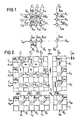
- first waveguide eW i and a second waveguide zW j are arranged with an optical coupler K ij which can be switched individually between two switching states.
- Each of these optical couplers K ij is designed in such a way that, in one of the two switching states, it couples a power component of an optical wave guided in one of the two waveguides eW i and zW j crossing at this crossing point into the other of these two waveguides eW i and zW j , it being essential that the degree of decoupling of this coupler K ij , ie the ratio between that decoupled from this coupler K ij
- the proportion of power to the power of the optical wave fed to this coupler K ij is deliberately low, and that the coupler K ij in the other switching state has an even smaller degree of decoupling than the low degree of decoupling.
- a low degree of decoupling means that this degree of decoupling is at least of the same order of magnitude or preferably less than the reciprocal 1 / M or 1 / N of the number M or N of the first or second waveguides eW i or zW j .
- the even smaller degree of decoupling should be as small as possible, ideally zero. It is also favorable if the transmission loss of the waveguides and couplers is as small as possible, ideally zero.
- the deliberately low degree of decoupling advantageously has the result that the first and second waveguides eW i and zW j can cross at a very large angle, in particular at an angle of 90 °, and that the couplers K ij are designed with an extremely short coupling or installation length can be made, which in turn enables matrices with an extremely large number of couplers and extremely small dimensions.
- the couplers with Mach-Zehnder structure or directional coupler structure are less good or not suitable.
- the actual coupling zone could be selected to be negligibly short in order to achieve the desired low degree of decoupling, but this would not significantly reduce the overall length of the coupler because the angle between the input waveguides leading to the coupling zone and the output waveguides continuing from this zone Avoidance of losses caused by waveguide curvatures is only about 1 °.
- couplers with cross-over or x structure are suitable for implementing couplers K ij with a low degree of decoupling and an extremely short overall length.
- Each coupler K ij of the matrix according to FIG. 1 allows, for example, an optical wave guided from left to right in the first waveguide eW i in question, but in the one switching state couples a low power component of this optical wave corresponding to the low degree of decoupling into the relevant second waveguide zW j in which this share of performance is continued, for example downwards.
- all couplers K ij in particular couple out in the same direction.
- each coupler has the vertical arrows pointing downward, an optical wave coming up from the right, an optical wave coming from below to the left and one from above coming optical wave partially coupled out to the right.
- the concentrator function is obtained because the power components decoupled by the couplers K ij into a second waveguide zW j of optical waves guided in the first waveguides eW i are fed to a single output A ' j of the matrix on this second waveguide zW j . In addition, these power components add up.
- this attenuation is at least approximately -30 dB when using electro-optical materials and at least approximately -20 dB when using organic materials for the couplers K ij .
- the transmission loss in a conventional matrix with M inputs and N outputs using conventional electro-optical couplers increases linearly with the number of crossing points of the matrix, ie the transmission loss in such matrices is approximately (M + N) dB.
- the crosstalk per crossing point of the matrix is less than -80 dB.
- crosstalk in conventional electro-optical switches cannot be significant due to the small angle of about 1 ° between the feeding and the continuing optical waveguides depending on the ratio between the transverse diameter and the width of the waveguide and the wavelength of -20 dB to -30 dB fall below.
- the first and second waveguides eW i and zW j consist of strip-like waveguides integrated on a common substrate made of electro-optical material, for example L i NbO3, which are in a common Are arranged plane and intersect at least substantially vertically at the crossing points.
- optical coupler K ij each consist of an electro-optically producible Bragg grating, the grating lines GL of which run at least substantially at an angle of 45 ° to the respective longitudinal direction R 1 and R 2 of the first and second waveguides eW i and zW j which are in the same direction R for all couplers K ij .
- the linear dimension of a 1000x1000 matrix is then less than 10 mm.
- the coupling length L of the optical couplers with the low degree of coupling-out is very short, for example 10 ⁇ m.
- a linear expansion of the matrix becomes extremely small at a distance between the crossing points of the order of magnitude of 10 ⁇ m, even with a large number of crossing points. It is about 10.N ⁇ m, in conventional matrices, however, at least 8.N mm.
- the connection network of the neurons plays a decisive role in such neural networks. The strength of this connection represents the information stored.
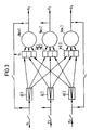
- Figure 3 the essential functional blocks of an exemplary and optically realizable neural network for three neurons Neu1, Neu2 and Neu3 are shown schematically.
- Input signals e1 to e3 are each divided in terms of performance in assigned signal splitting devices AE1 to AE3, the divided signals of different splitting devices AE1 to AE3 are multiplied in matrix multiplication devices ME1 to ME3 by matrix elements g ij and then added or integrated in a neuron Neu1, Neu2 and Neu3 and changed in accordance with the transfer function of the neuron.
- the system has formed an associated output pattern consisting of the input signals e 1, e 2, e 3 and an output pattern consisting of output signals a 1, a 2 and a 3.
- a device that performs such a matrix-vector multiplication with the required summation is referred to as a synapse matrix.
- the physical implementation of such a synapse matrix is of central importance for neural networks.
- the synapse matrix should also work optically, ie that the input signals e 1 to e M and output signals a 1 to a N forming a vector or a pattern are present optically and the input signals in the matrix are processed optically.
- the matrix according to the invention according to FIG. 1 or 2 can advantageously be used as an optically operating synapse matrix, since in this matrix the power components decoupled by the couplers K ij into the second waveguide zW j add up to form a sum signal. Because of the reciprocity of the optical couplers K ij , this sum signal is weakened in the relevant intersection points, but only slightly according to the number of these intersection points.
- a matrix according to the invention with M inputs and N outputs also realizes a complete neural network of the structure according to FIG. 3 with N neurons for M input signals e 1 to e M , because, due to the broadcasting function implemented on the first waveguides eW i , advantageously the signal splitting devices at the same time AEi are inherently realized.
- the degree of decoupling of each coupler K ij should be of the order of 1 / (10th N), which corresponds to a decoupling of -30 dB or an insertion loss of +30 dB for 100 outputs or neurons.
- the problem of control of the coupler K ij can be solved so that the control information of each coupler K ij assigned as the charge amount on a this coupler K ij capacitor C ij, is stored for example in the FET embodiment, which is practically unloaded via a high-impedance output and optionally feeds the electrodes of the coupler K ij .
- the matrices in distribution networks are also subject to demands for low insertion losses, low crosstalk and short overall lengths.
- Signals from any of the M inputs E i are to be switched through to any of the N outputs A j . It may be desirable that an input signal e i is switched to only one output A j or to several outputs simultaneously.
- the degree of decoupling is again selected 1 / (10.N).
- the insertion loss in the matrix according to the invention is approximately (10 + 10 log N) dB.
- the loss between input and output increases linearly with the number of crosspoints, so it is (M + N) dB.
- amplifiers with a non-linear characteristic curve could be provided on the first waveguides eW i which have the broadcasting function and raise the power levels to a constant value along these first waveguides eW i .
- Amplifiers for raising the signal level can be provided at the outputs A j of the matrix.
- the exemplary matrix according to FIG. 4 differs from the exemplary matrix according to FIG. 2 only in the couplers K ij , which in the matrix according to FIG. 4 are non-switchable couplers with a fixed degree of decoupling.
- the first and second optical waveguides eW i and zW j each have, for example, a triangular region Be with a refractive index n 1 that is higher than the refractive index n0 of the waveguides eW i and zW j outside of these regions Be.
- each area Be defines a non-switchable coupler K ij with a fixed degree of decoupling.
- the desired degree of coupling-out can be determined by controlling ⁇ n and / or the penetration depth of the ions.
- the matrix according to FIG. 4 can be used, for example, as an optical mixer or star coupler, the coupling levels of the non-switchable couplers being chosen so low that each of the input signals e 1 to e M to be mixed is only slight on the horizontal path of the first waveguide eW i assigned to it , for example 10% is weakened.
- This low degree of decoupling also fulfills the second requirement that the light components which are coupled out into a vertical second waveguide zW j and added up to the output A ' j assigned to this waveguide are only slightly weakened, for example at worst by 10%, this being the case for every second Waveguide zW j and the output A ' j assigned to it apply.
- the input signals to be mixed e1 to e M are, for example, given in parallel to the inputs E1 to E n , while the mixed output signals a1 to a N the outputs A'1 to A ' N can be removed.
Landscapes
- Physics & Mathematics (AREA)
- General Physics & Mathematics (AREA)
- Optics & Photonics (AREA)
- Optical Integrated Circuits (AREA)
Applications Claiming Priority (2)
| Application Number | Priority Date | Filing Date | Title |
|---|---|---|---|
| DE4007976 | 1990-03-13 | ||
| DE4007976 | 1990-03-13 |
Publications (2)
| Publication Number | Publication Date |
|---|---|
| EP0446437A2 true EP0446437A2 (fr) | 1991-09-18 |
| EP0446437A3 EP0446437A3 (en) | 1992-10-28 |
Family
ID=6402096
Family Applications (1)
| Application Number | Title | Priority Date | Filing Date |
|---|---|---|---|
| EP19900123235 Ceased EP0446437A3 (en) | 1990-03-13 | 1990-12-04 | Optical matrix |
Country Status (1)
| Country | Link |
|---|---|
| EP (1) | EP0446437A3 (fr) |
Cited By (3)
| Publication number | Priority date | Publication date | Assignee | Title |
|---|---|---|---|---|
| EP0615390A3 (en) * | 1993-03-09 | 1995-10-25 | Hitachi Ltd | Optical switch, optical matrix switch system and method of optimizing system connectivity. |
| DE19702743A1 (de) * | 1997-01-15 | 1998-07-23 | Siemens Ag | Integriert-optische Schaltanordnung |
| EP0876069A1 (fr) * | 1997-05-02 | 1998-11-04 | Alcatel | Réseau de commutateurs |
Family Cites Families (1)
| Publication number | Priority date | Publication date | Assignee | Title |
|---|---|---|---|---|
| FR2429445A1 (fr) * | 1978-06-20 | 1980-01-18 | Favre Francois | Circuit electro-optique integre destine a la commutation de signaux achemines par voie optique |
-
1990
- 1990-12-04 EP EP19900123235 patent/EP0446437A3/de not_active Ceased
Cited By (5)
| Publication number | Priority date | Publication date | Assignee | Title |
|---|---|---|---|---|
| EP0615390A3 (en) * | 1993-03-09 | 1995-10-25 | Hitachi Ltd | Optical switch, optical matrix switch system and method of optimizing system connectivity. |
| US5790290A (en) * | 1993-03-09 | 1998-08-04 | Hitachi, Ltd. | Optical distribution system having time switch |
| DE19702743A1 (de) * | 1997-01-15 | 1998-07-23 | Siemens Ag | Integriert-optische Schaltanordnung |
| EP0876069A1 (fr) * | 1997-05-02 | 1998-11-04 | Alcatel | Réseau de commutateurs |
| FR2762948A1 (fr) * | 1997-05-02 | 1998-11-06 | Alsthom Cge Alcatel | Reseau de commutateurs |
Also Published As
| Publication number | Publication date |
|---|---|
| EP0446437A3 (en) | 1992-10-28 |
Similar Documents
| Publication | Publication Date | Title |
|---|---|---|
| DE69523104T2 (de) | Phasengekoppelte optische vorrichtung | |
| DE3209927C2 (fr) | ||
| DE69120479T2 (de) | Durch elektrisches feld induzierter quanten-potentialtopf-wellenleiter | |
| EP0662621B1 (fr) | Dispositif optique comprenant de guides d'onde optiques en ruban | |
| EP0782809B1 (fr) | Matrice de commutation optique 1xn et nxn arborescente | |
| DE1639269C3 (de) | Vorrichtung zur steuerbaren Ablenkung eines mehrere Weilenlängen enthaltenden Lichtstrahls | |
| DE60010053T2 (de) | Elektrisch verstellbares beugungsgitter | |
| DE69013130T2 (de) | Optischer räumlicher Schalter und Netzwerk mit derartigen optischen räumlichen Schaltern. | |
| DE4326196A1 (de) | Planarer elektro-optischer Lichtstrahlablenker und Verfahren zu seiner Herstellung | |
| DE3883492T2 (de) | Verfahren zur Anordnung eines polarisationsrichtenden optoelektronischen Schalters und ein Schalter dafür. | |
| DE2804105A1 (de) | Elektrisch steuerbare optische uebertragungsvorrichtung | |
| EP1070271B1 (fr) | Configuration destinee a la separation et/ou la reunion spatiale de canaux de longueurs d'ondes optiques | |
| DD150816A5 (de) | Steuerschaltung zur erzeugung mehrerer ausgangslaserstrahlen | |
| DE2526117C2 (de) | Integrierter elektrooptischer Schalter | |
| EP0260595A2 (fr) | Dispositif de contrôle de polarisation et de phase continu et sans remise à zéro | |
| DE69418798T2 (de) | Aktives optisches Halbleiter-Stegwellenleiterelement | |
| DE69216299T2 (de) | Richtkoppleroptische Vorrichtung und Steuerverfahren dafür | |
| EP0704946A1 (fr) | Composant opto-électronique multi-longueurs d'onde | |
| DE3881138T2 (de) | Optisches schaltelement aus zwei parallelen lichtleitern und aus solchen elementen zusammengesetzte schaltmatrix. | |
| DE69105614T2 (de) | Digitaler optischer Schalter. | |
| EP0446437A2 (fr) | Matrice optique | |
| DE2619327A1 (de) | Elektrooptischer umschalter | |
| DE60127667T2 (de) | Optischer flüssigkristallschalter mit zuverlässiger steuerung | |
| DE69624915T2 (de) | Ein laserverstärker,ein einen solchen laserverstärker enthaltendes optisches system und ein verfahren zur herstellung eines solchen laserverstärkers | |
| DE2033965B2 (de) | Digitale lichtablenkvorrichtung |
Legal Events
| Date | Code | Title | Description |
|---|---|---|---|
| PUAI | Public reference made under article 153(3) epc to a published international application that has entered the european phase |
Free format text: ORIGINAL CODE: 0009012 |
|
| 17P | Request for examination filed |
Effective date: 19901220 |
|
| AK | Designated contracting states |
Kind code of ref document: A2 Designated state(s): AT BE CH DE FR GB IT LI NL SE |
|
| PUAL | Search report despatched |
Free format text: ORIGINAL CODE: 0009013 |
|
| AK | Designated contracting states |
Kind code of ref document: A3 Designated state(s): AT BE CH DE FR GB IT LI NL SE |
|
| 17Q | First examination report despatched |
Effective date: 19951102 |
|
| STAA | Information on the status of an ep patent application or granted ep patent |
Free format text: STATUS: THE APPLICATION HAS BEEN REFUSED |
|
| 18R | Application refused |
Effective date: 20011029 |