EP0446461A2 - Lampe à incandescence à halogène munie d'un pincement unique - Google Patents
Lampe à incandescence à halogène munie d'un pincement unique Download PDFInfo
- Publication number
- EP0446461A2 EP0446461A2 EP90124461A EP90124461A EP0446461A2 EP 0446461 A2 EP0446461 A2 EP 0446461A2 EP 90124461 A EP90124461 A EP 90124461A EP 90124461 A EP90124461 A EP 90124461A EP 0446461 A2 EP0446461 A2 EP 0446461A2
- Authority
- EP
- European Patent Office
- Prior art keywords
- bulb
- halogen incandescent
- incandescent lamp
- luminous element
- web
- Prior art date
- Legal status (The legal status is an assumption and is not a legal conclusion. Google has not performed a legal analysis and makes no representation as to the accuracy of the status listed.)
- Granted
Links
- 229910052736 halogen Inorganic materials 0.000 title claims description 22
- 150000002367 halogens Chemical class 0.000 title claims description 22
- 239000011521 glass Substances 0.000 claims abstract description 22
- 239000000463 material Substances 0.000 claims abstract description 6
- 241000283216 Phocidae Species 0.000 description 8
- VYPSYNLAJGMNEJ-UHFFFAOYSA-N Silicium dioxide Chemical compound O=[Si]=O VYPSYNLAJGMNEJ-UHFFFAOYSA-N 0.000 description 3
- ZOKXTWBITQBERF-UHFFFAOYSA-N Molybdenum Chemical compound [Mo] ZOKXTWBITQBERF-UHFFFAOYSA-N 0.000 description 2
- 238000010891 electric arc Methods 0.000 description 2
- 230000002349 favourable effect Effects 0.000 description 2
- 239000011888 foil Substances 0.000 description 2
- 238000000034 method Methods 0.000 description 2
- 229910052750 molybdenum Inorganic materials 0.000 description 2
- 239000011733 molybdenum Substances 0.000 description 2
- 241001188564 Gymnosoma par Species 0.000 description 1
- 238000005452 bending Methods 0.000 description 1
- 239000000919 ceramic Substances 0.000 description 1
- 238000010276 construction Methods 0.000 description 1
- 238000004031 devitrification Methods 0.000 description 1
- 238000005516 engineering process Methods 0.000 description 1
- 238000005429 filling process Methods 0.000 description 1
- 150000002366 halogen compounds Chemical class 0.000 description 1
- 230000017525 heat dissipation Effects 0.000 description 1
- 239000011261 inert gas Substances 0.000 description 1
- 238000004519 manufacturing process Methods 0.000 description 1
- 230000035945 sensitivity Effects 0.000 description 1
- 230000035939 shock Effects 0.000 description 1
- 238000003892 spreading Methods 0.000 description 1
- 239000005341 toughened glass Substances 0.000 description 1
- 230000007704 transition Effects 0.000 description 1
- WFKWXMTUELFFGS-UHFFFAOYSA-N tungsten Chemical compound [W] WFKWXMTUELFFGS-UHFFFAOYSA-N 0.000 description 1
Images


Classifications
-
- H—ELECTRICITY
- H01—ELECTRIC ELEMENTS
- H01K—ELECTRIC INCANDESCENT LAMPS
- H01K1/00—Details
- H01K1/18—Mountings or supports for the incandescent body
Definitions
- the invention relates to a halogen incandescent lamp pinched on one side according to the preamble of claim 1.
- Such a halogen incandescent lamp is known from DE-GM 87 16 797.
- the axial filament is held by a frame that is formed by the two power supplies.
- a support wire is also provided, which is attached approximately in the middle of the filament.
- the structure of the frame is greatly simplified by the arrangement according to the invention.
- the support wire is replaced by a glass web, which is formed from the material of the bulb and into which a section of the filament is squeezed.
- the crossbar can be saved and thus the overall height of the lamp can be reduced.
- the good fixation of the filament also improves the shock resistance of the lamp. This also considerably reduces the spiral sag, which can lead to contact with the inner wall of the piston.
- the invention is preferably suitable for halogen incandescent lamps which are directly connected to the mains voltage.
- the conditions are particularly favorable for mains voltages of approx. 110 - 120 V or less, since then the length and rigidity of the filament reach the most favorable values.
- a single glass web is then sufficient, which fixes the luminous element approximately in the middle.
- mains voltages e.g. 230 V
- the luminous element is advantageously subdivided into luminous sections which are double-helixed and connecting sections which are single-helixed. Under certain circumstances, simply coiled filament sections and uncoiled sections as connecting sections can also be used as luminous sections.
- the connecting sections advantageously have a reduced power density compared to the luminous sections.
- connection section can advantageously have a core pin in the region of the glass web.
- the webs are only produced after being squeezed, but before filling.
- the lamp bulb is heated in the area of the future webs with burners and shaped by means of stamps, which are opposite each other.
- This technology has the great advantage that the position of the luminous element can no longer be subsequently adjusted by this process, even in the case of frames without a crossbar.
- the webs can be produced particularly easily by deep-drawing two "glass fingers” using two rod-shaped stamps, a stopper being left in the lamp axis when the two "glass fingers” touch.
- halogen incandescent lamp with a long service life (2000 hours) for general lighting is presented, which is extremely shockproof and suitable for a simple construction with few components (without crossbars).
- the pipe diameter can be reduced by approx. 2-4 mm and the overall length by approx. 7 mm, so that additional savings in filling quantities occur due to the smaller piston volume.
- this lamp Due to the small size of this lamp, it is ideal for use in an outer bulb. Possibly. it can be equipped with a reflector which has, for example, a parabolic contour (so-called halogen PAR lamp).
- the lamp according to the invention is suitable for direct operation at mains voltage, which should be understood to mean a range from approximately 80 V to 250 V. Typical wattages are 15 to 500 W.
- mains voltage which should be understood to mean a range from approximately 80 V to 250 V. Typical wattages are 15 to 500 W.
- the lamp can be surrounded with an outer bulb. Due to its compactness, this lamp can also be used advantageously in reflectors (e.g. PAR lamps, cold light reflector lamps) and optionally equipped with screw or pin bases.
- Quartz glass is preferred as the piston material, since this material can best withstand the high temperatures and the stresses occurring on the glass web. Tempered glass can also be used for lamps with low power consumption.
- the mounting of the filament can be further improved in that the current supply leading to the distal end of the filament in a plane, which includes the filament, has a hairpin-shaped section that runs along the lamp axis is arranged. Each leg of this section opens into a slope facing the piston wall.
- the curved section is suitable as a holder for a - preferably double - coiled end section of the filament. While in previous holders of this type only one arm of the power supply could be used to hold the luminous element, so that only half-hearted measures such as a simple bending of the frame arm or a flattening could be considered for a non-slip fit (cf. e.g. again DE-GM 87 16 797 or also US Pat. No.
- a further simplification of the frame structure can be achieved in that the power supply, which connects the near-pinch end of the filament with the associated film, is formed by a simply coiled end section of the filament.
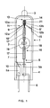
- Figures 1 and 2 show schematically different side views of a 120 V halogen incandescent lamp 1 with a power of 90 W. It has a cylindrical bulb 2 made of quartz glass with a total length of 40 mm, which at one end, which is rounded, with a pump tip 3 one or more halogen compounds and was filled with inert gas. The other end of the piston 2 is provided with a pinch seal 4, to which, for example, a ceramic base (not shown) can be attached. Two molybdenum foils 5a, 5b are melted asymmetrically into the pinch seal 4 and connect the two outer power supply lines 6 with two inner power supply lines 7, 8 in an electrically conductive and vacuum-tight manner.
- the first inner power supply 7 (made of tungsten wire) is guided along the inner wall 9 of the piston to the end of the piston which is distant from the pinch. Its pinch-side end 10 is from the inner wall 9 to the film 5a, which is arranged on the edge of the pinch seal, bent away, while its pinch-distant end 11 forms a first bevel 12a, which is bent against the inner wall 9 by about 60 ° to the lamp axis. Shortly before reaching the lamp axis, one leg 13a of a hairpin-shaped section 13 aligned parallel to the lamp axis is attached to it. The bend 14 of the section 13 is directed towards the pump tip 3; however, it is clearly spaced from it.
- the free end of the power supply is designed as a second leg 13b and second bevel 12b in mirror image of the first leg 13a and the first slope 12a.
- the second slope 12b ends at the opposite piston inner wall 9 'and is bent into a short extension 15 which points along the piston inner wall 9' in the direction of the pinch seal 4.
- the inner power supply 7 is resiliently clamped between two diametrically opposite points on the inner wall of the bulb and automatically centers a luminous element 16 in the lamp axis.
- the luminous element 16 is equipped with two double-coiled luminous sections 17 and is stretched axially in the bulb between the second film 5b and the hairpin-shaped section 13.
- the two double coiled sections 17 are spaced apart from one another by a single coiled connecting section 18.
- An also simply coiled end section of the filament takes over the function of the second inner power supply 8 and extends in a straight line from the lit section 17 near the pinch to the second film 5b, which is symmetrical is arranged to the lamp axis in the middle of the pinch seal.
- the luminous element 16 is fixed in the middle of the connecting section 18 by a glass web 19 which extends transversely to the lamp axis and to the plane which contains the luminous element 16 and the first power supply 7.
- the glass web 19 is designed as a tube which extends approximately in the middle of the bulb over the inner diameter of the bulb.
- the tube has an inner diameter of approx. 1-2 mm near the axis and widens towards the piston wall on both sides in the manner of a funnel to about twice to four times the diameter.
- the tube has a circular cross section.
- an elongated or oval cross section near the axis is particularly advantageous (as shown in FIGS. 1 and 2), since this facilitates the fixation of the luminous element.
- the longer axis of the tube is aligned transversely to the lamp axis and to the filament.
- the ratio between the longer axis and the shorter axis of the tube is approximately 2: 1.
- the filament is squeezed into the glass web 19 so that a type of plug 20 is left in the tube near the axis.
- the glass web 19 takes over the function of a frame part.
- Another frame part is formed by the first inner power supply 7, which holds the end of the luminous element that is distant from the pinch.
- the non-crushing, double-coiled luminous section 17 of the luminous element is connected to a double-coiled, short end section 21 via a short connecting section 18 '.
- This end section 21 is drawn onto the hairpin-shaped section 13 of the power supply.
- the two spread legs 12 secure the end portion 21 against slipping out.
- the same features are provided with the same reference numbers.
- the luminous element 16 which is longer due to the higher voltage, has three luminous sections 22 which are spaced apart by two connecting sections 23. Each connecting section 23 is fixed by a glass web 24.
- the halogen incandescent lamp 1 is mounted in an outer bulb 25 with a screw base, which has a parabolic reflector 26 (halogen PAR lamps).
- the two outer power supply lines 6 are squeezed in a plate base 27 and connected to the screw base 28 in a manner known per se.
- the plate foot 27 is melted into the neck 29 of the evacuated outer bulb 25.
- the invention is not restricted to the exemplary embodiments shown.
- the two Molybdenum foils one of which is arranged laterally on the edge of the pinch seal and one in the middle, have different widths, or the centrally arranged film can be melted transversely into the pinch seal.
- This also simplifies the frame structure, since there is no need to bend the shorter of the two power leads out of the lamp axis.
- this is in turn the prerequisite for the fact that the simply coiled end section of the filament can be used as the power supply.
- the cylindrical glass bulb has a circular cross section.
- an elongated cross section e.g. elliptical
- the glass webs extending in the direction of the shorter axis to ensure a certain minimum thickness of the glass webs.
Landscapes
- Non-Portable Lighting Devices Or Systems Thereof (AREA)
- Vessels And Coating Films For Discharge Lamps (AREA)
Applications Claiming Priority (4)
| Application Number | Priority Date | Filing Date | Title |
|---|---|---|---|
| DE19904008334 DE4008334A1 (de) | 1990-03-15 | 1990-03-15 | Einseitig gequetschte halogengluehlampe |
| DE4008334 | 1990-03-15 | ||
| DE9013457U | 1990-09-24 | ||
| DE9013457U DE9013457U1 (de) | 1990-09-24 | 1990-09-24 | Einseitig gequetschte Halogen-Glühlampe |
Publications (3)
| Publication Number | Publication Date |
|---|---|
| EP0446461A2 true EP0446461A2 (fr) | 1991-09-18 |
| EP0446461A3 EP0446461A3 (en) | 1992-02-26 |
| EP0446461B1 EP0446461B1 (fr) | 1995-07-12 |
Family
ID=25891174
Family Applications (1)
| Application Number | Title | Priority Date | Filing Date |
|---|---|---|---|
| EP90124461A Expired - Lifetime EP0446461B1 (fr) | 1990-03-15 | 1990-12-17 | Lampe à incandescence à halogène munie d'un pincement unique |
Country Status (3)
| Country | Link |
|---|---|
| EP (1) | EP0446461B1 (fr) |
| JP (1) | JP2501993Y2 (fr) |
| DE (1) | DE59009403D1 (fr) |
Cited By (4)
| Publication number | Priority date | Publication date | Assignee | Title |
|---|---|---|---|---|
| GB2324907A (en) * | 1997-04-18 | 1998-11-04 | Koito Mfg Co Ltd | Wedge-based bulb with ribs or grooves for allowing easy coating of bulb |
| EP1441384A2 (fr) | 2003-01-24 | 2004-07-28 | Patent-Treuhand-Gesellschaft für elektrische Glühlampen mbH | Réflecteur et lampe à réflecteur |
| EP1667204A3 (fr) * | 2004-12-06 | 2007-06-27 | Patent-Treuhand-Gesellschaft für elektrische Glühlampen mbH | Système d'alimentation de courant pour une lampe et une lampe avec ce système d'alimentation |
| DE102015208574A1 (de) | 2015-05-08 | 2016-11-10 | Osram Gmbh | Lampe |
Family Cites Families (2)
| Publication number | Priority date | Publication date | Assignee | Title |
|---|---|---|---|---|
| GB1147140A (en) * | 1967-03-10 | 1969-04-02 | Sylvania Electric Prod | Incandescent lamp |
| DE8325715U1 (de) * | 1983-09-07 | 1985-02-21 | Radium-Elektrizitäts-Gesellschaft mbH, 5272 Wipperfürth | Zweiseitig gesockelte gluehlampe |
-
1990
- 1990-12-17 EP EP90124461A patent/EP0446461B1/fr not_active Expired - Lifetime
- 1990-12-17 DE DE59009403T patent/DE59009403D1/de not_active Expired - Fee Related
-
1991
- 1991-03-13 JP JP1991014386U patent/JP2501993Y2/ja not_active Expired - Lifetime
Cited By (7)
| Publication number | Priority date | Publication date | Assignee | Title |
|---|---|---|---|---|
| GB2324907A (en) * | 1997-04-18 | 1998-11-04 | Koito Mfg Co Ltd | Wedge-based bulb with ribs or grooves for allowing easy coating of bulb |
| GB2324907B (en) * | 1997-04-18 | 1999-04-28 | Koito Mfg Co Ltd | Wedge-base bulb and method for coating glass bulb of wedge-base bulb |
| US6411021B1 (en) | 1997-04-18 | 2002-06-25 | Koito Manufacturing Co., Ltd | Wedge base bulb with color coating |
| EP1441384A2 (fr) | 2003-01-24 | 2004-07-28 | Patent-Treuhand-Gesellschaft für elektrische Glühlampen mbH | Réflecteur et lampe à réflecteur |
| EP1667204A3 (fr) * | 2004-12-06 | 2007-06-27 | Patent-Treuhand-Gesellschaft für elektrische Glühlampen mbH | Système d'alimentation de courant pour une lampe et une lampe avec ce système d'alimentation |
| US7304421B2 (en) | 2004-12-06 | 2007-12-04 | Patent-Treuhand-Gesellschaft für elecktrische Glühampen mbH | Power supply system for a lamp and lamp having this power supply system |
| DE102015208574A1 (de) | 2015-05-08 | 2016-11-10 | Osram Gmbh | Lampe |
Also Published As
| Publication number | Publication date |
|---|---|
| JPH0499354U (fr) | 1992-08-27 |
| EP0446461A3 (en) | 1992-02-26 |
| DE59009403D1 (de) | 1995-08-17 |
| EP0446461B1 (fr) | 1995-07-12 |
| JP2501993Y2 (ja) | 1996-06-19 |
| HK1000612A1 (en) | 1998-04-09 |
Similar Documents
| Publication | Publication Date | Title |
|---|---|---|
| EP0446460B1 (fr) | Lampe à incandescence à halogène munie d'un pincement unique | |
| EP0239006B1 (fr) | Lampe à incandescence à halogène et son procédé de fabrication | |
| EP0453652B1 (fr) | Lampe à décharge à haute pression | |
| DE2821459A1 (de) | Wolfram-halogen-gluehlampe hoher wattleistung | |
| DE1988671U (de) | Elektrische gluehlampe. | |
| DE6804136U (de) | Halogen-quarz-lampe | |
| EP0446461B1 (fr) | Lampe à incandescence à halogène munie d'un pincement unique | |
| EP0446458B1 (fr) | Lampe à incandescence à halogène à double pincement | |
| EP1355344A2 (fr) | Lampe électrique | |
| EP0061757B1 (fr) | Méthode pour sceller par pincement une lampe éléctrique et dispositif de pincement pour la mise en oeuvre de cette méthode | |
| WO2010060699A1 (fr) | Lampe à incandescence à halogène pour le fonctionnement sur la tension du réseau | |
| DE8716797U1 (de) | Halogenglühlampe | |
| DE9013457U1 (de) | Einseitig gequetschte Halogen-Glühlampe | |
| EP0446459B1 (fr) | Lampe à incandescence à halogène munie d'un pincement unique | |
| DE4008334A1 (de) | Einseitig gequetschte halogengluehlampe | |
| DE1702093U (de) | Roehrenfoermige entladungslampe. | |
| DE102010003630A1 (de) | Halogenglühlampe | |
| DE9102566U1 (de) | Halogenglühlampe | |
| DE9115714U1 (de) | Einseitig verschlossene elektrische Glühlampe | |
| WO2005029529A2 (fr) | Lampe electrique scellee des deux cotes et procede de fabrication | |
| DE1539527C (de) | Quecksilberhochdrucklampe kleiner Leistung und kleiner Abmessung | |
| AT398864B (de) | Halogenglühlampe | |
| DE8812009U1 (de) | Einseitig gequetschte Halogenglühlampe | |
| DE4106851A1 (de) | Einseitig gequetschte halogengluehlampe | |
| DE8812010U1 (de) | Einseitig gequetschte Halogenglühlampe |
Legal Events
| Date | Code | Title | Description |
|---|---|---|---|
| PUAI | Public reference made under article 153(3) epc to a published international application that has entered the european phase |
Free format text: ORIGINAL CODE: 0009012 |
|
| 17P | Request for examination filed |
Effective date: 19901217 |
|
| AK | Designated contracting states |
Kind code of ref document: A2 Designated state(s): DE FR GB IT |
|
| PUAL | Search report despatched |
Free format text: ORIGINAL CODE: 0009013 |
|
| AK | Designated contracting states |
Kind code of ref document: A3 Designated state(s): DE FR GB IT |
|
| 17Q | First examination report despatched |
Effective date: 19940914 |
|
| GRAA | (expected) grant |
Free format text: ORIGINAL CODE: 0009210 |
|
| AK | Designated contracting states |
Kind code of ref document: B1 Designated state(s): DE FR GB IT |
|
| REF | Corresponds to: |
Ref document number: 59009403 Country of ref document: DE Date of ref document: 19950817 |
|
| ITF | It: translation for a ep patent filed | ||
| GBT | Gb: translation of ep patent filed (gb section 77(6)(a)/1977) |
Effective date: 19950915 |
|
| ET | Fr: translation filed | ||
| PLBE | No opposition filed within time limit |
Free format text: ORIGINAL CODE: 0009261 |
|
| STAA | Information on the status of an ep patent application or granted ep patent |
Free format text: STATUS: NO OPPOSITION FILED WITHIN TIME LIMIT |
|
| 26N | No opposition filed | ||
| REG | Reference to a national code |
Ref country code: GB Ref legal event code: IF02 |
|
| PGFP | Annual fee paid to national office [announced via postgrant information from national office to epo] |
Ref country code: GB Payment date: 20041207 Year of fee payment: 15 |
|
| PGFP | Annual fee paid to national office [announced via postgrant information from national office to epo] |
Ref country code: FR Payment date: 20041223 Year of fee payment: 15 |
|
| PG25 | Lapsed in a contracting state [announced via postgrant information from national office to epo] |
Ref country code: IT Free format text: LAPSE BECAUSE OF NON-PAYMENT OF DUE FEES;WARNING: LAPSES OF ITALIAN PATENTS WITH EFFECTIVE DATE BEFORE 2007 MAY HAVE OCCURRED AT ANY TIME BEFORE 2007. THE CORRECT EFFECTIVE DATE MAY BE DIFFERENT FROM THE ONE RECORDED. Effective date: 20051217 Ref country code: GB Free format text: LAPSE BECAUSE OF NON-PAYMENT OF DUE FEES Effective date: 20051217 |
|
| GBPC | Gb: european patent ceased through non-payment of renewal fee |
Effective date: 20051217 |
|
| PG25 | Lapsed in a contracting state [announced via postgrant information from national office to epo] |
Ref country code: FR Free format text: LAPSE BECAUSE OF NON-PAYMENT OF DUE FEES Effective date: 20060831 |
|
| REG | Reference to a national code |
Ref country code: FR Ref legal event code: ST Effective date: 20060831 |
|
| PGFP | Annual fee paid to national office [announced via postgrant information from national office to epo] |
Ref country code: DE Payment date: 20080218 Year of fee payment: 18 |
|
| PG25 | Lapsed in a contracting state [announced via postgrant information from national office to epo] |
Ref country code: DE Free format text: LAPSE BECAUSE OF NON-PAYMENT OF DUE FEES Effective date: 20090701 |